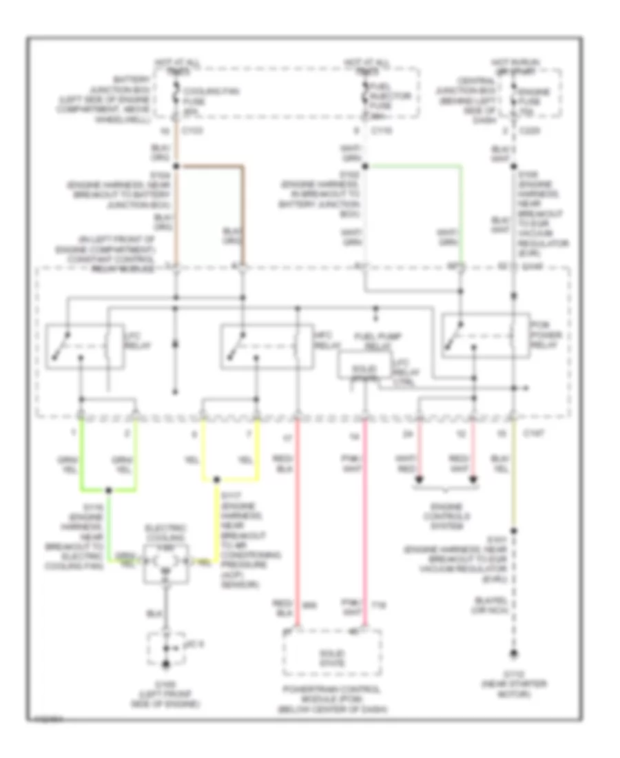
COOLING FAN
Cooling Fan Wiring Diagram for Mercury Tracer GS 1999
 https://portal-diagnostov.com/license.html
Automotive Electricians Portal FZCO
Automotive Electricians Portal FZCO
https://portal-diagnostov.com/license.html
https://portal-diagnostov.com/license.html
Automotive Electricians Portal FZCO
Automotive Electricians Portal FZCO
List of elements for Cooling Fan Wiring Diagram for Mercury Tracer GS 1999:
- (in left front of engine compartment) constant control relay module
- Battery junction box (left side of engine compartment, above wheelwell)
- C110
- C133
- C147
- C220
- Central junction box (behind left side of dash
- Cooling fan fuse 40a
- Electric cooling fan
- Engine controls system
- Engine fuse 15a
- Fuel injector fuse 30a
- Fuel pump relay
- G100 (left front side of engine)
- G112 (near starter motor)
- Hfc relay
- Hot at all times
- Hot in run or start
- J/c 6
- Lfc relay
- Lfc relay ctrl
- Pcm power relay
- Powertrain control module (pcm) (below center of dash)
- S101 (engine harness, near breakout to egr vacuum regulator (evr))
- S102 (engine harness, in breakout to battery junction box)
- S104 (engine harness, near breakout to battery junction box)
- S116 (engine harness, near breakout to electric cooling fan)
- S117 (engine harness, near breakout to air conditioning pressure (acp) sensor)
- Solid state
 Čeština
 Dansk
Dansk Deutsch
 Ελληνικά
 English
 English
 Español
 Suomi
Suomi Français
 Français
 עברית
עברית Hrvatski
 Magyar
 Italiano
 日本語
日本語 한국어
한국어 Nederlands
 Polski
 Português
 Português
 Română
 Русский
 Slovenčina
 Slovenščina
 Svenska
 Türkçe
 中文 (中国)
