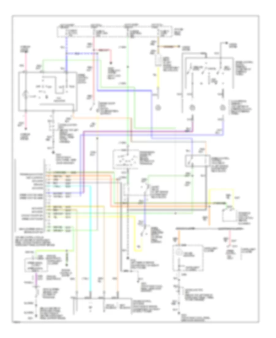
CRUISE CONTROL
Cruise Control Wiring Diagram for Mercury Villager GS 1995
 https://portal-diagnostov.com/license.html
Automotive Electricians Portal FZCO
Automotive Electricians Portal FZCO
https://portal-diagnostov.com/license.html
https://portal-diagnostov.com/license.html
Automotive Electricians Portal FZCO
Automotive Electricians Portal FZCO
List of elements for Cruise Control Wiring Diagram for Mercury Villager GS 1995:
- "cruise" indicator
- "on"
- "on" input
- (analog) (electronic)
- (behind top left side of instrument panel, taped to main harness)
- (below center of instrument panel, on right side of center instrument panel support brace)
- (in left engine compartment relay block)
- (right side of engine, compartment on front of strut tower)
- (shift lock relay)
- (top of right cowl panel, near
- Accel
- Actuator
- Analog cluster
- Brake on/off (boo) switch (on brake pedal support)
- Brake on/off sw
- C266
- C268 c272
- C274
- Cancel
- Clockspring assembly (top center of steering column, below steering wheel)
- Compartment relay block)
- Cr cont on/off sw
- Cruise control actuator
- Cruise control module (below center of instrument panel, on right side of center instrument panel support brace)
- Diode junction box
- Diode junction box (behind top left side of instrument panel, taped to main harness)
- Door grommet)
- Ej04
- Ej06
- Ej07
- Ej08
- Ej09
- Ej10
- Ej13
- Ej14
- Ej15
- Ej16
- Eje1
- Ejo1
- Ejo2
- Electronic cluster
- Engine compartment relay block)
- Engine controls system
- Fuse 18 horn 15a
- Fuse 20 rly coil 10a
- Fuse 24 stop lamp 15a
- Fuse 26 electron ign 10a
- G102 (left rear of engine compartment, on side of strut tower)
- G201
- G203
- G203 (top of right cowl panel, near door grommet)
- G203 (top of right cowl panel, near door grommet)
- Glove box)
- Ground
- Horn relay (in left
- Horns system
- Hot at all times
- Hot in start or run
- I/p fuse/ relay panel
- Illum
- Indicator
- Inhibit relay (in left engine
- Input
- Inst clstr/tcm
- Instrument cluster
- Interior lights system
- Nca
- Off
- Ohms
- Output
- Pnk
- Pnk/
- Red
- Red/
- Resume/
- Set/ coast
- Shift interlock system
- Speed control
- Speed cont dis sw
- Speed cont sw assm
- Speed control control hold relay
- Speed control disengage switch (on brake pedal support)
- Speed control on/off switch
- Speed control switch assembly (in center of steering wheel)
- Speed signal
- Transaxle cont mod
- Transaxle control module (tcm) (behind
- Transaxle)
- Transmission range (tr) switch sensor (on front of transaxle)
- Vacuum solenoid
- Vehicle speed sensor (vss) (on rear of
- Vehicle speed signal
- Vent solenoid
 Čeština
 Dansk
Dansk Deutsch
 Ελληνικά
 English
 English
 Español
 Suomi
Suomi Français
 Français
 עברית
עברית Hrvatski
 Magyar
 Italiano
 日本語
日本語 한국어
한국어 Nederlands
 Polski
 Português
 Português
 Română
 Русский
 Slovenčina
 Slovenščina
 Svenska
 Türkçe
 中文 (中国)
