ENGINE PERFORMANCE
4.2L
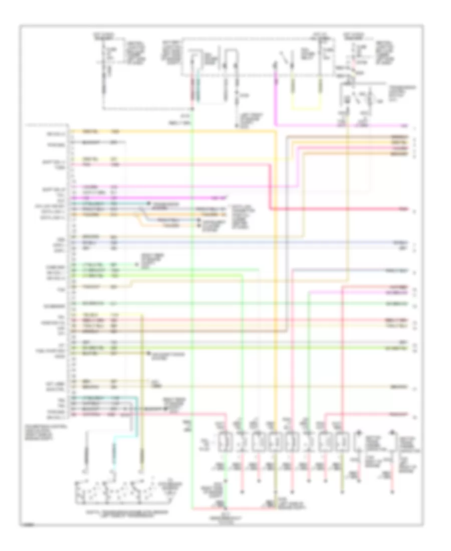
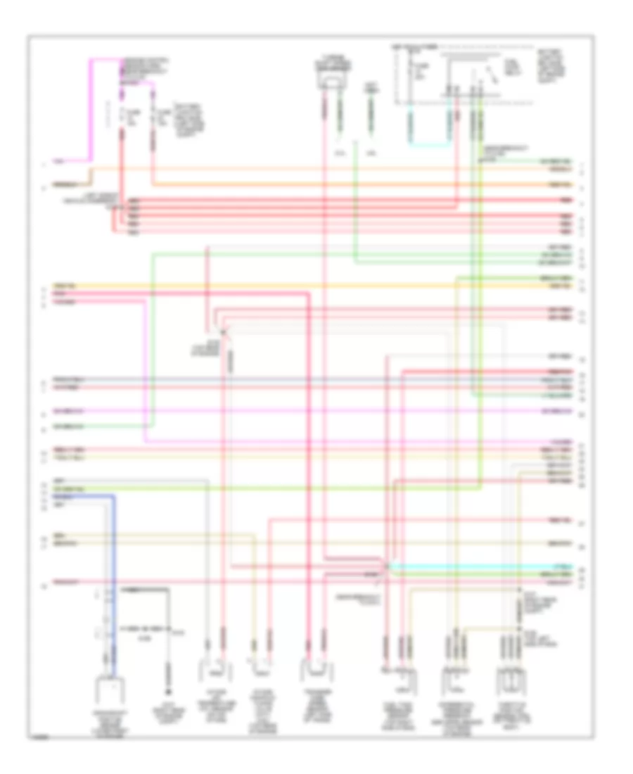
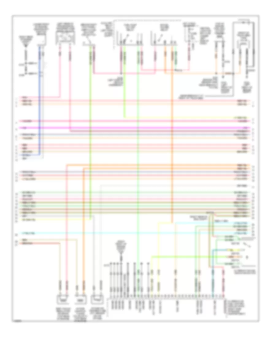
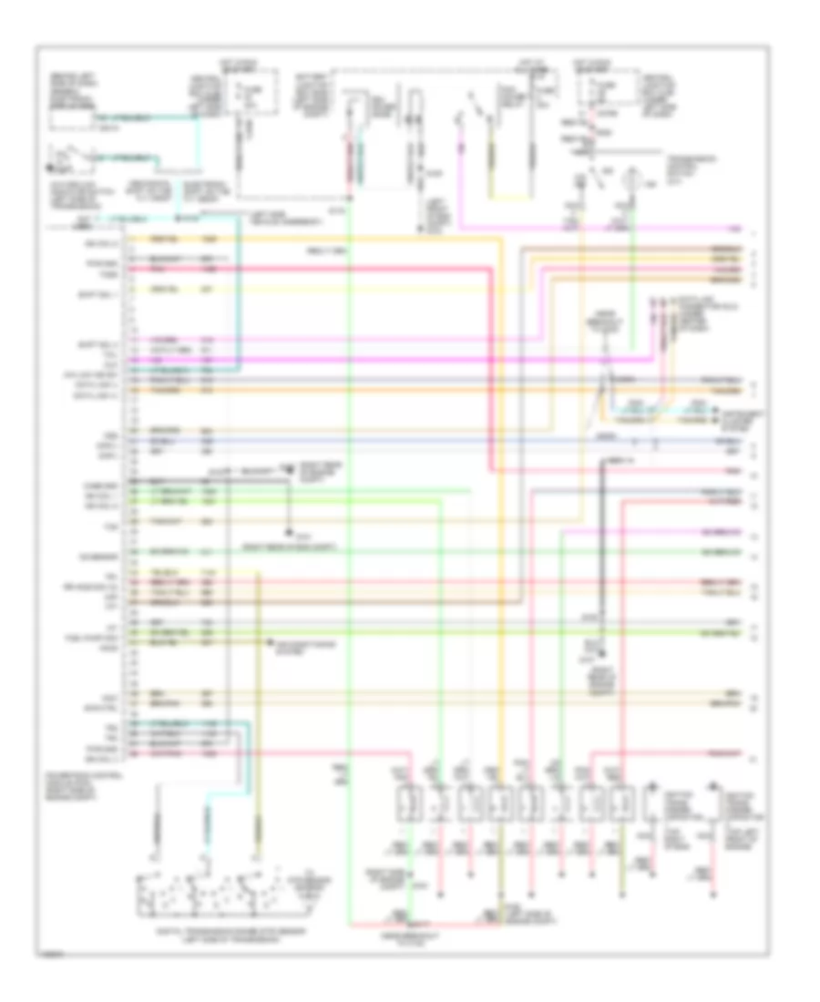
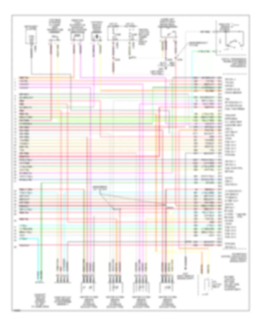
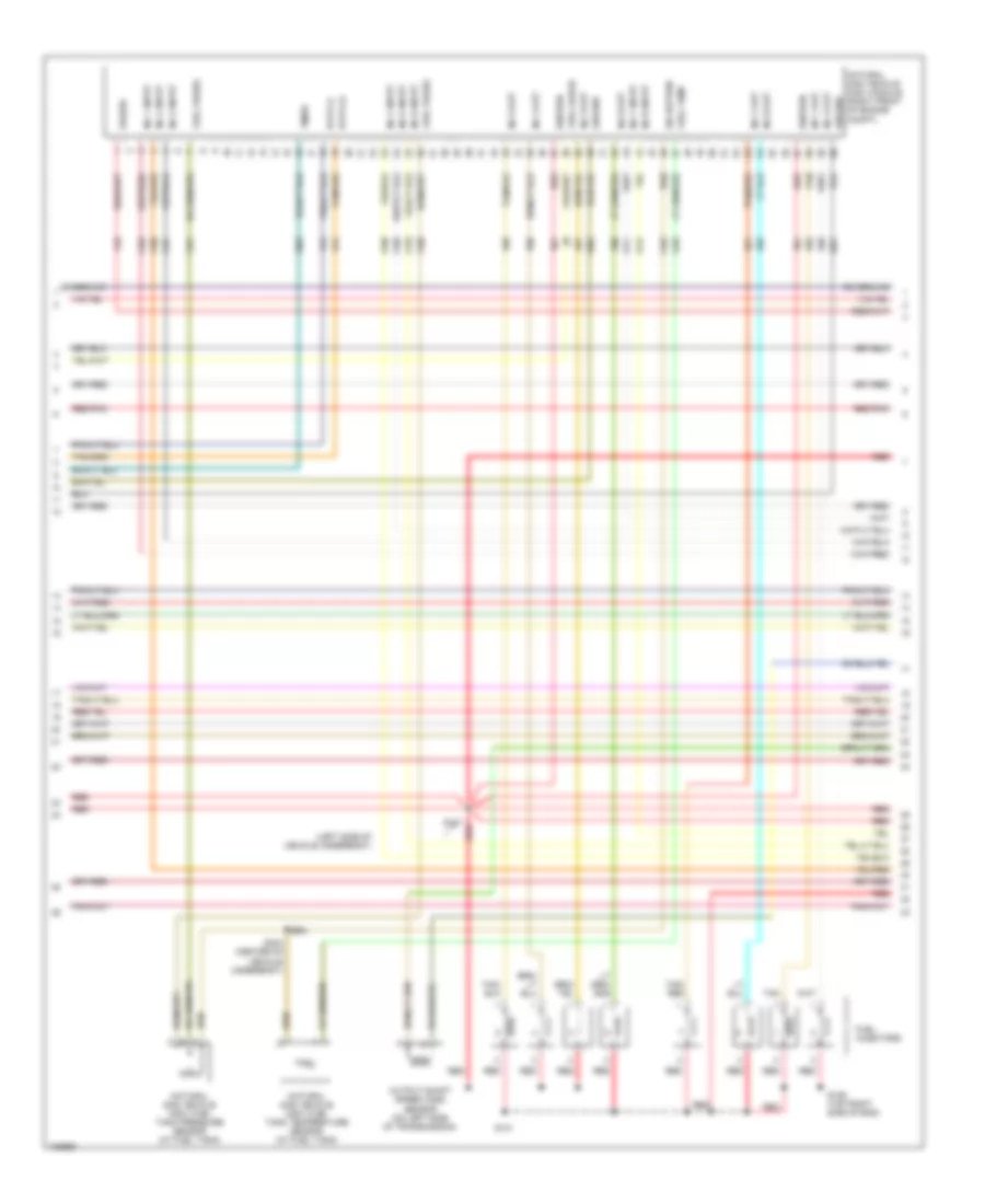
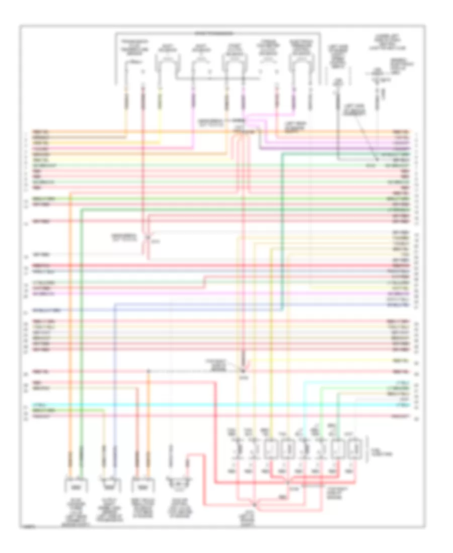
4.2L, Engine Performance Wiring Diagram (1 of 4) for Ford Pickup Heritage F150 2004
 https://portal-diagnostov.com/license.html
Automotive Electricians Portal FZCO
Automotive Electricians Portal FZCO
https://portal-diagnostov.com/license.html
https://portal-diagnostov.com/license.html
Automotive Electricians Portal FZCO
Automotive Electricians Portal FZCO
List of elements for 4.2L, Engine Performance Wiring Diagram (1 of 4) for Ford Pickup Heritage F150 2004:
- (left front of engine compartment)
- (right rear of engine compt)
- (right rear of engine compt) g101
- 4x4 low sw
- 820 ohms
- A/c system
- Accs
- B nca
- Battery junction box (bjb) (left side of engine compt)
- C243
- C270b
- Case gnd
- Central junction box (cjb) (under left side of dash)
- Ckp(+)
- Ckp(-)
- Data link (+)
- Data link (-)
- Data link connector (dlc) (partial) (under center of dash)
- Digital transmission range (dtr) sensor (left side of transmission)
- Dlc
- Evr ctrl
- Fuel pump mon
- Fuse 30a
- Fuse 5a
- G102 (right rear of engine compt)
- G104
- G107
- Ho2s (12)
- Hot at all times
- Hot in run or start
- Iat
- Ign coil 1
- Ign coil 2
- Ignition coil (top right side of eng)
- Ignition transformer capacitor 1 (top right side of eng)
- Imrc
- Instrument cluster system
- Intake manifold runner control (imrc) module (top rear of engine)
- Ks sensor
- Maf
- Nca
- O/d off
- Pcm power diode
- Pcm power relay
- Powertrain control module (pcm) (right side of engine compt)
- Pwr gnd
- R n
- S100
- S106
- S116
- S117 (near breakout to c133)
- S153
- S225
- Shift sol a
- Shift sol b
- Tcs
- Tft
- To dtr sensor (diagram 4 of 4)
- Tr1
- Tr2
- Tr4
- Transmission control indicator lamp
- Transmission control switch (a/t)
- Transmission system
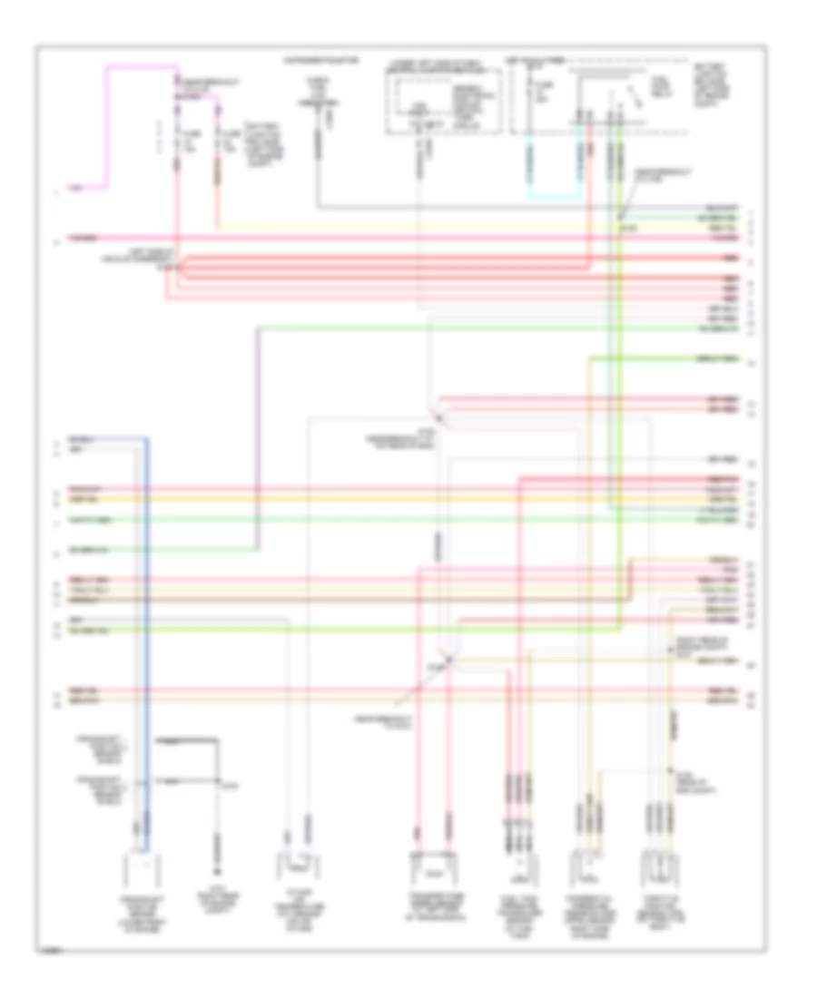
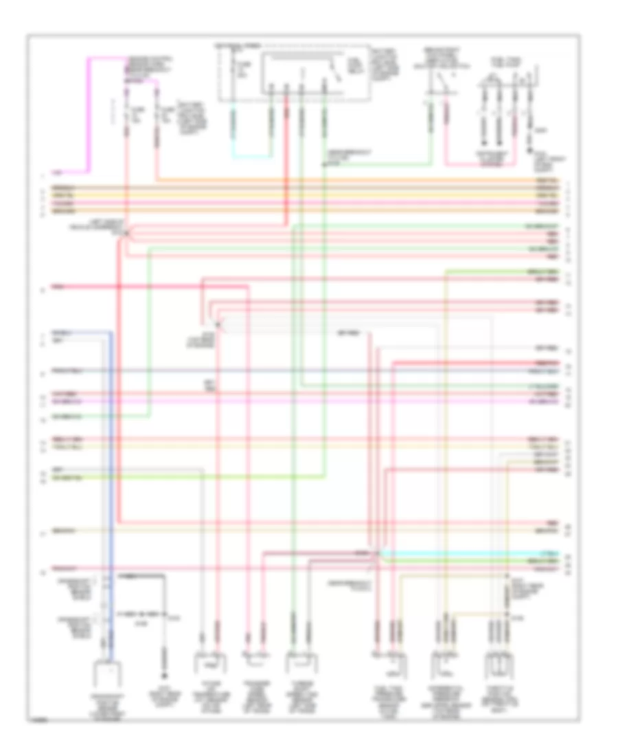
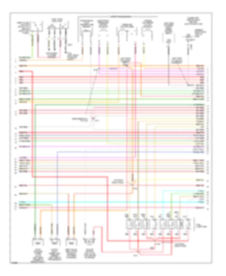
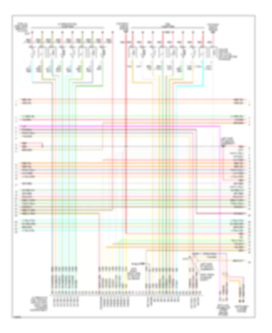
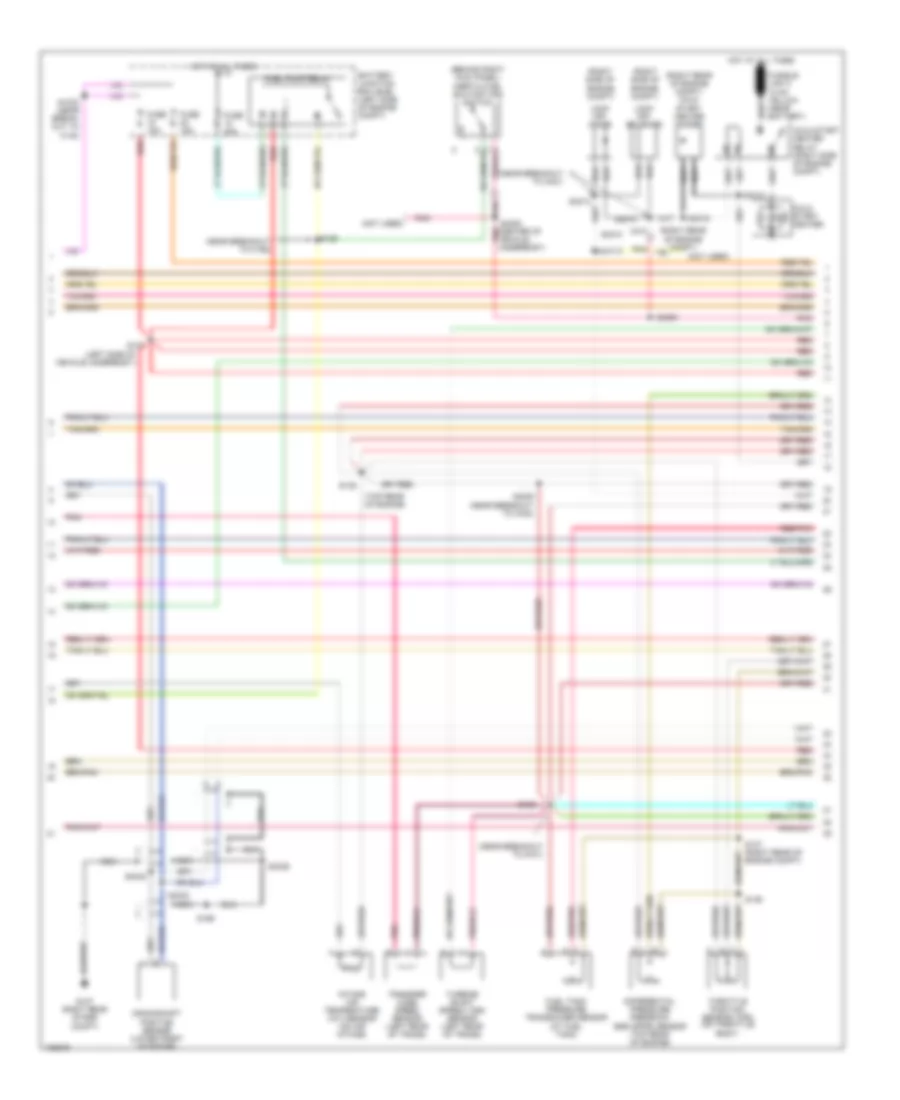
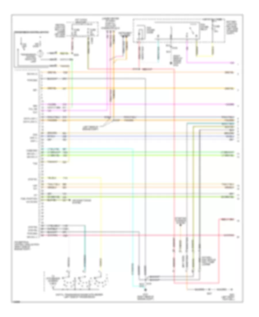
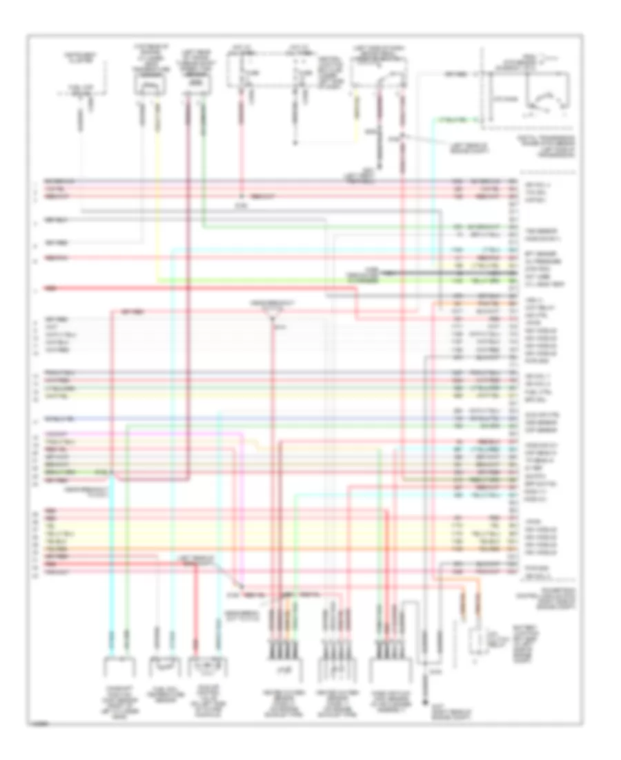
4.2L, Engine Performance Wiring Diagram (2 of 4) for Ford Pickup Heritage F150 2004
 https://portal-diagnostov.com/license.html
Automotive Electricians Portal FZCO
Automotive Electricians Portal FZCO
https://portal-diagnostov.com/license.html
https://portal-diagnostov.com/license.html
Automotive Electricians Portal FZCO
Automotive Electricians Portal FZCOList of elements for 4.2L, Engine Performance Wiring Diagram (2 of 4) for Ford Pickup Heritage F150 2004:
- (left side of vehicle underbody) s127
- (near breakout to c192)
- (near breakout to g101)
- (right rear of engine compt) s137
- (under left side of dash) central junction box (cjb)
- Battery junction box (bjb) (left side of engine compt)
- C201d
- C220a
- Check fuel cap indicator
- Crankshaft position sensor (lower front of engine)
- Crankshaft position sensor shield
- Differential pressure feedback egr (dpfe) sensor (right side of engine)
- Fuel pump relay
- Fuel tank pressure transducer sensor (at fuel tank)
- Fuse 15a
- Fuse 20a
- G107 (right rear of engine compt)
- Generic electronic module/ central timer module
- Hot at all times
- Instrument cluster
- Intake air temperature (iat) sensor (on air intake)
- Nca
- Pnk
- Red
- Red/pnk
- S100
- S135 (near breakout at top rear of eng)
- S136 (rear of eng compt)
- S138
- S139
- Throttle position sensor (tps) (on throttle body)
- Transfer case speed sensor (at left side of transmission)
- Vss input
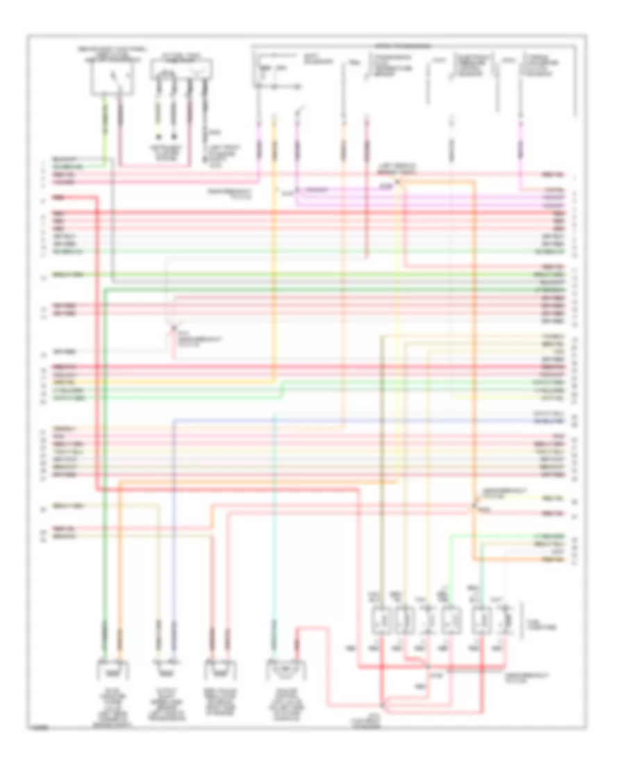
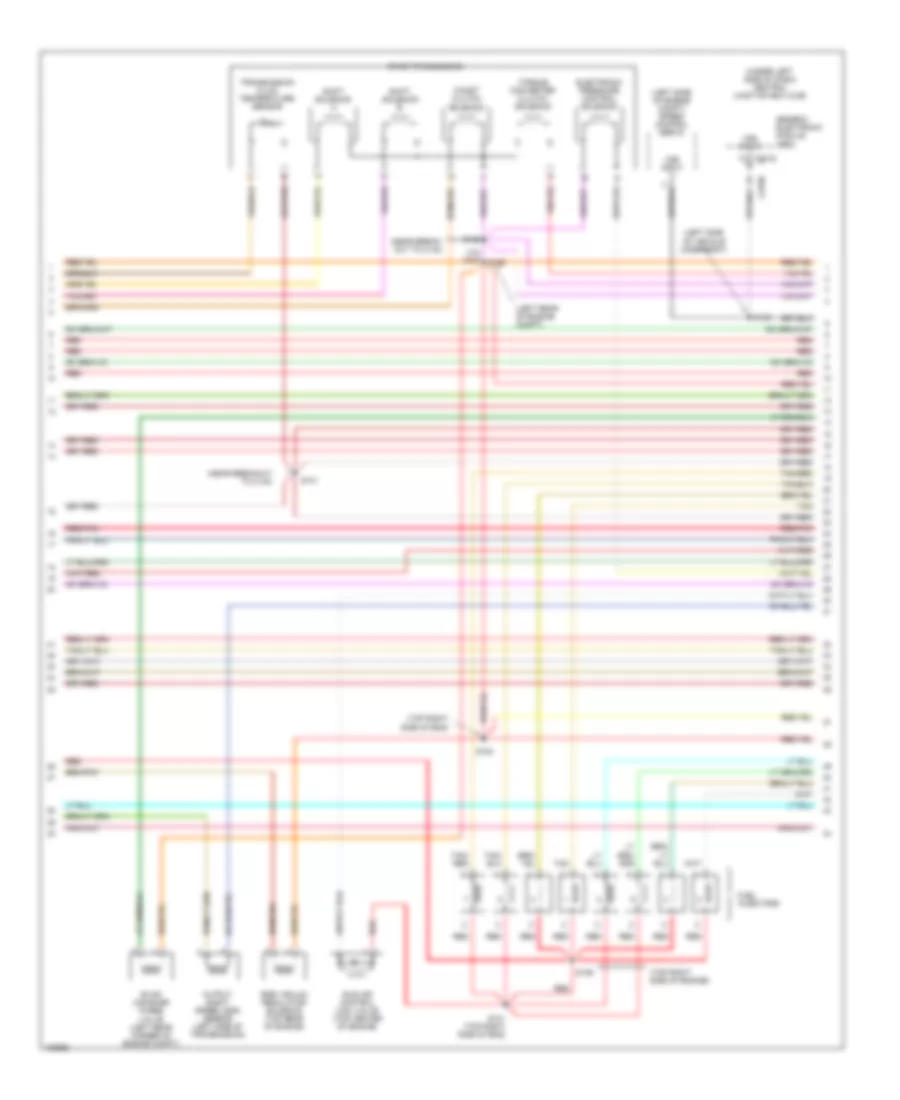
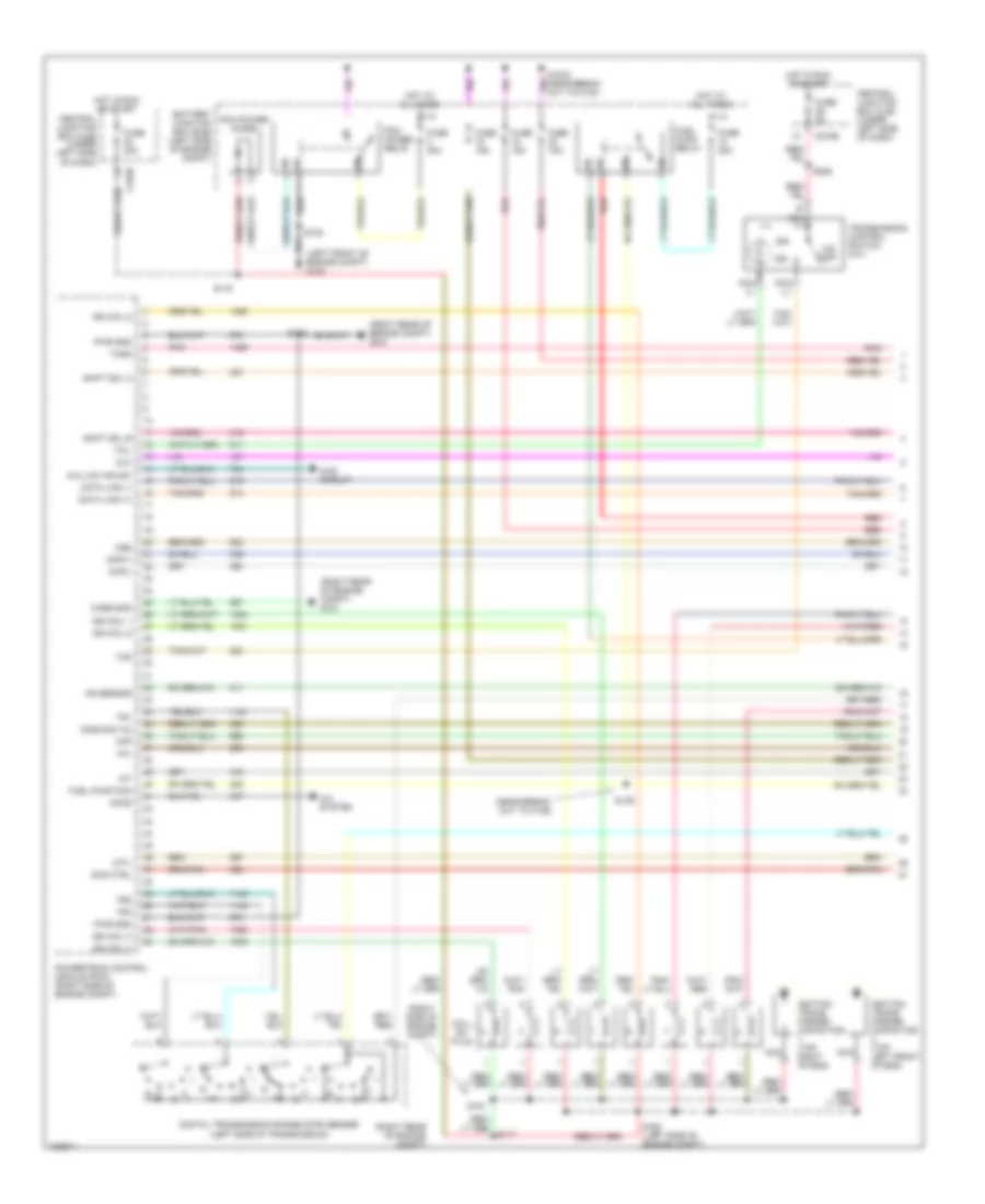
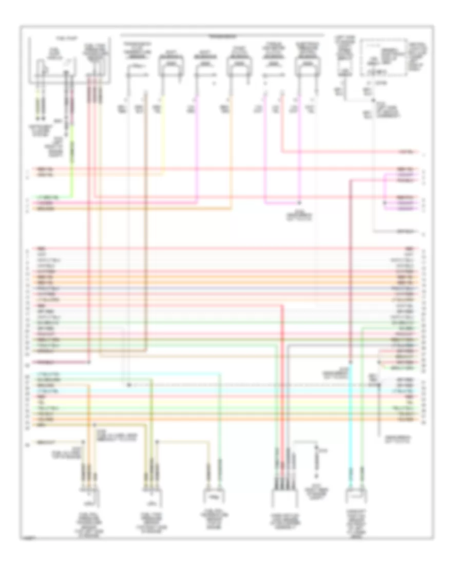
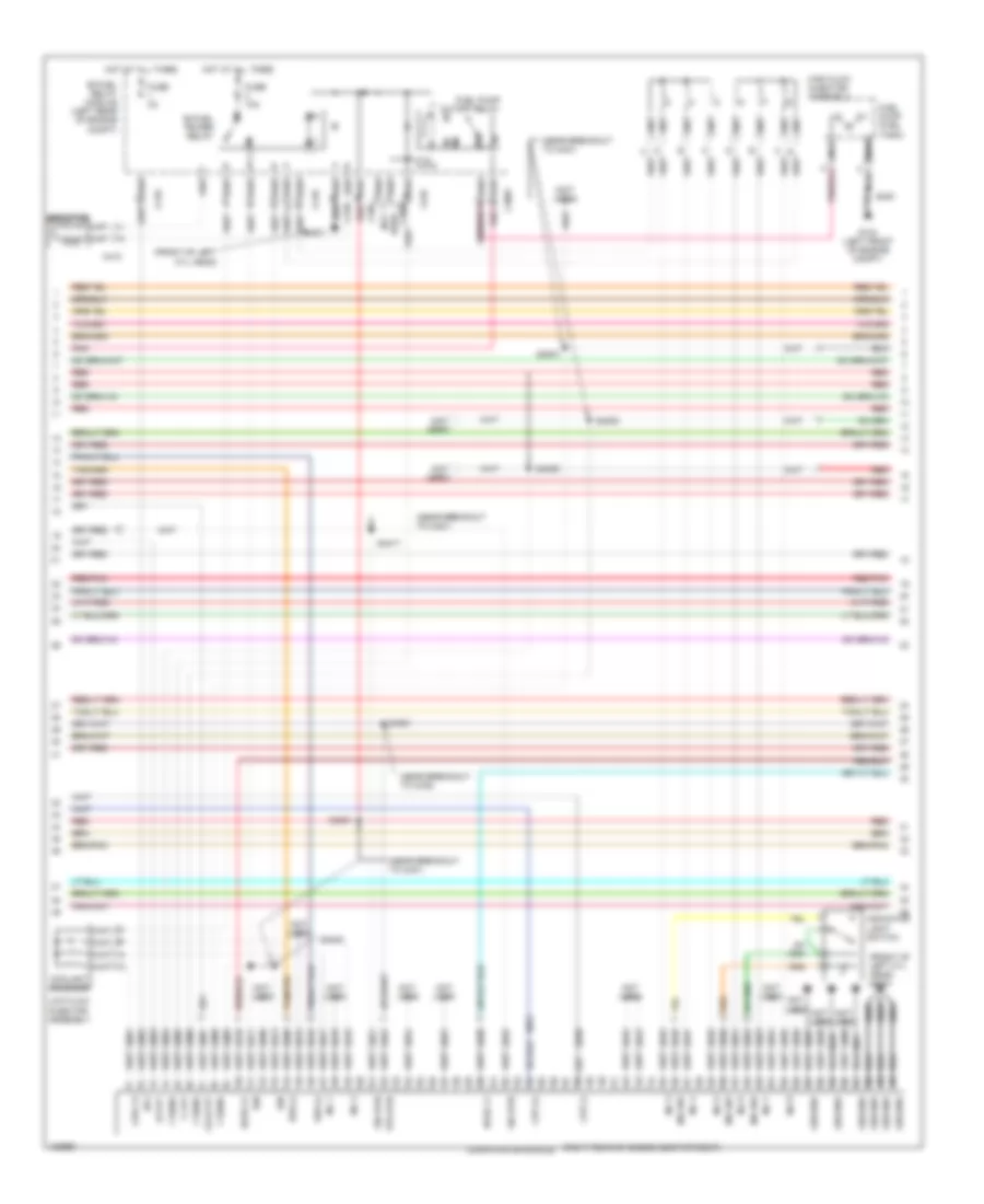
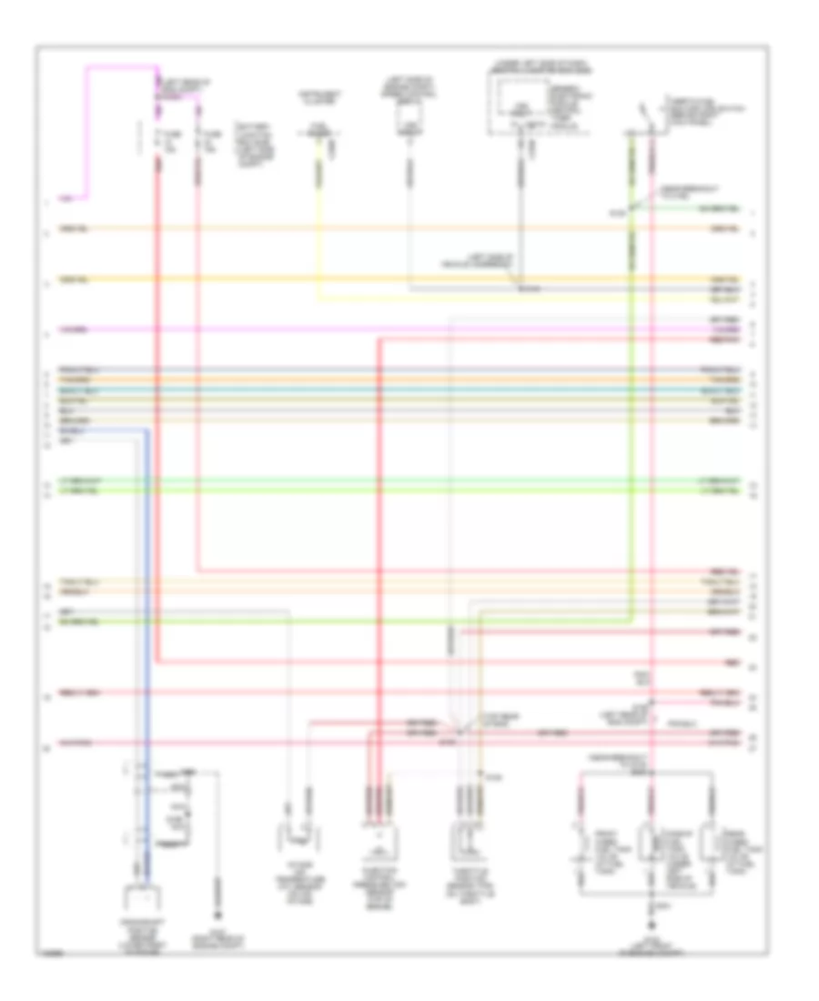
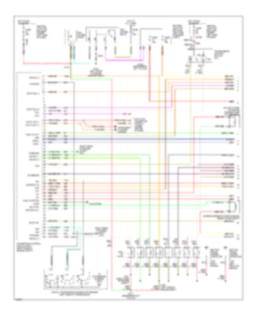
4.2L, Engine Performance Wiring Diagram (3 of 4) for Ford Pickup Heritage F150 2004
 https://portal-diagnostov.com/license.html
Automotive Electricians Portal FZCO
Automotive Electricians Portal FZCO
https://portal-diagnostov.com/license.html
https://portal-diagnostov.com/license.html
Automotive Electricians Portal FZCO
Automotive Electricians Portal FZCOList of elements for 4.2L, Engine Performance Wiring Diagram (3 of 4) for Ford Pickup Heritage F150 2004:
- (at fuel tank) fuel pump
- (behind right kick panel) inertia fuel shutoff (ifs) switch
- (left front of engine compt)
- (left rear of engine compt)
- (near breakout to c110)
- (near breakout to c133)
- 4r70w transmission
- Egr vacuum regulator solenoid (right side of engine)
- Electronic pressure control solenoid
- Evap canister purge
- Fuel injectors
- G104
- Idle air control (iac) valve (on left side of intake manifold)
- Instrument cluster system
- Nca
- Output shaft speed (oss) sensor (left side of transmission)
- Pnk
- Red
- Red/pnk
- S129
- S131 (top front of engine)
- S140
- S141 (near breakout to c110)
- S154
- S155
- S400
- Shift solenoids
- Ssa
- Ssb
- Tan
- Torque converter clutch solenoid
- Transmission fluid temperature sensor
- Valve (left rear corner of engine compt)
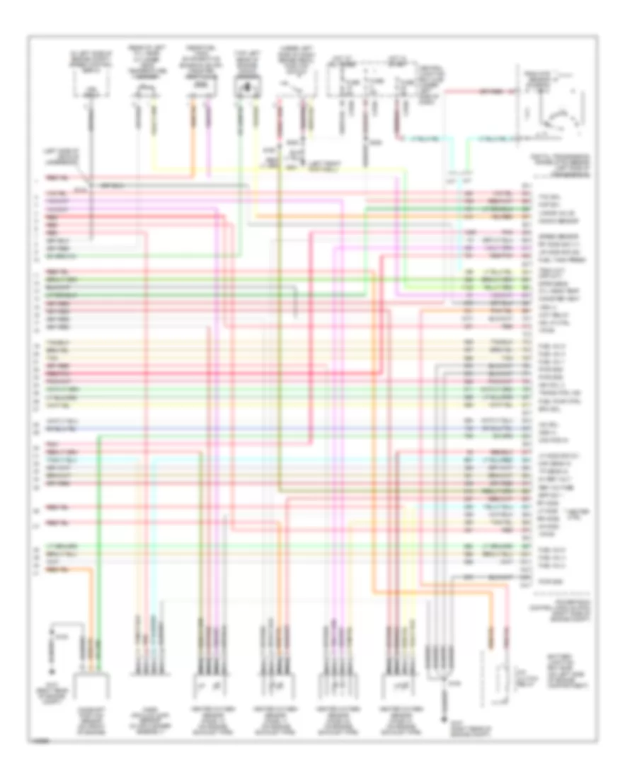
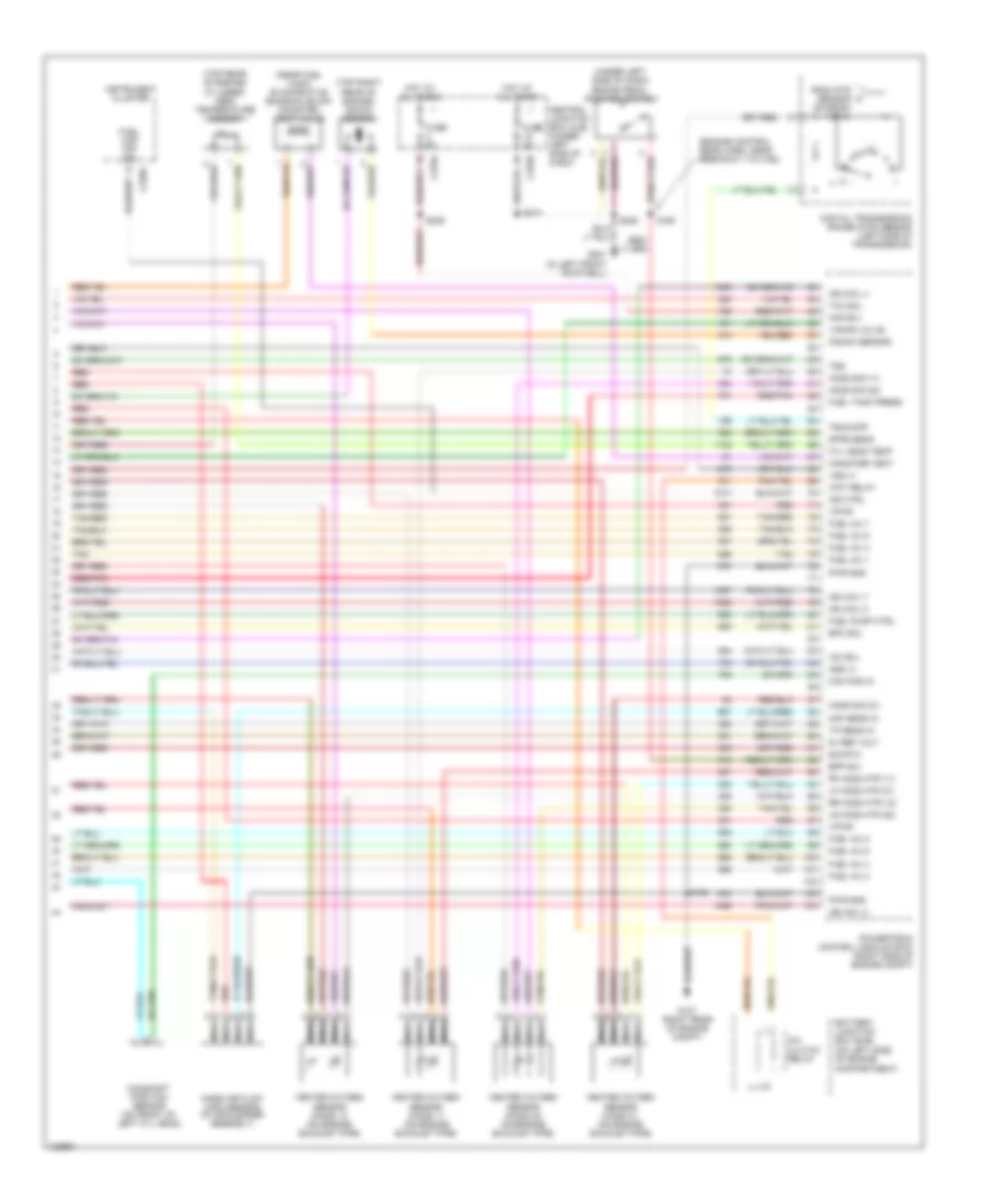
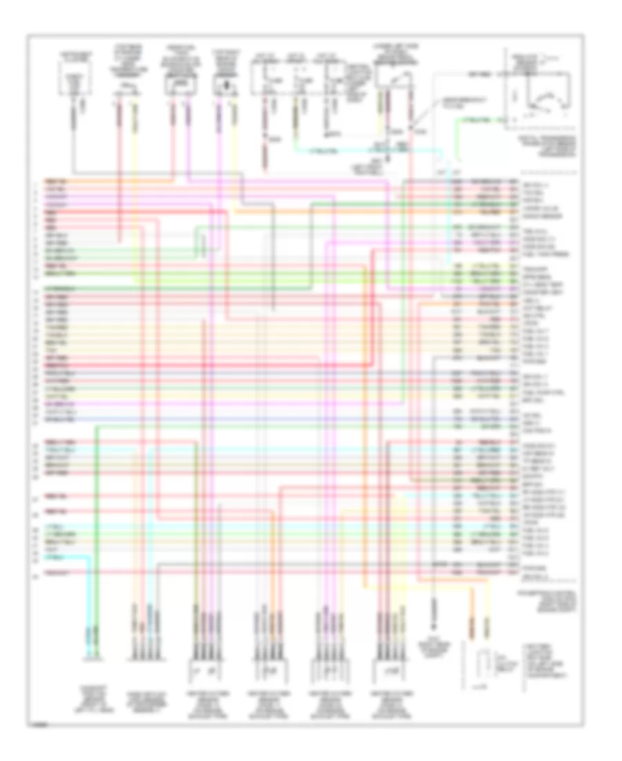
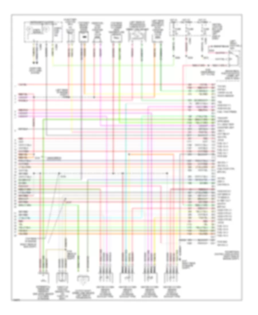
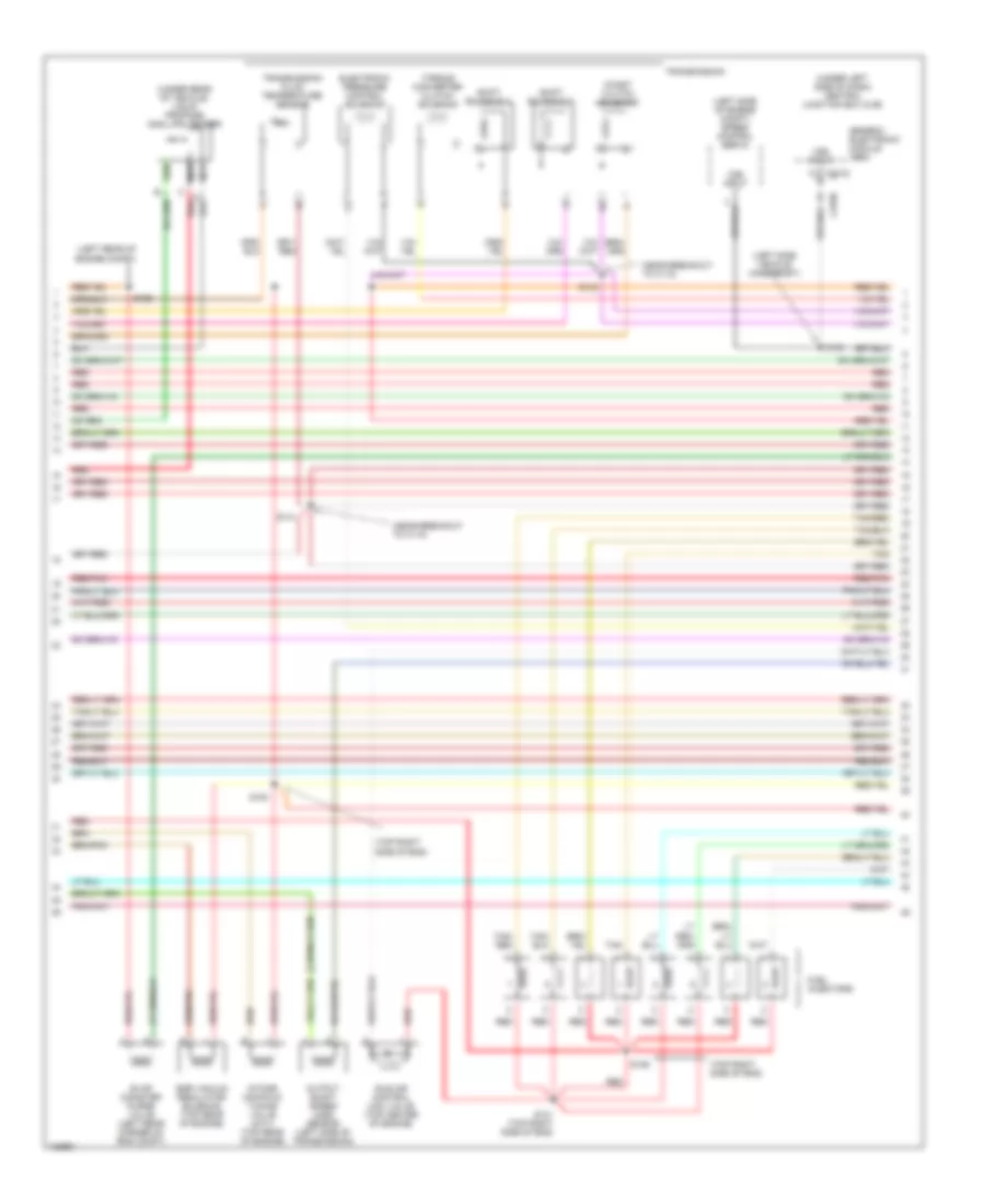
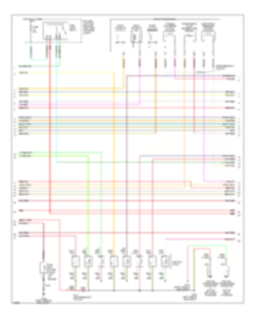
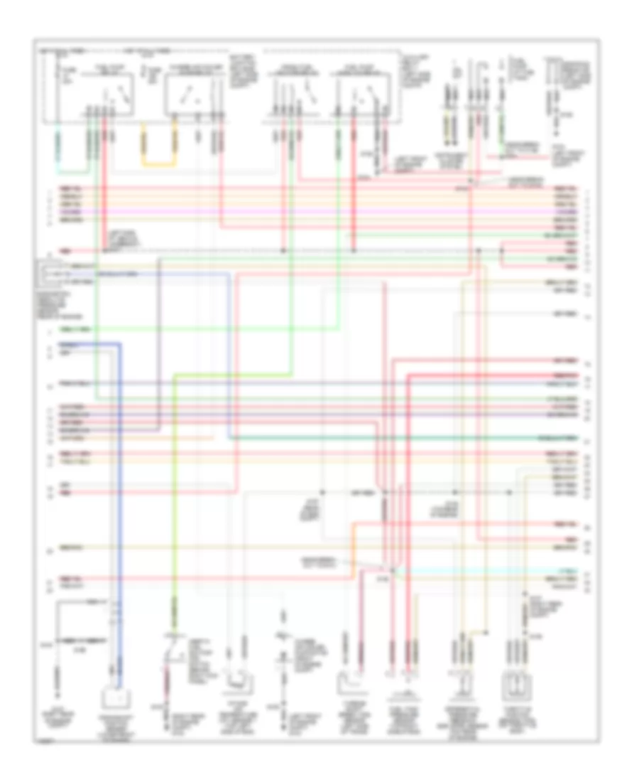
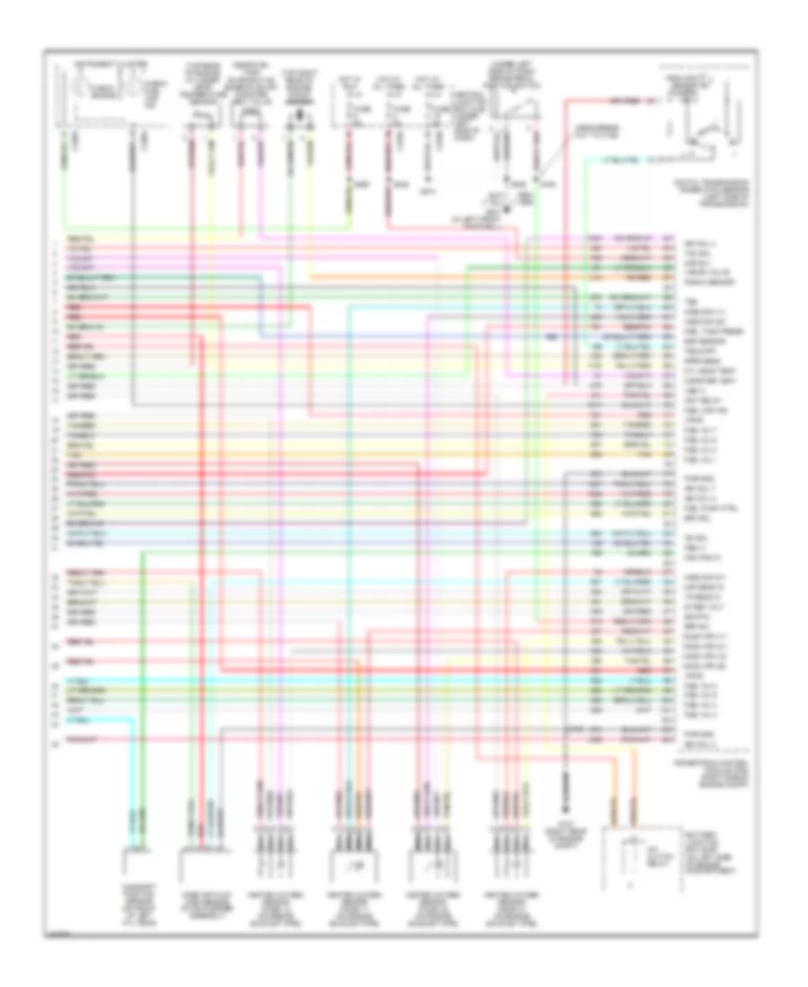
4.2L, Engine Performance Wiring Diagram (4 of 4) for Ford Pickup Heritage F150 2004
 https://portal-diagnostov.com/license.html
Automotive Electricians Portal FZCO
Automotive Electricians Portal FZCO
https://portal-diagnostov.com/license.html
https://portal-diagnostov.com/license.html
Automotive Electricians Portal FZCO
Automotive Electricians Portal FZCOList of elements for 4.2L, Engine Performance Wiring Diagram (4 of 4) for Ford Pickup Heritage F150 2004:
- (in left side of engine compt) speed control servo
- (left front footwell)
- (left side of vehicle underbody)
- (near fuel tank) evaporative emission (evap) canister vent valve
- (on left side of engine compartment)
- (rear of left cyl head) cylinder- head temperature sensor
- (top left rear of engine) knock sensor
- (under left side of dash) brake pedal position switch
- 5v ref volt
- A/c clutch relay
- A/t
- Battery junction box (bjb)
- Bpp sw
- C270a
- C270b
- Cam pos in
- Camshaft position sensor (on front of engine)
- Canister vent
- Central junction box (cjb) (under left side of dash)
- Cyl head temp
- Digital transmission range (dtr) sensor (left side of transmission)
- Dpfe sens
- Epc sol
- From dtr sensor (diagram 1 of 4)
- Fuel inj 1
- Fuel inj 2
- Fuel inj 3
- Fuel inj 4
- Fuel inj 5
- Fuel inj 6
- Fuel pump ctrl
- Fuel tank press
- Fuse 5a
- G107 (right rear of engine compt)
- G107 (right rear of engine compt)
- G201
- Heated oxygen sensor (ho2s) 11 (on engine exhaust pipe)
- Heated oxygen sensor (ho2s) 12 (on engine exhaust pipe)
- Heated oxygen sensor (ho2s) 21 (on engine exhaust pipe)
- Heated oxygen sensor (ho2s) 22 (on engine exhaust pipe)
- Heater ctrl
- Hot at all times
- Hot in start
- Iac sol
- Ign coil 3
- Ind lp ctrl
- Kap b(+)
- Knock sensor
- Lf ho2s
- Lf ho2s sig (21)
- Lr ho2s
- Lr ho2s sig (22)
- M/t
- Maf sens in
- Mass air flow (maf) sensor (in air cleaner assembly)
- Nca
- Oss (+)
- Pnk
- Powertrain control module (pcm) (right side of engine compt)
- Pwr gnd
- Red
- Red/pnk
- Ref voltage
- Rf ho2s
- Rf ho2s sig (11)
- Rr ho2s
- S100
- S143
- S160
- S208
- Speed sensor
- Tan
- Tcc sol
- Tp sens in
- Tr3a (a/t) cpp (m/t)
- Trans ctrl ind
- Vapor valve
- Vpwr
- Vss (+)
- Vss input
- Wot relay
4.6L
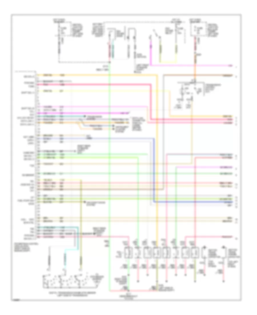
4.6L, Engine Performance Wiring Diagram (1 of 4) for Ford Pickup Heritage F150 2004
 https://portal-diagnostov.com/license.html
Automotive Electricians Portal FZCO
Automotive Electricians Portal FZCO
https://portal-diagnostov.com/license.html
https://portal-diagnostov.com/license.html
Automotive Electricians Portal FZCO
Automotive Electricians Portal FZCOList of elements for 4.6L, Engine Performance Wiring Diagram (1 of 4) for Ford Pickup Heritage F150 2004:
- (4.6l)
- (left front of engine compt) g104
- (right rear of engine compt) g101
- (right rear of engine compt) g107
- 4x4 low ind sw
- Accs
- Air conditioning system
- Battery junction box (bjb) (left side of engine compt)
- Capacitor (top left front of eng)
- Case gnd
- Central junction box (cjb) (under left side of dash)
- Ckp(+)
- Ckp(-)
- Coil on plug
- Data link (+)
- Data link (-)
- Data link connector (partial) (under center of dash)
- Digital transmission range (dtr) sensor (left side of transmission)
- Dlc
- Evr ctrl
- Fuel pump mon
- Fuse 30a
- Fuse 5a
- Ho2s sig (12)
- Hot at all times
- Hot in run or start
- Iat
- Ign coil 1
- Ign coil 3
- Ign coil 5
- Ign coil 6
- Ignition trans- former
- Ignition trans- former capacitor (top right of eng)
- Imcc
- Ind
- Instrument cluster system
- Ks sensor
- Maf
- Nca
- Not used
- O/d off
- Pcm power diode
- Pcm power relay
- Pnk
- Powertrain control module (pcm) (right side of engine compt)
- Pwr gnd
- R n
- S100
- S106 (or s105)
- S116
- S117 (near breakout to c133)
- S161 (right side of engine compt)
- S162 (left side of engine compt)
- Shift sol a
- Shift sol b
- Tcil
- Tcs
- Tcss
- Tft
- To dtr sensor (diagram 4 of 4)
- Tr1
- Tr2
- Tr4
- Transmission control switch (a/t)
- Transmission system
4.6L, Engine Performance Wiring Diagram (2 of 4) for Ford Pickup Heritage F150 2004
 https://portal-diagnostov.com/license.html
Automotive Electricians Portal FZCO
Automotive Electricians Portal FZCO
https://portal-diagnostov.com/license.html
https://portal-diagnostov.com/license.html
Automotive Electricians Portal FZCO
Automotive Electricians Portal FZCOList of elements for 4.6L, Engine Performance Wiring Diagram (2 of 4) for Ford Pickup Heritage F150 2004:
- (left side of vehicle underbody) s127
- (near breakout to c192) s139
- (near breakout to g101)
- (not used)
- 4.6l
- 5.4l
- Battery junction box (bjb) (left side of engine compt)
- Crankshaft position sensor (lower front of engine)
- Differential pressure feedback egr (dpfe) sensor (top rear of engine)
- Fuel pump relay
- Fuel tank pressure sensor (top right side of eng)
- Fuse 15a
- Fuse 20a
- G107 (right rear of engine compt)
- Hot at all times
- Intake air temperature (iat) sensor (on air intake)
- Intake manifold tuning valve (imtv) (4.6l) (top rear of engine)
- Nca
- Pnk
- Red
- Red/pnk
- S100
- S135 (top rear of engine)
- S136 (top left side of eng)
- S137 (right rear of engine compt)
- S138
- S199
- Throttle position sensor (tps) (on throttle body)
- Transfer case speed sensor (left side of trans)
- Turbine shaft speed (tss) sensor
4.6L, Engine Performance Wiring Diagram (3 of 4) for Ford Pickup Heritage F150 2004
 https://portal-diagnostov.com/license.html
Automotive Electricians Portal FZCO
Automotive Electricians Portal FZCO
https://portal-diagnostov.com/license.html
https://portal-diagnostov.com/license.html
Automotive Electricians Portal FZCO
Automotive Electricians Portal FZCOList of elements for 4.6L, Engine Performance Wiring Diagram (3 of 4) for Ford Pickup Heritage F150 2004:
- (fuel tank) fuel pump
- (left rear of engine compt) s155
- (left side of engine compt) speed control servo
- (left side of vehicle underbody
- (near breakout to c110)
- (top right side of eng)
- (under left side of dash) central junction box (cjb)
- 4r70w transmission
- C201d
- Egr vacuum regulator solenoid (top rear of engine)
- Electronic pressure control solenoid
- Evap canister purge
- Fuel injectors
- G104 (left front of engine compt)
- Generic electronic module (gem)
- Idle air control (iac) valve (top center of engine)
- Inertia fuel shutoff (ifs) switch (behind right kick panel)
- Instrument cluster system
- Nca
- Output shaft speed (oss) sensor (left side of transmission)
- Pressure controllers
- Red
- Red/pnk
- S129
- S131
- S140
- S141
- S143
- S154
- S400
- Tan
- Tan/ red
- Tan/red
- Torque converter clutch solenoid
- Transmission fluid temperature sensor
- Valve (left rear corner of engine compt)
- Vss input
4.6L, Engine Performance Wiring Diagram (4 of 4) for Ford Pickup Heritage F150 2004
 https://portal-diagnostov.com/license.html
Automotive Electricians Portal FZCO
Automotive Electricians Portal FZCO
https://portal-diagnostov.com/license.html
https://portal-diagnostov.com/license.html
Automotive Electricians Portal FZCO
Automotive Electricians Portal FZCOList of elements for 4.6L, Engine Performance Wiring Diagram (4 of 4) for Ford Pickup Heritage F150 2004:
- (5.4l)
- (near breakout to c192)
- (near fuel tank) evaporative emission evap) canister vent valve
- (on left side of engine compartment)
- (top rear of engine) cylinder- head temperature sensor
- (top right rear of engine) knock sensor
- (under left side of dash) brake pedal position switch
- 5v ref volt
- A/c clutch relay
- A/t
- Battery junction box (bjb)
- Bpp sw
- Cam pos in
- Camshaft position sensor (front of left cyl head)
- Canister vent
- Central junction box (cjb) (under left side of dash)
- Check fuel cap ind
- Cyl head temp
- Digital transmission range (dtr) sensor (left side of transmission)
- Dpfe sens
- Epc sol
- From dtr sensor (diagram 1 of 4)
- Fuel inj 1
- Fuel inj 2
- Fuel inj 3
- Fuel inj 4
- Fuel inj 5
- Fuel inj 6
- Fuel inj 7
- Fuel inj 8
- Fuel pump ctrl
- Fuel tank press
- Fuse 5a
- G107 (right rear of engine compt)
- G201 (left front footwell)
- Heated oxygen sensor (ho2s) 11 (on engine exhaust pipe)
- Heated oxygen sensor (ho2s) 12 (on engine exhaust pipe)
- Heated oxygen sensor (ho2s) 21 (on engine exhaust pipe)
- Heated oxygen sensor (ho2s) 22 (on engine exhaust pipe)
- Ho2s sig (11)
- Ho2s sig (21)
- Ho2s sig (22)
- Hot at all times
- Hot in start
- Iac sol
- Ign coil 2
- Ign coil 4
- Ign coil 7
- Ign coil 8
- Ind ctrl
- Instrument cluster
- Kap b(+)
- Knock sensor
- Lf ho2s htr (21)
- Lr ho2s htr (22)
- M/t
- Maf sens in
- Mass air flow (maf) sensor (in air cleaner assembly)
- Nca
- Oss (+)
- Powertrain control module (pcm) (right side of engine compt)
- Pwr gnd
- Red
- Red/pnk
- Rf ho2s htr (11)
- Rr ho2s htr (12)
- S100
- S160
- S208
- S236
- S274
- Sig rtn
- Tan
- Tan/red
- Tcc sol
- Tp sens in
- Tr3a/cpp
- Tss
- Vapor valve
- Vpwr
- Vss (+)
- Wot relay
5.4L
5.4L, Engine Performance Wiring Diagram, with 4R100 Transmission (1 of 4) for Ford Pickup Heritage F150 2004
 https://portal-diagnostov.com/license.html
Automotive Electricians Portal FZCO
Automotive Electricians Portal FZCO
https://portal-diagnostov.com/license.html
https://portal-diagnostov.com/license.html
Automotive Electricians Portal FZCO
Automotive Electricians Portal FZCOList of elements for 5.4L, Engine Performance Wiring Diagram, with 4R100 Transmission (1 of 4) for Ford Pickup Heritage F150 2004:
- (left front of engine compt) g104
- (right rear of engine compt) g101
- (right rear of engine compt) g107
- 4x4 low ind sw
- Accs
- Air conditioning system
- B nca
- Battery junction box (bjb) (left side of engine compt)
- C270b
- Capacitor (top left front of engine)
- Case gnd
- Central junction box (cjb) (under left side of dash)
- Ckp(+)
- Ckp(-)
- Coil on plug
- Css
- Data link (+)
- Data link (-)
- Data link connector (partial) (under center of dash)
- Digital transmission range (dtr) sensor (left side of transmission)
- Dlc
- Evr ctrl
- Fuel pump mon
- Fuse 30a
- Fuse 5a
- Ho2s sig (12)
- Hot at all times
- Hot in run or start
- Iat
- Ign coil 1
- Ign coil 3
- Ign coil 5
- Ign coil 6
- Ignition trans- former
- Ignition trans- former capacitor (top right of engine)
- Ind
- Instrument cluster system
- Ks sensor
- Maf
- Nca
- Not used
- O/d off
- Pcm power diode
- Pcm power relay
- Pnk
- Powertrain control module (pcm) (right side of engine compt)
- Pwr gnd
- R n
- S100
- S105
- S116
- S117 (near breakout to c133)
- S161 (right side of engine compt)
- S162 (left side of engine compt)
- S225
- Shift sol a
- Shift sol b
- Tcil
- Tcs
- Tcss
- Tft
- To dtr sensor (diagram 4 of 4)
- Tr1
- Tr2
- Tr4
- Transmission control switch (a/t)
- Transmission system
5.4L, Engine Performance Wiring Diagram, with 4R100 Transmission (2 of 4) for Ford Pickup Heritage F150 2004
 https://portal-diagnostov.com/license.html
Automotive Electricians Portal FZCO
Automotive Electricians Portal FZCO
https://portal-diagnostov.com/license.html
https://portal-diagnostov.com/license.html
Automotive Electricians Portal FZCO
Automotive Electricians Portal FZCOList of elements for 5.4L, Engine Performance Wiring Diagram, with 4R100 Transmission (2 of 4) for Ford Pickup Heritage F150 2004:
- (behind right kick panel) inertia fuel shutoff (ifs) switch
- (fuel tank) fuel pump
- (left side of vehicle underbody) s127
- (near breakout to c192) s139
- (near breakout to g101)
- Battery junction box (bjb) (left side of engine compt)
- Crankshaft position sensor (lower front of engine)
- Crankshaft position sensor shield
- Differential pressure feedback egr (dpfe) sensor (top rear of engine)
- Fuel pump relay
- Fuel tank pressure transducer sensor (in fuel tank)
- Fuse 15a
- Fuse 20a
- G104 (left front of eng compt)
- G107 (right rear of engine compt)
- Hot at all times
- Instrument cluster system
- Intake air temperature (iat) sensor (on air intake)
- Nca
- Pnk
- Red
- Red/pnk
- S100
- S135 (top rear of engine)
- S136
- S137 (right rear of engine compt)
- S138
- S199
- S400
- Throttle position sensor (tps) (on throttle body)
- Transfer case speed sensor (left rear of trans)
- Turbine shaft speed (tss) sensor (left side of trans)
5.4L, Engine Performance Wiring Diagram, with 4R100 Transmission (3 of 4) for Ford Pickup Heritage F150 2004
 https://portal-diagnostov.com/license.html
Automotive Electricians Portal FZCO
Automotive Electricians Portal FZCO
https://portal-diagnostov.com/license.html
https://portal-diagnostov.com/license.html
Automotive Electricians Portal FZCO
Automotive Electricians Portal FZCOList of elements for 5.4L, Engine Performance Wiring Diagram, with 4R100 Transmission (3 of 4) for Ford Pickup Heritage F150 2004:
- (left rear of engine compt)
- (left side of engine compt) speed control servo
- (left side of vehicle underbody)
- (near break- out to c140)
- (near breakout to c140)
- (top right side of eng)
- (top right side of engine)
- (under left side of dash) central junction box (cjb)
- 4r100 transmission
- C201d
- Coast clutch solenoid
- Egr vacuum regulator solenoid (top rear of engine)
- Electronic pressure control solenoid
- Evap canister purge
- Fuel injectors
- Generic electronic module (gem)
- Idle air control (iac) valve (top center of engine)
- Output shaft speed (oss) sensor (left side of transmission)
- Red
- Red/pnk
- S129
- S131 (top right side of eng)
- S140
- S141
- S143
- S154
- S155
- Shift solenoid a
- Shift solenoid b
- Tan
- Tan/ red
- Tan/red
- Torque converter clutch solenoid
- Transmission fluid temperature sensor
- Valve (left rear corner of engine compt)
- Vss input
5.4L, Engine Performance Wiring Diagram, with 4R100 Transmission (4 of 4) for Ford Pickup Heritage F150 2004
 https://portal-diagnostov.com/license.html
Automotive Electricians Portal FZCO
Automotive Electricians Portal FZCO
https://portal-diagnostov.com/license.html
https://portal-diagnostov.com/license.html
Automotive Electricians Portal FZCO
Automotive Electricians Portal FZCOList of elements for 5.4L, Engine Performance Wiring Diagram, with 4R100 Transmission (4 of 4) for Ford Pickup Heritage F150 2004:
- (engine control sens harn, near breakout to c192)
- (near fuel tank) evaporative emission (evap) canister vent valve
- (on left side of engine compartment)
- (top rear of engine) cylinder- head temperature sensor
- (top right rear of engine) knock sensor
- (under left side of dash) brake pedal position switch
- 5v ref volt
- A/c clutch relay
- Battery junction box (bjb)
- Bpp sw
- Cam pos in
- Camshaft position sensor (on front of left cyl head)
- Canister vent
- Central junction box (cjb) (under left side of dash)
- Cyl head temp
- Digital transmission range (dtr) sensor (left side of transmission)
- Dpfe sens
- Epc sol
- From dtr sensor (diagram 1 of 4)
- Fuel cap off ind
- Fuel inj 1
- Fuel inj 2
- Fuel inj 3
- Fuel inj 4
- Fuel inj 5
- Fuel inj 6
- Fuel inj 7
- Fuel inj 8
- Fuel pump ctrl
- Fuel tank press
- Fuse 5a
- G107 (right rear of engine compt)
- G201 (in left front footwell)
- Heated oxygen sensor (ho2s) 11 (on engine exhaust pipe)
- Heated oxygen sensor (ho2s) 12 (on engine exhaust pipe)
- Heated oxygen sensor (ho2s) 21 (on engine exhaust pipe)
- Heated oxygen sensor (ho2s) 22 (on engine exhaust pipe)
- Ho2s sig (11)
- Ho2s sig (21)
- Ho2s sig (22)
- Hot at all times
- Iac sol
- Ign coil 2
- Ign coil 4
- Ign coil 7
- Ign coil 8
- Ind ctrl
- Instrument cluster
- Kap b(+)
- Knock sensor
- Lf ho2s htr (21)
- Lr ho2s htr (22)
- Maf sens in
- Mass air flow (maf) sensor (in air cleaner assembly)
- Nca
- Oss (+)
- Powertrain control module (pcm) (right side of engine compt)
- Pwr gnd
- Red
- Red/pnk
- Rf ho2s htr (11)
- Rr ho2s htr (12)
- S100
- S160
- S208
- S236
- S274
- Sig rtn
- Tan
- Tan/red
- Tcc sol
- Tp sens in
- Tr3a/cpp
- Tss
- Vapor valve
- Vpwr
- Vss (+)
- Wot relay
5.4L, Engine Performance Wiring Diagram, with 4R70W Transmission (1 of 4) for Ford Pickup Heritage F150 2004
 https://portal-diagnostov.com/license.html
Automotive Electricians Portal FZCO
Automotive Electricians Portal FZCO
https://portal-diagnostov.com/license.html
https://portal-diagnostov.com/license.html
Automotive Electricians Portal FZCO
Automotive Electricians Portal FZCOList of elements for 5.4L, Engine Performance Wiring Diagram, with 4R70W Transmission (1 of 4) for Ford Pickup Heritage F150 2004:
- (4.6l)
- (left front of engine compt) g104
- (right rear of engine compt) g101
- (right rear of engine compt) g107
- 4x4 low ind sw
- Accs
- Air conditioning system
- Battery junction box (bjb) (left side of engine compt)
- Capacitor (top left front of eng)
- Case gnd
- Central junction box (cjb) (under left side of dash)
- Ckp(+)
- Ckp(-)
- Coil on plug
- Data link (+)
- Data link (-)
- Data link connector (partial) (under center of dash)
- Digital transmission range (dtr) sensor (left side of transmission)
- Dlc
- Evr ctrl
- Fuel pump mon
- Fuse 30a
- Fuse 5a
- Ho2s sig (12)
- Hot at all times
- Hot in run or start
- Iat
- Ign coil 1
- Ign coil 3
- Ign coil 5
- Ign coil 6
- Ignition trans- former
- Ignition trans- former capacitor (top right of eng)
- Imcc
- Ind
- Instrument cluster system
- Ks sensor
- Maf
- Nca
- Not used
- O/d off
- Pcm power diode
- Pcm power relay
- Pnk
- Powertrain control module (pcm) (right side of engine compt)
- Pwr gnd
- R n
- S100
- S106 (or s105)
- S116
- S117 (near breakout to c133)
- S161 (right side of engine compt)
- S162 (left side of engine compt)
- Shift sol a
- Shift sol b
- Tcil
- Tcs
- Tcss
- Tft
- To dtr sensor (diagram 4 of 4)
- Tr1
- Tr2
- Tr4
- Transmission control switch (a/t)
- Transmission system
5.4L, Engine Performance Wiring Diagram, with 4R70W Transmission (2 of 4) for Ford Pickup Heritage F150 2004
 https://portal-diagnostov.com/license.html
Automotive Electricians Portal FZCO
Automotive Electricians Portal FZCO
https://portal-diagnostov.com/license.html
https://portal-diagnostov.com/license.html
Automotive Electricians Portal FZCO
Automotive Electricians Portal FZCOList of elements for 5.4L, Engine Performance Wiring Diagram, with 4R70W Transmission (2 of 4) for Ford Pickup Heritage F150 2004:
- (left side of vehicle underbody) s127
- (near breakout to c192) s139
- (near breakout to g101)
- (not used)
- 4.6l
- 5.4l
- Battery junction box (bjb) (left side of engine compt)
- Crankshaft position sensor (lower front of engine)
- Differential pressure feedback egr (dpfe) sensor (top rear of engine)
- Fuel pump relay
- Fuel tank pressure sensor (top right side of eng)
- Fuse 15a
- Fuse 20a
- G107 (right rear of engine compt)
- Hot at all times
- Intake air temperature (iat) sensor (on air intake)
- Intake manifold tuning valve (imtv) (4.6l) (top rear of engine)
- Nca
- Pnk
- Red
- Red/pnk
- S100
- S135 (top rear of engine)
- S136 (top left side of eng)
- S137 (right rear of engine compt)
- S138
- S199
- Throttle position sensor (tps) (on throttle body)
- Transfer case speed sensor (left side of trans)
- Turbine shaft speed (tss) sensor
5.4L, Engine Performance Wiring Diagram, with 4R70W Transmission (3 of 4) for Ford Pickup Heritage F150 2004
 https://portal-diagnostov.com/license.html
Automotive Electricians Portal FZCO
Automotive Electricians Portal FZCO
https://portal-diagnostov.com/license.html
https://portal-diagnostov.com/license.html
Automotive Electricians Portal FZCO
Automotive Electricians Portal FZCOList of elements for 5.4L, Engine Performance Wiring Diagram, with 4R70W Transmission (3 of 4) for Ford Pickup Heritage F150 2004:
- (fuel tank) fuel pump
- (left rear of engine compt) s155
- (left side of engine compt) speed control servo
- (left side of vehicle underbody
- (near breakout to c110)
- (top right side of eng)
- (under left side of dash) central junction box (cjb)
- 4r70w transmission
- C201d
- Egr vacuum regulator solenoid (top rear of engine)
- Electronic pressure control solenoid
- Evap canister purge
- Fuel injectors
- G104 (left front of engine compt)
- Generic electronic module (gem)
- Idle air control (iac) valve (top center of engine)
- Inertia fuel shutoff (ifs) switch (behind right kick panel)
- Instrument cluster system
- Nca
- Output shaft speed (oss) sensor (left side of transmission)
- Pressure controllers
- Red
- Red/pnk
- S129
- S131
- S140
- S141
- S143
- S154
- S400
- Tan
- Tan/ red
- Tan/red
- Torque converter clutch solenoid
- Transmission fluid temperature sensor
- Valve (left rear corner of engine compt)
- Vss input
5.4L, Engine Performance Wiring Diagram, with 4R70W Transmission (4 of 4) for Ford Pickup Heritage F150 2004
 https://portal-diagnostov.com/license.html
Automotive Electricians Portal FZCO
Automotive Electricians Portal FZCO
https://portal-diagnostov.com/license.html
https://portal-diagnostov.com/license.html
Automotive Electricians Portal FZCO
Automotive Electricians Portal FZCOList of elements for 5.4L, Engine Performance Wiring Diagram, with 4R70W Transmission (4 of 4) for Ford Pickup Heritage F150 2004:
- (5.4l)
- (near breakout to c192)
- (near fuel tank) evaporative emission evap) canister vent valve
- (on left side of engine compartment)
- (top rear of engine) cylinder- head temperature sensor
- (top right rear of engine) knock sensor
- (under left side of dash) brake pedal position switch
- 5v ref volt
- A/c clutch relay
- A/t
- Battery junction box (bjb)
- Bpp sw
- Cam pos in
- Camshaft position sensor (front of left cyl head)
- Canister vent
- Central junction box (cjb) (under left side of dash)
- Check fuel cap ind
- Cyl head temp
- Digital transmission range (dtr) sensor (left side of transmission)
- Dpfe sens
- Epc sol
- From dtr sensor (diagram 1 of 4)
- Fuel inj 1
- Fuel inj 2
- Fuel inj 3
- Fuel inj 4
- Fuel inj 5
- Fuel inj 6
- Fuel inj 7
- Fuel inj 8
- Fuel pump ctrl
- Fuel tank press
- Fuse 5a
- G107 (right rear of engine compt)
- G201 (left front footwell)
- Heated oxygen sensor (ho2s) 11 (on engine exhaust pipe)
- Heated oxygen sensor (ho2s) 12 (on engine exhaust pipe)
- Heated oxygen sensor (ho2s) 21 (on engine exhaust pipe)
- Heated oxygen sensor (ho2s) 22 (on engine exhaust pipe)
- Ho2s sig (11)
- Ho2s sig (21)
- Ho2s sig (22)
- Hot at all times
- Hot in start
- Iac sol
- Ign coil 2
- Ign coil 4
- Ign coil 7
- Ign coil 8
- Ind ctrl
- Instrument cluster
- Kap b(+)
- Knock sensor
- Lf ho2s htr (21)
- Lr ho2s htr (22)
- M/t
- Maf sens in
- Mass air flow (maf) sensor (in air cleaner assembly)
- Nca
- Oss (+)
- Powertrain control module (pcm) (right side of engine compt)
- Pwr gnd
- Red
- Red/pnk
- Rf ho2s htr (11)
- Rr ho2s htr (12)
- S100
- S160
- S208
- S236
- S274
- Sig rtn
- Tan
- Tan/red
- Tcc sol
- Tp sens in
- Tr3a/cpp
- Tss
- Vapor valve
- Vpwr
- Vss (+)
- Wot relay
5.4L BI-FUEL GAS/CNG
5.4L Bi-Fuel Gas/CNG, Engine Performance Wiring Diagram (1 of 5) for Ford Pickup Heritage F150 2004
 https://portal-diagnostov.com/license.html
Automotive Electricians Portal FZCO
Automotive Electricians Portal FZCO
https://portal-diagnostov.com/license.html
https://portal-diagnostov.com/license.html
Automotive Electricians Portal FZCO
Automotive Electricians Portal FZCOList of elements for 5.4L Bi-Fuel Gas/CNG, Engine Performance Wiring Diagram (1 of 5) for Ford Pickup Heritage F150 2004:
- (left front of engine compt) g104
- (near break- out to c192)
- (right rear of engine compt)
- (right rear of engine compt) g101
- (right rear of engine compt) g107
- (right side of engine compt)
- 4wd circuit
- 4x4 low ind sw
- A/c system
- Accs
- Battery junction box (bjb) (left side of engine compt)
- C270b
- Case gnd
- Central junction box (cjb) (under left side of dash)
- Ckp(+)
- Ckp(-)
- Coil on plug
- Css
- Data link (+)
- Data link (-)
- Digital transmission range (dtr) sensor (left side of transmission)
- Dlc
- Evr ctrl
- Fuel pump mon
- Fuel pump relay
- Fuse 15a
- Fuse 20a
- Fuse 30a
- Fuse 5a
- Ho2s sig (12)
- Hot at all times
- Hot in run or start
- Iat
- Ign coil 1
- Ign coil 3
- Ign coil 4
- Ign coil 5
- Ign coil 6
- Ignition trans- former capacitor (top left front of eng)
- Ignition trans- former capacitor (top right of eng)
- Imtv
- Ind
- Ks sensor
- Maf
- Nca
- O/d off
- Pcm power diode
- Pcm power relay
- Pnk
- Powertrain control module (pcm) (right side of engine compt)
- Pwr gnd
- R n
- Red
- S100
- S105
- S116
- S117
- S139
- S161
- S162 (left side of engine compt)
- S225
- Shift sol a
- Shift sol b
- Tcil
- Tcs
- Tcss
- Tft
- Tr1
- Tr2
- Tr4
- Transmission control switch (a/t)
5.4L Bi-Fuel Gas/CNG, Engine Performance Wiring Diagram (2 of 5) for Ford Pickup Heritage F150 2004
 https://portal-diagnostov.com/license.html
Automotive Electricians Portal FZCO
Automotive Electricians Portal FZCO
https://portal-diagnostov.com/license.html
https://portal-diagnostov.com/license.html
Automotive Electricians Portal FZCO
Automotive Electricians Portal FZCOList of elements for 5.4L Bi-Fuel Gas/CNG, Engine Performance Wiring Diagram (2 of 5) for Ford Pickup Heritage F150 2004:
- (behind right kick panel) inertia fuel shutoff (ifs) switch
- (front of truck bed) tank valve
- (left rear of transmission) transfer case speed sensor
- (lower front of engine) crankshaft position sensor
- (near breakout at front of truck bed)
- (pins 5-16 not used)
- (right front of engine compt) g108
- (right rear of eng compt)
- (right rear of engine compt) g107
- (right side of engine compartment)
- (top of engine) fuel rail cutoff valve
- (top rear of engine)
- 87a
- Alt fuel ind
- Alternative fuel control module (afcm)
- Alternative fuel indicator switch
- Auxiliary relay box 1 (left side of eng compt)
- Bi-fuel power relay
- Bi-fuel rly
- C2270a
- C2270b
- C2270c
- C2270d
- C270b
- Central junction box (cjb) (under left side of dash)
- Egr vacuum regulator solenoid
- Fuel pump
- Fuel pump cut-off relay
- Fuse 30a
- G104 (left front of engine compt)
- Ground
- Hot in run or start
- Intake air temperature (iat) sensor (on air intake)
- Intake manifold tuning valve (imtv) (top rear of engine)
- Nca
- Pnk
- Rail press
- Rail temp
- Red
- S100
- S116
- S175
- S177
- S189 (left side of vehicle underbody)
- S191 (engine ctrl sensor harn, near breakout to c192)
- S199
- S4023
- Start/run
- Tank press
5.4L Bi-Fuel Gas/CNG, Engine Performance Wiring Diagram (3 of 5) for Ford Pickup Heritage F150 2004
 https://portal-diagnostov.com/license.html
Automotive Electricians Portal FZCO
Automotive Electricians Portal FZCO
https://portal-diagnostov.com/license.html
https://portal-diagnostov.com/license.html
Automotive Electricians Portal FZCO
Automotive Electricians Portal FZCOList of elements for 5.4L Bi-Fuel Gas/CNG, Engine Performance Wiring Diagram (3 of 5) for Ford Pickup Heritage F150 2004:
- (fuel inj harn, near breakout to c1019)
- (left side of vehicle underbody)
- (left side of vehicle underbody) s127
- (right rear of engine compt)
- (right side of engine compartment)
- (top right side of engine) s129
- (top right side of engine) s131
- Alt inj 1
- Alt inj 2
- Alt inj 3
- Alt inj 4
- Alt inj 5
- Alt inj 6
- Alt inj 7
- Alt inj 8
- Alternate fuel injectors
- Alternative fuel control module (afcm)
- Data link connector (under center of dash)
- Fuel injectors
- G103 (right front side of vehicle exterior)
- Ground
- Idle air control (iac) valve (on top center of engine)
- Inj 1
- Inj 2
- Inj 3
- Inj 4
- Inj 5
- Inj 6
- Inj 7
- Inj 8
- Instrument cluster system
- Pcm inj 1
- Pcm inj 2
- Pcm inj 3
- Pcm inj 4
- Pcm inj 5
- Pcm inj 6
- Pcm inj 7
- Pcm inj 8
- Red
- Ref volt
- S104
- S179
- S181
- S187
- Scp bus +
- Scp bus -
- Sig ret
- Start/run
- Tan
- Tan/ red
- Tan/red
5.4L Bi-Fuel Gas/CNG, Engine Performance Wiring Diagram (4 of 5) for Ford Pickup Heritage F150 2004
 https://portal-diagnostov.com/license.html
Automotive Electricians Portal FZCO
Automotive Electricians Portal FZCO
https://portal-diagnostov.com/license.html
https://portal-diagnostov.com/license.html
Automotive Electricians Portal FZCO
Automotive Electricians Portal FZCOList of elements for 5.4L Bi-Fuel Gas/CNG, Engine Performance Wiring Diagram (4 of 5) for Ford Pickup Heritage F150 2004:
- (left side of engine compt) speed control servo
- (near break- out to c110)
- C201d
- C270b
- Camshaft position sensor (on front of left cylinder head)
- Central junction box (cjb) (under left side of dash)
- Coast clutch solenoid
- Electronic pressure control solenoid
- Fuel pump
- Fuel pump module
- Fuel rail pressure transducer sensor (top left side of engine)
- Fuel rail temperature sensor (top of engine)
- Fuel tank pressure sensor (top right side of engine)
- Fuel tank pressure transducer sensor
- G104 (left front of engine compt)
- G107 (right rear of engine compt)
- Generic electronic module (gem)
- Instrument cluster system
- Mass air flow (maf) sensor (in air cleaner assembly)
- Nca
- Red
- Red/pnk
- S100
- S138 (near break- out to g101)
- S140 (near break- out to c110)
- S141
- S143 (left side of vehicle underbody)
- S183 (fuel inj harn, top of engine)
- S185 (fuel inj harn, near breakout to c1019)
- S400
- Shift solenoid a
- Shift solenoid b
- Torque converter clutch solenoid
- Transmission
- Transmission fluid temperature sensor
- Vss input
5.4L Bi-Fuel Gas/CNG, Engine Performance Wiring Diagram (5 of 5) for Ford Pickup Heritage F150 2004
 https://portal-diagnostov.com/license.html
Automotive Electricians Portal FZCO
Automotive Electricians Portal FZCO
https://portal-diagnostov.com/license.html
https://portal-diagnostov.com/license.html
Automotive Electricians Portal FZCO
Automotive Electricians Portal FZCOList of elements for 5.4L Bi-Fuel Gas/CNG, Engine Performance Wiring Diagram (5 of 5) for Ford Pickup Heritage F150 2004:
- (in battery junction box)
- (left front footwell) g201
- (left rear corner of eng compt) evap canister purge valve
- (left rear of engine compt) s155
- (left rear of transmission) turbine shaft speed (tss) sensor
- (near break- out to c110)
- (near fuel tank) evap canister vent valve
- (right rear of eng compt)
- (top rear of engine)
- (top rear of engine) cylinder- head temperature sensor
- (top right rear of engine) knock sensor
- 5v ref volt
- A/c clutch relay
- Bpp sw
- Brake pedal position switch (under left side of dash)
- C270a
- C270b
- Cam pos in
- Canister vent
- Central junction box (cjb) (under left side of dash)
- Check engine
- Check fuel cap ind
- Computer data lines system
- Cyl head temp
- Differential pressure feedback egr (dpfe) sensor (top rear of engine)
- Dpfe sens
- Epc sol
- Fuel inj 1
- Fuel inj 2
- Fuel inj 3
- Fuel inj 4
- Fuel inj 5
- Fuel inj 6
- Fuel inj 7
- Fuel inj 8
- Fuel pump ctrl
- Fuel tank press
- Fuse 5a
- G107 (right rear of engine compt)
- Heated oxygen sensor (ho2s) 11 (on engine exhaust pipe)
- Heated oxygen sensor (ho2s) 12 (on engine exhaust pipe)
- Heated oxygen sensor (ho2s) 21 (on engine exhaust pipe)
- Heated oxygen sensor (ho2s) 22 (on engine exhaust pipe)
- Ho2s htr (11)
- Ho2s htr (12)
- Ho2s htr (21)
- Ho2s htr (22)
- Ho2s sig (11)
- Ho2s sig (21)
- Ho2s sig (22)
- Hot at all times
- Hot in run
- Iac sol
- Ign coil 2
- Ign coil 7
- Ign coil 8
- Ind ctrl
- Instrument cluster
- Kap b(+)
- Knock sensor
- Maf sens in
- Nca
- Oss (+)
- Output shaft speed (oss) sensor (left side of transmission)
- Powertrain control module (pcm) (right side of engine compt)
- Pwr gnd
- Red
- Red/pnk
- S100
- S135
- S136 (rear of engine compt)
- S137
- S154
- S160 (near break- out to c192)
- S208
- S236
- S265
- S274
- Sig rtn
- Tcc sol
- Throttle position sensor (tps) (on throttle body)
- Tp sens in
- Tr3a/cpp
- Tss
- Vapor valve
- Vpwr
- Vss (+)
- Wot relay
5.4L BI-FUEL GAS/LPG
5.4L Bi-Fuel Gas/LPG, Engine Performance Wiring Diagram (1 of 5) for Ford Pickup Heritage F150 2004
 https://portal-diagnostov.com/license.html
Automotive Electricians Portal FZCO
Automotive Electricians Portal FZCO
https://portal-diagnostov.com/license.html
https://portal-diagnostov.com/license.html
Automotive Electricians Portal FZCO
Automotive Electricians Portal FZCOList of elements for 5.4L Bi-Fuel Gas/LPG, Engine Performance Wiring Diagram (1 of 5) for Ford Pickup Heritage F150 2004:
- (behind left side of dash) generic electronic module (gem)
- (left front of eng compt) g104
- (left side vehicle underbody)
- (near breakout to c133)
- (near breakout to c432)
- (right rear of eng compt)
- (right rear of engine compt)
- (right side of engine compt)
- 4x4 high/low indicator switch (left side of transmission)
- 4x4 low ind sw
- 4x2
- Accs
- Air conditioning system
- Battery junction box (bjb) (left side of engine compt)
- C201a
- C270b
- Case gnd
- Center of dash)
- Central junction box (cjb) (under left side of dash)
- Ckp(+)
- Ckp(-)
- Css
- Data link (+)
- Data link (-)
- Digital transmission range (dtr) sensor (left side of transmission)
- Dlc
- Electronic shift on the fly (esof)
- Evr ctrl
- Fuel pump mon
- Fuse 30a
- Fuse 5a
- G101
- G107
- Hot at all times
- Hot in run or start
- Iat
- Ign coil 1
- Ign coil 3
- Ign coil 5
- Ign coil 6
- Ignition trans- former capacitor (top left front of engine)
- Ignition trans- former capacitor (top right of eng)
- Imcc
- Ind
- Instrument cluster system
- Ks sensor
- Maf
- Mechanical shift on the fly (msof)
- Nca
- Not used
- O/d off
- Pcm power diode
- Pcm power relay
- Pnk
- Powertrain control module (pcm) (right side of engine compt)
- Pwr gnd
- R n
- Rr ho2s sig (12)
- S100
- S105
- S116
- S142
- S161
- S162 (left side of engine compt)
- S225
- S4003
- S4004
- Shift sol 1
- Shift sol 2
- Tcil
- Tcs
- Tcss
- Tft
- To dtr sensor (diagram 5 of 5)
- Tr1
- Tr2
- Tr4
- Transmission control switch (a/t)
5.4L Bi-Fuel Gas/LPG, Engine Performance Wiring Diagram (2 of 5) for Ford Pickup Heritage F150 2004
 https://portal-diagnostov.com/license.html
Automotive Electricians Portal FZCO
Automotive Electricians Portal FZCO
https://portal-diagnostov.com/license.html
https://portal-diagnostov.com/license.html
Automotive Electricians Portal FZCO
Automotive Electricians Portal FZCOList of elements for 5.4L Bi-Fuel Gas/LPG, Engine Performance Wiring Diagram (2 of 5) for Ford Pickup Heritage F150 2004:
- (behind right kick panel) inertia fuel shutoff (ifs) switch
- (left side of vehicle underbody)
- (near battery)
- (near breakout to c192)
- (near breakout to c421)
- (near breakout to g101)
- (not used)
- (right rear of engine compt)
- (right rear of engine compt) cold start heater diode
- (right side of engine compt)
- (top rear of engine)
- Battery junction box (bjb) (left side of engine compt)
- Cold start heater
- Cold start heater relay (right side of engine compt)
- Crankshaft position sensor (lower front of engine)
- Differential pressure feedback egr (dpfe) sensor (top rear of engine)
- Fuel pump relay
- Fuel tank pressure transducer sensor (at fuel tank)
- Fuse 15a
- Fuse 20a
- G107 (right rear of eng compt)
- Hot at all times
- Intake air temperature (iat) sensor (on air intake)
- Lock off diode
- Lock off solenoid
- Nca
- Pnk
- Pnk (center of vehicle underbody)
- Red
- Red/pnk
- S1003 (near break- out to c140)
- S127
- S135
- S136
- S137 (right rear of engine compt)
- S138
- S139
- S199
- S4005
- S4006
- S4010
- S4014
- S4015
- S4016
- S4020 (near breakout to c432)
- S4032
- S4033
- S4036
- Throttle position sensor (tps) (on throttle body)
- Transfer case speed sensor (left rear of trans)
- Turbine shaft speed (tss) sensor (left rear of trans)
5.4L Bi-Fuel Gas/LPG, Engine Performance Wiring Diagram (3 of 5) for Ford Pickup Heritage F150 2004
 https://portal-diagnostov.com/license.html
Automotive Electricians Portal FZCO
Automotive Electricians Portal FZCO
https://portal-diagnostov.com/license.html
https://portal-diagnostov.com/license.html
Automotive Electricians Portal FZCO
Automotive Electricians Portal FZCOList of elements for 5.4L Bi-Fuel Gas/LPG, Engine Performance Wiring Diagram (3 of 5) for Ford Pickup Heritage F150 2004:
- (b+)
- (front of left cyl head)
- (front of left cyl head) g4001
- (near breakout to c421)
- (near breakout to c432)
- (not used)
- (right rear of engine compartment)
- 1ooo
- 87a
- A pnk
- A red
- Bi-fuel power relay
- Bi-fuel relay module (left rear of engine compt)
- Bus (-)
- C4001
- C410
- C495
- Ckp (+)
- Ckp (-)
- Cold st
- Compuvalve module
- Cool s
- Coolant solenoid
- F cut
- F send
- Fuel pump (fuel tank)
- Fuel pump cutoff relay
- Fuse 10a
- Fuse 3a
- G001
- G002
- G003
- G004
- G005
- G006
- G007
- G008
- G009
- G010
- G011
- G013
- G015
- G016
- G017
- G018
- G019
- G021
- G022
- G024
- G027
- G030
- G032
- G038
- G042
- G043
- G045
- G046
- G047
- G049
- G050
- G051
- G052
- G053
- G054
- G055
- G056
- G057
- G058
- G059
- G060
- G061
- G062
- G063
- G064
- G086
- G096
- G104 (left front of engine compt)
- G4001
- G831
- Ground
- High flow injector assembly
- Ho2s 11
- Ho2s 21
- Hot at all times
- Ign
- Ind sw
- Indicator light switch
- Inj 1
- Inj 2
- Inj 3
- Inj 4
- Inj 5
- Inj 6
- Inj 7
- Inj 8
- Lk off
- Low flow injector assembly
- Nca
- Not used
- Not used c4000
- Pnk
- Red
- Red/pnk
- Resistor
- S400
- S4001
- S4007
- S4008
- S4009
- S4017
- S4021
- S4040
- Sig rtn
- Tps rtn
5.4L Bi-Fuel Gas/LPG, Engine Performance Wiring Diagram (4 of 5) for Ford Pickup Heritage F150 2004
 https://portal-diagnostov.com/license.html
Automotive Electricians Portal FZCO
Automotive Electricians Portal FZCO
https://portal-diagnostov.com/license.html
https://portal-diagnostov.com/license.html
Automotive Electricians Portal FZCO
Automotive Electricians Portal FZCOList of elements for 5.4L Bi-Fuel Gas/LPG, Engine Performance Wiring Diagram (4 of 5) for Ford Pickup Heritage F150 2004:
- (left rear of engine compt)
- (left side of engine compt) speed control servo
- (left side vehicle underbody)
- (near breakout to c110)
- (top right side of eng)
- (under left side of dash) central junction box (cjb)
- (under rear of vehicle) liquid propane gas (lpg) sender
- C201d
- Coast clutch solenoid
- Egr vacuum regulator solenoid (top rear of engine)
- Electronic pressure control solenoid
- Evap canister purge valve (left rear corner of eng compt)
- Fuel injectors
- Generic electronic module (gem)
- Idle air control (iac) valve (top center of engine)
- Intake manifold tuning valve (imtv) (top rear of engine)
- Nca
- Output shaft speed (oss) sensor (left side of transmission)
- Red
- Red/pnk
- S129
- S131 (top right side of eng)
- S140
- S141
- S143
- S154
- S155
- Shift solenoid 1
- Shift solenoid 2
- Tan
- Tan/ red
- Tan/red
- Torque converter clutch solenoid
- Transmission
- Transmission fluid temperature sensor
- Vss input
5.4L Bi-Fuel Gas/LPG, Engine Performance Wiring Diagram (5 of 5) for Ford Pickup Heritage F150 2004
 https://portal-diagnostov.com/license.html
Automotive Electricians Portal FZCO
Automotive Electricians Portal FZCO
https://portal-diagnostov.com/license.html
https://portal-diagnostov.com/license.html
Automotive Electricians Portal FZCO
Automotive Electricians Portal FZCOList of elements for 5.4L Bi-Fuel Gas/LPG, Engine Performance Wiring Diagram (5 of 5) for Ford Pickup Heritage F150 2004:
- (near break- out to c431)
- (near breakout to c192)
- (near fuel tank) evaporative emissions (evap) canister vent valve
- (on left side of engine compartment)
- (top rear of engine) cylinder- head temperature sensor
- (top right rear of engine) knock sensor
- (under left side of dash) brake pedal position switch
- 5v ref volt
- A/c clutch relay
- Battery junction box (bjb)
- Bpp sw
- Cam pos in
- Camshaft position sensor (on front of left cylinder head)
- Canister vent
- Central junction box (cjb) (under left side of dash)
- Cyl head temp
- Digital transmission range (dtr) sensor (left side of transmission)
- Dpfe sens
- Epc sol
- From dtr sensor (diagram 1 of 5)
- Fuel cap off ind
- Fuel inj 1
- Fuel inj 2
- Fuel inj 3
- Fuel inj 4
- Fuel inj 5
- Fuel inj 6
- Fuel inj 7
- Fuel inj 8
- Fuel pump ctrl
- Fuel tank press
- Fuse 5a
- G107 (right rear of engine compt)
- G201 (left front footwell)
- Heated oxygen sensor (ho2s) 11 (on engine exhaust pipe)
- Heated oxygen sensor (ho2s) 12 (on engine exhaust pipe)
- Heated oxygen sensor (ho2s) 21 (on engine exhaust pipe)
- Heated oxygen sensor (ho2s) 22 (on engine exhaust pipe)
- Heater ctrl
- Hot at all times
- Iac sol
- Ign coil 2
- Ign coil 4
- Ign coil 7
- Ign coil 8
- Ind ctrl
- Instrument cluster
- Kap b(+)
- Knock sensor
- Lf ho2s
- Lf ho2s sig (21)
- Lr ho2s
- Lr ho2s sig (22)
- Maf sens in
- Mass air flow (maf) sensor (in air cleaner assembly)
- Nca
- Oss (+)
- Powertrain control module (pcm) (right side of engine compt)
- Pwr gnd
- Red
- Red/pnk
- Rf ho2s
- Rf ho2s sig (11)
- Rr ho2s
- S100
- S160
- S208
- S236
- S274
- S4018
- S4019
- Sig rtn
- Tan
- Tan/red
- Tcc sol
- Tp sens in
- Tr3a/cpp
- Tss
- Vapor valve
- Vpwr
- Vss (+)
- Wot relay
5.4L CNG
5.4L CNG, Engine Performance Wiring Diagram (1 of 5) for Ford Pickup Heritage F150 2004
 https://portal-diagnostov.com/license.html
Automotive Electricians Portal FZCO
Automotive Electricians Portal FZCO
https://portal-diagnostov.com/license.html
https://portal-diagnostov.com/license.html
Automotive Electricians Portal FZCO
Automotive Electricians Portal FZCOList of elements for 5.4L CNG, Engine Performance Wiring Diagram (1 of 5) for Ford Pickup Heritage F150 2004:
- (left rear of engine compt)
- (not used)
- (right rear of engine compt) g102
- (under center of dash) (partial) datalink connector (dlc)
- A nca
- A/c on sig
- Air conditioning system
- Battery junction box (bjb) (left side of engine compt)
- C nca
- Case gnd
- Ccs
- Central junction box (cjb) (under left side of dash)
- Ckp (+)
- Ckp (-)
- Data link (+)
- Data link (-)
- Digital transmission range (dtr) sensor (left side of transmission)
- Dlc
- Dtr-tr1
- Dtr-tr2
- Dtr-tr4
- Fuel pump mon
- Fuse 30a
- Fuse 5a
- G107 (right rear of engine compt)
- G201 (left front footwell)
- Hot at all times
- Hot in run or start
- Iat
- Ign coil 1
- Ign coil 3
- Ign coil 5
- Ign coil 6
- Instrument cluster
- Maf
- Natural gas vehicle (ngv) timer jumper
- Nca
- O/d off
- Ohms
- Pcm power diode
- Pcm power relay
- Powertrain control module (pcm) (right side of engine compt)
- Pwr gnd
- R n
- S105
- S116
- S156
- S157
- S207
- S225
- Ss1
- Ss2
- Starting/ charging system
- Tan/red
- Tcil ind
- Tcs
- Tft
- To dtr sensor (diagram 5 of 5)
- Transmission control indicator lamp
- Transmission control switch
5.4L CNG, Engine Performance Wiring Diagram (2 of 5) for Ford Pickup Heritage F150 2004
 https://portal-diagnostov.com/license.html
Automotive Electricians Portal FZCO
Automotive Electricians Portal FZCO
https://portal-diagnostov.com/license.html
https://portal-diagnostov.com/license.html
Automotive Electricians Portal FZCO
Automotive Electricians Portal FZCOList of elements for 5.4L CNG, Engine Performance Wiring Diagram (2 of 5) for Ford Pickup Heritage F150 2004:
- (left side of engine compt) speed control servo
- (left side of vehicle underbody)
- (near breakout to c192)
- (near breakout to c315) s302
- (top rear of eng)
- (under left side of dash) central junction box (cjb)
- Battery junction box (bjb) (left side of engine compt)
- C201d
- C220b
- C270b
- Crankshaft position sensor (lower front of engine)
- Front in-bed fuel tank valve (at fuel tank)
- Fuel gauge
- Fuse 15a
- G104 (left front of engine coompt)
- G107 (right rear of engine compt)
- Generic electronic module/ central timer module
- Inertia fuel shutoff (ifs) switch (behind right kick panel)
- Injection control pressure (icp) sensor (top of engine)
- Instrument cluster
- Intake air temperature (iat) sensor (on air intake)
- Midship fuel tank valve (under left side of vehicle)
- Nca
- Rear in-bed fuel tank valve (at fuel tank)
- Red
- Red/pnk
- S100
- S135
- S136
- S139
- S143
- S159 (left rear of eng compt)
- S199
- S301
- Throttle position sensor (tps) (on throttle body)
- Vss input
5.4L CNG, Engine Performance Wiring Diagram (3 of 5) for Ford Pickup Heritage F150 2004
 https://portal-diagnostov.com/license.html
Automotive Electricians Portal FZCO
Automotive Electricians Portal FZCO
https://portal-diagnostov.com/license.html
https://portal-diagnostov.com/license.html
Automotive Electricians Portal FZCO
Automotive Electricians Portal FZCOList of elements for 5.4L CNG, Engine Performance Wiring Diagram (3 of 5) for Ford Pickup Heritage F150 2004:
- (near breakout to c110)
- 4r100 transmission
- Battery junction box (bjb) (left side of engine compt)
- Coast clutch solenoid
- Electronic pressure control solenoid
- Fuel pump relay
- Fuel rail cutoff valve (top of engine)
- Fuse 20a
- G102 (right rear of eng compt)
- Hot at all times
- Ignition coils
- Ignition transformer capacitor (on top left front of engine)
- Ignition transformer capacitor (on top right of engine)
- Nca
- Red
- Red red
- Red/pnk
- S117 (near breakout to c133)
- S140
- S153
- S161 (right side of eng compt)
- S162 (left side of eng compt)
- Shift solenoid
- Torque converter clutch solenoid
- Transmission fluid temperature sensor
5.4L CNG, Engine Performance Wiring Diagram (4 of 5) for Ford Pickup Heritage F150 2004
 https://portal-diagnostov.com/license.html
Automotive Electricians Portal FZCO
Automotive Electricians Portal FZCO
https://portal-diagnostov.com/license.html
https://portal-diagnostov.com/license.html
Automotive Electricians Portal FZCO
Automotive Electricians Portal FZCOList of elements for 5.4L CNG, Engine Performance Wiring Diagram (4 of 5) for Ford Pickup Heritage F150 2004:
- (left side of vehicle underbody)
- Data (+)
- Data (-)
- Fuel gauge
- Fuel injectors
- Fuel press
- Fuel temp
- Ground
- Ignition
- Inj 1 input
- Inj 1 out
- Inj 2 input
- Inj 2 out
- Inj 3 input
- Inj 3 out
- Inj 4 input
- Inj 4 out
- Inj 5 input
- Inj 5 out
- Inj 6 input
- Inj 6 out
- Inj 7 input
- Inj 7 out
- Inj 8 input
- Inj 8 out
- Natural gas vehicle (ngv) fuel tank pressure sensor (at fuel tank)
- Natural gas vehicle (ngv) fuel tank temperature sensor (at fuel tank)
- Natural gas vehicle (ngv) module (right front of engine compt)
- Output shaft speed (oss) sensor (on left side of transmission)
- Power
- Red
- Red/pnk
- S127
- S129 (top right side of eng)
- S131
- S303 (center of vehicle underbody)
- Sig return
- Tan
- Tan/ red
- Tan/red
- Timer
5.4L CNG, Engine Performance Wiring Diagram (5 of 5) for Ford Pickup Heritage F150 2004
 https://portal-diagnostov.com/license.html
Automotive Electricians Portal FZCO
Automotive Electricians Portal FZCO
https://portal-diagnostov.com/license.html
https://portal-diagnostov.com/license.html
Automotive Electricians Portal FZCO
Automotive Electricians Portal FZCOList of elements for 5.4L CNG, Engine Performance Wiring Diagram (5 of 5) for Ford Pickup Heritage F150 2004:
- (left rear of eng compt)
- (left rear of engine compt)
- (left rear of trans) turbine shaft speed (tss) sensor
- (left side of dash) brake pedal position switch
- (near break- out to c110)
- (near breakout to c110)
- (near breakout to g101)
- (top rear of engine) cylinder- head temperature sensor
- 270 ohms
- 5v ref
- A/c clutch relay
- Battery junctioin box (bjb) (in left side of engine compt)
- Bpp switch
- C220a
- C270a
- C270b
- Camshaft position (cmp) sensor (front of left cylinder head)
- Central junction box (cjb) (under left side of dash)
- Cmp sensor
- Cyl head temp
- Digital transmission range (dtr) sensor (left side of transmission)
- Dtr-tr3a
- Eft sensor
- Epc sol
- From dtr sensor (diagram 1 of 5)
- Fuel cap off ind
- Fuel ctrl
- Fuel rail temperature sensor
- Fuse 5a
- G107 (right rear of engine compt)
- G201 (left front footwell)
- Heated oxygen sensor (ho2s) 11 (on engine exhaust pipe)
- Heated oxygen sensor (ho2s) 21 (on engine exhaust pipe)
- Ho2s (11)
- Ho2s (21)
- Ho2s sig (#11)
- Ho2s sig (21)
- Hot at all times
- Idle air control valve (on left side of intake manifold)
- Idle air ctrl
- Ign coil 2
- Ign coil 4
- Ign coil 7
- Ign coil 8
- Ind ctrl
- Inj pressure
- Instrument cluster
- Kap b(+)
- Maf sens in
- Mass air flow (maf) sensor (in air cleaner assembly)
- Nca
- Ngv module
- Not used
- Oss sensor
- Powertrain control module (pcm) (right side of engine compt)
- Pwr gnd
- Red
- Red/pnk
- S100
- S138
- S141
- S154
- S155
- S158
- Sig rtn
- Tcc sol
- Tp sens in
- Tss sensor
- Vpwr
- Vss (+)
- Wire terminates in harness
- Wot relay
5.4L SUPERCHARGED
5.4L Supercharged, Engine Performance Wiring Diagram (1 of 4) for Ford Pickup Heritage F150 2004
 https://portal-diagnostov.com/license.html
Automotive Electricians Portal FZCO
Automotive Electricians Portal FZCO
https://portal-diagnostov.com/license.html
https://portal-diagnostov.com/license.html
Automotive Electricians Portal FZCO
Automotive Electricians Portal FZCOList of elements for 5.4L Supercharged, Engine Performance Wiring Diagram (1 of 4) for Ford Pickup Heritage F150 2004:
- (on air intake) intake air temperature (iat) sensor 2
- (right rear of engine compt) g101
- (right rear of engine compt) g107
- A/c system
- Accs
- Air cool rly
- Battery junction box (bjb) (left side of engine compt)
- C270b
- Case gnd
- Central junction box (bjb) (under left side of dash)
- Central junction box (cjb) (under left side of dash)
- Ckp(+)
- Ckp(-)
- Coil on plug
- Css
- Data link (+)
- Data link (-)
- Data link connector (partial) (under center of dash)
- Digital transmission range (dtr) sensor (left side of transmission)
- Dlc
- Evr ctrl
- Fuel h/l rly
- Fuel pump mon
- Fuse 15a
- Fuse 30a
- Fuse 5a
- G104 (left front of engine compartment)
- Ho2s sig (12)
- Hot at all times
- Hot in run or start
- Iat
- Ign coil 1
- Ign coil 3
- Ign coil 5
- Ign coil 6
- Ignition trans- former capacitor (top left front of engine)
- Ignition trans- former capacitor (top right of eng)
- Ind
- Instrument cluster system
- Ks sensor
- Maf
- Nca
- O/d off
- Pcm power diode
- Pcm power relay
- Powertrain control module (pcm) (right side of engine compt)
- Pwr gnd
- R n
- Red
- S100
- S1003 (near break- out to c140)
- S105
- S116
- S117 (near breakout to c133)
- S161 (right side of engine compt)
- S162 (left side of engine compt)
- Shift sol a
- Shift sol b
- Sol ctrl
- Supercharger bypass solenoid (rear of eng compt)
- Tcil
- Tcs
- Tft
- To dtr sensor (diagram 4 of 4)
- Tr1
- Tr2
- Tr4
- Transmission control switch (a/t)
5.4L Supercharged, Engine Performance Wiring Diagram (2 of 4) for Ford Pickup Heritage F150 2004
 https://portal-diagnostov.com/license.html
Automotive Electricians Portal FZCO
Automotive Electricians Portal FZCO
https://portal-diagnostov.com/license.html
https://portal-diagnostov.com/license.html
Automotive Electricians Portal FZCO
Automotive Electricians Portal FZCOList of elements for 5.4L Supercharged, Engine Performance Wiring Diagram (2 of 4) for Ford Pickup Heritage F150 2004:
- (left front of engine compt)
- (left front of engine compt) g104
- (left side of vehicle underbody) s127
- (near break- out to c145) s151
- (near break- out to g101)
- (near break- out to g104)
- (right rear of engine compt) g102
- 87a
- Auxiliary relay box 1 (left side of engine comtp)
- Barometric absolute pressure sensor (rear of engine)
- Battery junction box (bjb) (left side of engine compt)
- Charge air cooler pump motor (front of engine compt)
- Charge air cooler pump relay
- Crankshaft position sensor (lower front of engine)
- Crash fuel shutoff relay
- Differential pressure feedback egr (dpfe) sensor (top rear of engine)
- Dropping resistor (left side of engine compt)
- Fuel pump (at fuel tank)
- Fuel pump high/low relay
- Fuel pump relay
- Fuel tank pressure sensor (top right side of eng)
- Fuse 20a
- G104
- G107 (right rear of engine compt)
- Hot at all times
- Inertia fuel shutoff (ifs) switch (behind right kick panel)
- Instrument cluster system
- Intake air temperature (iat) sensor 1 (top left side of eng)
- Nca
- Red
- Red/pnk
- S100
- S102
- S106
- S135 (top rear of engine)
- S136
- S137 (right rear of engine compt)
- S138
- S144
- S197 (rear of eng compt)
- S199
- Throttle position sensor (tps) (on throttle body)
- Turbine shaft speed (tss) sensor (left side of trans)
5.4L Supercharged, Engine Performance Wiring Diagram (3 of 4) for Ford Pickup Heritage F150 2004
 https://portal-diagnostov.com/license.html
Automotive Electricians Portal FZCO
Automotive Electricians Portal FZCO
https://portal-diagnostov.com/license.html
https://portal-diagnostov.com/license.html
Automotive Electricians Portal FZCO
Automotive Electricians Portal FZCOList of elements for 5.4L Supercharged, Engine Performance Wiring Diagram (3 of 4) for Ford Pickup Heritage F150 2004:
- (left rear of engine compt)
- (left side of engine compt) speed control servo
- (left side of vehicle underbody)
- (near break- out to c110)
- (top right side of engine)
- (under left side of dash) central junction box (cjb)
- 4r100 transmission
- C201d
- Coast clutch solenoid
- Egr vacuum regulator solenoid (top rear of engine)
- Electronic pressure control solenoid
- Evap canister purge
- Fuel injectors
- Generic electronic module (gem)
- Idle air control (iac) valve (top center of engine)
- Output shaft speed (oss) sensor (left side of transmission)
- Red
- Red/pnk
- S129
- S131 (left of engine compt)
- S140
- S141
- S143
- S154
- S155
- Shift solenoid
- Tan
- Tan/ red
- Tan/red
- Torque converter clutch solenoid
- Transmission fluid temperature sensor
- Valve (left rear corner of engine compt)
- Vss input
5.4L Supercharged, Engine Performance Wiring Diagram (4 of 4) for Ford Pickup Heritage F150 2004
 https://portal-diagnostov.com/license.html
Automotive Electricians Portal FZCO
Automotive Electricians Portal FZCO
https://portal-diagnostov.com/license.html
https://portal-diagnostov.com/license.html
Automotive Electricians Portal FZCO
Automotive Electricians Portal FZCOList of elements for 5.4L Supercharged, Engine Performance Wiring Diagram (4 of 4) for Ford Pickup Heritage F150 2004:
- (near break- out to c192)
- (near fuel tank)
- (on left side of engine compartment)
- (top rear of engine) cylinder- head temperature sensor
- (top right rear of engine) knock sensor
- (under left side of dash) brake pedal position switch
- 5v ref volt
- A/c clutch relay
- Bap sensor
- Battery junction box (bjb)
- Bpp sw
- Cam pos in
- Camshaft position sensor (on front of left cyl head)
- Canister vent
- Central junction box (cjb) (under left side of dash)
- Check engine
- Check fuel cap ind
- Compt)
- Cyl head temp
- Digital transmission range (dtr) sensor (left side of transmission)
- Dpfe sens
- Epc sol
- Evaporative emission (evap) canister vent valve
- From dtr sensor (diagram 1 of 4)
- Fuel cap ind
- Fuel inj 1
- Fuel inj 2
- Fuel inj 3
- Fuel inj 4
- Fuel inj 5
- Fuel inj 6
- Fuel inj 7
- Fuel inj 8
- Fuel pump ctrl
- Fuel tank press
- Fuse 5a
- G107 (right rear of engine
- G201 (in left front footwell)
- Heated oxygen sensor (ho2s) 11 (on engine exhaust pipe)
- Heated oxygen sensor (ho2s) 12 (on engine exhaust pipe)
- Heated oxygen sensor (ho2s) 21 (on engine exhaust pipe)
- Heated oxygen sensor (ho2s) 22 (on engine exhaust pipe)
- Ho2s htr (11)
- Ho2s htr (12)
- Ho2s htr (21)
- Ho2s htr (22)
- Ho2s sig (11)
- Ho2s sig (21)
- Ho2s sig (22)
- Hot at all times
- Hot in run
- Iac sol
- Ign coil 2
- Ign coil 4
- Ign coil 7
- Ign coil 8
- Instrument cluster
- Kap b(+)
- Knock sensor
- Maf sens in
- Mass air flow (maf) sensor (in air cleaner assembly)
- Nca
- Oss (+)
- Powertrain control module (pcm) (right side of engine compt)
- Pwr gnd
- Red
- Red/pnk
- S100
- S160
- S208
- S274
- Sig rtn
- Tan
- Tan/red
- Tcc sol
- Tp sens in
- Tr3a/cpp
- Tss
- Vapor valve
- Vpwr
- Vss (+)
- Wot relay

 Čeština
 Dansk
Dansk Deutsch
 Ελληνικά
 English
 English
 Español
 Suomi
Suomi Français
 Français
 עברית
עברית Hrvatski
 Magyar
 Italiano
 日本語
日本語 한국어
한국어 Nederlands
 Polski
 Português
 Português
 Română
 Русский
 Slovenčina
 Slovenščina
 Svenska
 Türkçe
