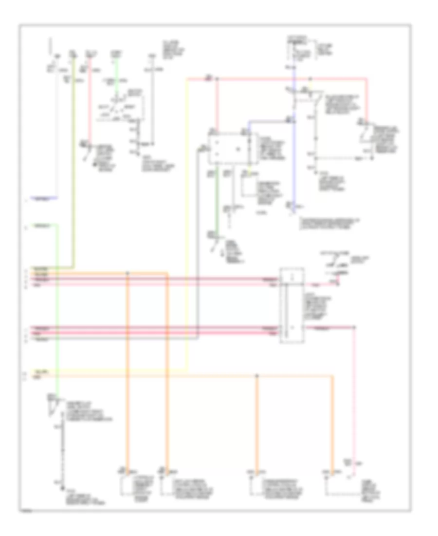
INSTRUMENT CLUSTER
Instrument Cluster Wiring Diagram, Analog (1 of 2) for Mercury Villager GS 1995
 https://portal-diagnostov.com/license.html
Automotive Electricians Portal FZCO
Automotive Electricians Portal FZCO
https://portal-diagnostov.com/license.html
https://portal-diagnostov.com/license.html
Automotive Electricians Portal FZCO
Automotive Electricians Portal FZCO
List of elements for Instrument Cluster Wiring Diagram, Analog (1 of 2) for Mercury Villager GS 1995:
- (behind top left side of i/p, right of
- (below center of i/p, on right side of center i/p support brace)
- (top left cowl panel, near door grommet)
- (top of right cowl panel, near door grommet)
- 10a
- 10b
- 10c
- 11b
- 11c
- 12b
- 12c
- 2 pole speed sensor
- Air bag diagnostic monitor (left rear of cargo area, above wheel well)
- Air bag ind.
- Anti- slosh module
- Anti-lock warning ind.
- Av02
- Av32
- Brake warning ind.
- Charge warning ind.
- Cluster)
- Conn a
- Conn b
- Conn c
- Connector #2
- Coolant temp.
- Coolant temp. gauge
- Coolant temperature sender (top right rear of engine)
- Cruise control module (below center of i/p, mounted on center i/p brace support)
- Cruise ind.
- Diode junction box (behind top left side of i/p, taped to main harness)
- Door ajar ind.
- Ej07
- Ej10
- Ej17
- Engine oil pressure switch (lower right front of engine, near oil filter)
- Engine speed
- Exterior lights system (hazard switch & combination switch)
- Fuel gauge
- Fuel gauge sender
- Fuel level
- Fuel pump module (below rear of vehicle, inside fuel tank)
- G200
- G201
- G203
- Gnd
- Headlights system (combination switch)
- Hi beam ind.
- Hot in run or start
- I/p fuse/ relay center
- Ign
- Illum. dim
- Illum. lamps
- Illum. power
- Instrument
- Instrument cluster
- Interior lights system
- Joint
- Left turn ind.
- Low fuel warning ind.
- Low oil level ind.
- Low oil press. ind.
- Low washer fluid ind.
- Malfunction ind.
- Meter fuse 21 10a
- Nca
- Nr01
- O/d off ind.
- Pnk
- Powertrain control module (behind top right side of i/p, behind glove box)
- Prndl illum. dim
- Prndl illum. lamp
- Prndl illum. pwr
- Ps03
- Red
- Red/ li98
- Right turn ind.
- Seat belt warning ind.
- Speedometer
- Tachometer
- Timer module (behind bottom of left cowl panel)
- Transaxle control module (behind top right side of i/p, behind glove box)
- V ref
- Vehicle speed in
- Vehicle speed out
- Vehicle speed sensor (left side of engine, on rear of transaxle)
- Zy03
- Zy24
- Zy27
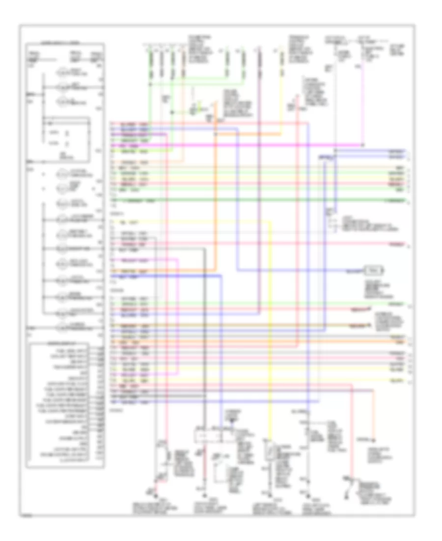
Instrument Cluster Wiring Diagram, Analog (2 of 2) for Mercury Villager GS 1995
 https://portal-diagnostov.com/license.html
Automotive Electricians Portal FZCO
Automotive Electricians Portal FZCO
https://portal-diagnostov.com/license.html
https://portal-diagnostov.com/license.html
Automotive Electricians Portal FZCO
Automotive Electricians Portal FZCOList of elements for Instrument Cluster Wiring Diagram, Analog (2 of 2) for Mercury Villager GS 1995:
- (below center of i/p, mounted on center i/p support brace)
- (left rear of engine compt, on brake fluid reservoir)
- (left rear of engine compt, on side of strut tower)
- (lower right front of engine compt, on washer fluid reservoir)
- (lower right front of engine)
- (on park brake assembly)
- (top of right cowl panel, near door grommet)
- Acc
- Anti-lock brake control module
- Brake fluid level switch
- Bulb check relay (left front of engine compt, in left engine compt relay block)
- Daytime running lamps module (right side of engine compt, on front of strut tower)
- Diode junction box (behind top left side of i/p, taped to main harness)
- Engine oil level switch
- G102
- G203
- Generator/ voltage regulator (lower right front of engine)
- Gnd
- Head
- Headlamp switch
- Hot at all times
- Hot in run or start
- Hydraulic actuator assembly (right front of engine compt)
- I/p fuse/ relay center
- Ig91
- Ign
- Ignition switch
- Ind. ctrl
- Joint connector #2 (behind top left side of i/p, right of instrument cluster)
- Lock
- Np02
- Np04
- Np05
- Off
- Oil level module (behind top right side of i/p)
- Oil lvl input
- Park
- Park brake switch
- Passive restraint control module
- Pnk
- Rly coil fuse 20 10a
- Run
- Start
- Start input
- Timer module (behind bottom of left cowl panel)
- W/ drl
- Washer fluid level switch
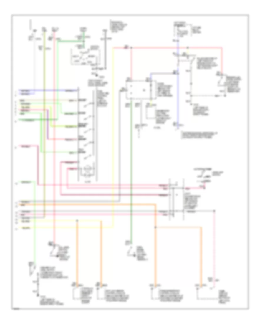
Instrument Cluster Wiring Diagram, Electronic (1 of 2) for Mercury Villager GS 1995
 https://portal-diagnostov.com/license.html
Automotive Electricians Portal FZCO
Automotive Electricians Portal FZCO
https://portal-diagnostov.com/license.html
https://portal-diagnostov.com/license.html
Automotive Electricians Portal FZCO
Automotive Electricians Portal FZCOList of elements for Instrument Cluster Wiring Diagram, Electronic (1 of 2) for Mercury Villager GS 1995:
- (below center of i/p, on right side of center i/p support brace)
- (left rear of engine compt, on side of strut tower)
- (top left cowl panel, near door grommet)
- (top of right cowl panel, near door grommet)
- 10a
- 10b
- 10c
- 11a
- 11b
- 11c
- 12a
- 12c
- 13a
- 13c
- 14a
- 14c
- 15c
- 16c
- 17c
- 18c
- 19c
- Air bag diagnostic monitor (left rear of cargo area, above wheel well)
- Air bag ind.
- Anti-lock warning ind.
- Av02
- Av05
- Av32
- Bat
- Brake warning ind.
- Bs29
- C20
- Charge warning ind.
- Conn a
- Conn b
- Conn c
- Coolant temp input
- Coolant temperature sender (top right rear of engine)
- Cruise control module (below center of i/p, mounted on center i/p brace support)
- Cruise control on input
- Data input-fuel flow
- Digital display
- Dimmer output
- Diode junction box (behind top left side of i/p, taped to main harness)
- Door ajar ind.
- Ej07
- Ej10
- Ej17
- Electron bat fuse 13 10a
- Engine oil pressure switch (lower right front of engine, near oil filter)
- Exterior lights system (hazard switch & combination switch)
- Fuel computer eng/met
- Fuel computer reset
- Fuel computer select
- Fuel computer trip/reset
- Fuel computer trip/select
- Fuel gauge sender
- Fuel level input
- Fuel pump module (below rear of vehicle, inside fuel tank)
- G102
- G200
- G201
- G203
- Gnd
- Grd
- Headlights system (combination switch)
- Hi beam ind.
- Hot at all times
- Hot in run or start
- I/p fuse/ relay center
- Ig01
- Ig91
- Ig92
- Ign
- Illum dim input
- Instrument cluster
- Interior lights system
- Joint connector #2 (behind top left side of i/p, right of instrument cluster)
- La03
- Lb15
- Lb16
- Left turn ind.
- Low fuel ind ctrl
- Low fuel warning ind.
- Low oil level ind.
- Low oil press. ind.
- Low washer fluid ind.
- Ma01
- Ma02
- Ma03
- Ma04
- Ma06
- Ma07
- Ma11
- Ma12
- Ma14
- Ma15
- Ma16
- Ma17
- Ma20
- Ma41
- Mae1
- Mae2
- Malfunction ind.
- Md01
- Meter fuse 21 10a
- Mj01
- Mje2
- Nb01
- Nca
- Nf01
- Ni03
- Nm01
- Nn01
- Np04
- Nr01
- O/d off ind.
- O/s temp sensor input
- Outside air temperature sensor (lower center front of vehicle, below front bumper)
- Pnk
- Powertrain control module (behind top right side of i/p, behind glove box)
- Prndl illum. dim
- Prndl illum. lamp
- Prndl illum. pwr
- Ps03
- Red
- Red/ li98
- Right turn ind.
- Seat belt warning ind.
- Start input
- Tachometer input
- Timer module (behind bottom of left cowl panel)
- Transaxle control module (behind top right side of i/p, behind glove box)
- Vehicle speed sensor (left side of engine, on rear of transaxle)
- Vss grd
- Vss input
- Vss ouput
- Zy03
- Zy24
- Zy27
Instrument Cluster Wiring Diagram, Electronic (2 of 2) for Mercury Villager GS 1995
 https://portal-diagnostov.com/license.html
Automotive Electricians Portal FZCO
Automotive Electricians Portal FZCO
https://portal-diagnostov.com/license.html
https://portal-diagnostov.com/license.html
Automotive Electricians Portal FZCO
Automotive Electricians Portal FZCOList of elements for Instrument Cluster Wiring Diagram, Electronic (2 of 2) for Mercury Villager GS 1995:
- (below center of i/p, mounted on center i/p support brace)
- (left rear of engine compt, on brake fluid reservoir)
- (left rear of engine compt, on side of strut tower)
- (lower right front of engine compt, on washer fluid reservoir)
- (lower right front of engine)
- (on park brake assembly)
- (top of right cowl panel, near door grommet)
- 0rg
- Acc
- Anti-lock brake control module
- Brake fluid level switch
- Bulb check relay (left front of engine compt, in left engine compt relay block)
- Daytime running lamps module (right side of engine compt, on front of strut tower)
- Diode junction box (behind top left side of i/p, taped to main harness)
- Engine oil level module (behind top right side of i/p)
- English/ metric
- Fuel computer control panel (left of steering column)
- G102
- G203
- Generator/ voltage regulator (lower right front of engine)
- Gnd
- Head
- Headlamp switch
- Hot at all times
- Hot in run or start
- Hydraulic actuator assembly (right front of engine compt)
- I/p fuse/ relay center
- Ig91
- Ign
- Ignition switch
- Illum.
- Ind. ctrl
- Joint connector #2 (behind top left side of i/p, right of instrument cluster)
- Lock
- Np02
- Np04
- Np05
- Off
- Oil level switch
- Oil lvl input
- Park
- Park brake switch
- Passive restraint control module
- Pnk
- Reset
- Rly coil fuse 20 10a
- Run
- Select
- Start
- Start input
- Timer module (behind bottom of left cowl panel)
- Trip reset
- Trip select
- W/ drl
- Washer fluid level switch

 Čeština
 Dansk
Dansk Deutsch
 Ελληνικά
 English
 English
 Español
 Suomi
Suomi Français
 Français
 עברית
עברית Hrvatski
 Magyar
 Italiano
 日本語
日本語 한국어
한국어 Nederlands
 Polski
 Português
 Português
 Română
 Русский
 Slovenčina
 Slovenščina
 Svenska
 Türkçe
