POWER DISTRIBUTION
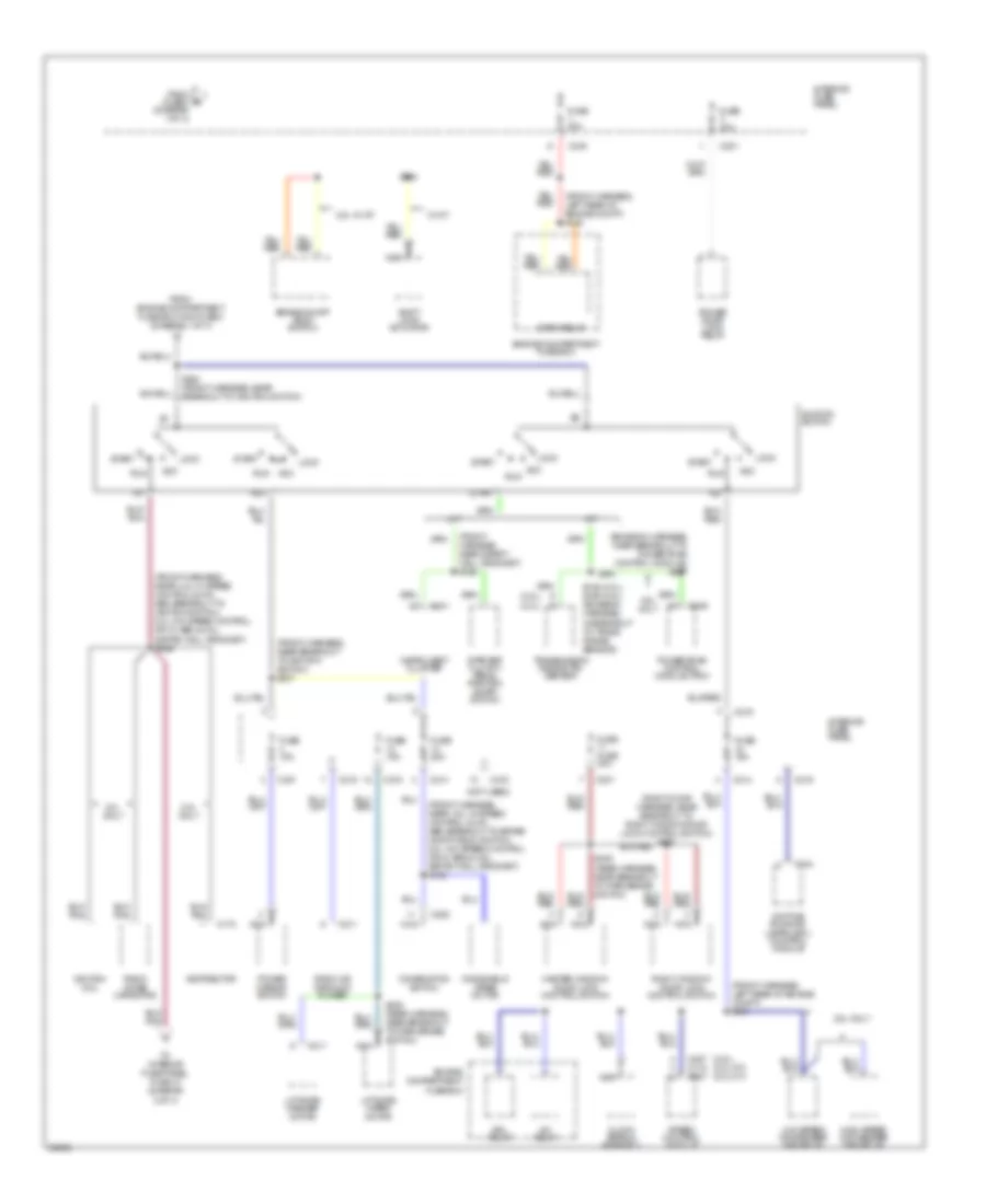
Power Distribution Wiring Diagram (1 of 3) for Ford Probe GT 1997
 https://portal-diagnostov.com/license.html
Automotive Electricians Portal FZCO
Automotive Electricians Portal FZCO
https://portal-diagnostov.com/license.html
https://portal-diagnostov.com/license.html
Automotive Electricians Portal FZCO
Automotive Electricians Portal FZCO
List of elements for Power Distribution Wiring Diagram (1 of 3) for Ford Probe GT 1997:
- (2.5l & 2.0l w/o speed control or w/ abs, front harness, in breakout to engine compt fuse box; 2.0l w/ speed control & w/o abs, front harness, near safety wall harness) s100
- (front harness, in breakout to engine compt fuse box) s102
- (i/p harness, near breakout to c206, left side of i/p)
- (i/p harness, near breakout to instrument cluster) s216
- (left side of i/p)
- (not used)
- (power seat switch harness) s310
- (rear harness, at left door sill) s222
- (rear harness, near breakout to sub- woofer amplifier) s306
- (rear harness, near breakout to c303, below right side of rear seat) s305
- 2.0l
- 2.5l
- 2.5l only
- A/c relay
- Abs main relay
- Air bag diagnostic monitor
- Battery
- C153
- C201
- C2020
- C204
- C207
- C209
- C211
- C213
- C214
- C215
- C216
- C217
- C240
- C248
- C315
- C318
- Central processing unit (cpu)
- Cigar lighter
- Combination switch
- Data link connector (dlc)
- Dome/ map lamp assembly
- Drl relay
- Engine compartment fuse box
- Flasher module
- Fog lamp relay
- Fuse 15a
- G202 (left side of i/p)
- Headlamp relay
- Headlamp retractor test connector
- High speed condenser fan relay
- High speed cooling fan relay
- Ignition key cylinder lamp
- Ignition key reminder switch
- Instrument cluster
- Integral generator/ regulator
- Interior fuse panel
- Joint connector c203
- Joint connector c234
- Left door key cylinder switch
- Left headlamp retractor
- Low speed blower motor relay
- Low speed condenser fan relay
- Luggage compartment lamp
- Master window/ door lock control switch
- Maxi fuse 1 30a
- Maxi fuse 10 40a
- Maxi fuse 11 15a
- Maxi fuse 12 20a
- Maxi fuse 13 30a
- Maxi fuse 2 40a
- Maxi fuse 3 30a
- Maxi fuse 4 100a
- Maxi fuse 5 40a
- Maxi fuse 6 60a
- Maxi fuse 7 60a
- Maxi fuse 8 40a
- Maxi fuse 9 40a
- Nca
- Park lamp relay
- Pcm power relay
- Power lumbar bolster switch
- Power seat switch
- Powertrain control module (pcm)
- Radio amplifier
- Radio or radio/ cd player
- Rear window defrost relay
- Red
- Remote entry module
- Right door key cylinder switch
- Right headlamp retractor
- Right window/ door lock control switch
- S130 (front harness, near breakout to left headlamp)
- S141 (front harness, in break- out to engine compt fuse box)
- S205
- S208
- S215
- S229 (front harn, in breakout to engine compt fuse box)
- S404 (rear harness, near breakout to left rear abs wheel speed sensor)
- Starter motor/ solenoid
- Subwoofer amplifier
- To fuse 1 (diagram 2 of 3)
- To splice s202 (diagram 2 of 3)
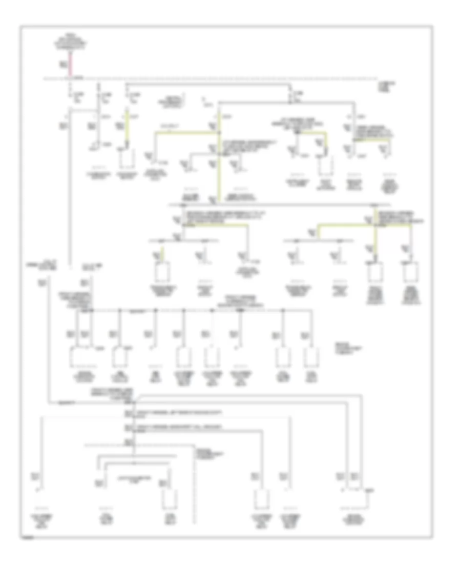
Power Distribution Wiring Diagram (2 of 3) for Ford Probe GT 1997
 https://portal-diagnostov.com/license.html
Automotive Electricians Portal FZCO
Automotive Electricians Portal FZCO
https://portal-diagnostov.com/license.html
https://portal-diagnostov.com/license.html
Automotive Electricians Portal FZCO
Automotive Electricians Portal FZCOList of elements for Power Distribution Wiring Diagram (2 of 3) for Ford Probe GT 1997:
- (2.5l) (2.0l a/t) (2.0l m/t)
- (2.5l) (2.0l)
- (emission harness, near breakout to powertrain control module) s257
- (front harness, left rear of engine compt) s148
- (front harness, left rear of engine compt) s151
- (front harness, near breakout to ignition switch) s237
- (front harness, near safety wall grommet) s156
- (front harness, near: 2.0l w/ speed control & w/o abs, breakout to brake on/off (boo) switch; 2.0l w/o speed control or w/ abs, & 2.5l, saftey wall grommet) s152
- (front harness, near: 2.0l w/ speed control & w/o abs, breakout to ignition switch; 2.0l w/o speed control or w/ abs, & 2.5l, saftey wall grommet) s236
- (not used)
- (right door harness, near breakout to right window/door lock control switch) s602
- 2.0l only
- 2.0l w/ a/t
- 2.5l 0nly
- 2.5l only
- A/c relay
- A/t
- Acc
- Brake on/off (boo) switch
- C170
- C201
- C211
- C214
- C215
- C216
- C225
- C227 c110 c227
- C241
- C244
- C246
- Clock spring assembly
- Combination switch
- Daytime running lamps (drl) control module
- Distributor
- Drl relay
- Engine compartment fuse box
- From engine compartment fuse box, maxi fuse 5 (diagram 1 of 3)
- From fuse 2 (diagram 1 of 3)
- Fuse 15a
- Fuse 20a
- Fuse 30a
- Fuse fuse 30a
- High speed condenser fan relay
- Horn relay
- Ig1
- Ig2
- Ignition coil
- Ignition switch
- Instrument cluster
- Interior fuse panel
- Liftgate washer motor
- Liftgate wiper motor
- Lock
- Low speed condenser fan relay
- M/t
- Master window/ door lock control switch
- Nca
- Power door lock relay
- Power mirror switch
- Powertrain control module (pcm)
- Radio noise capacitor
- Radio or radio/cd player
- Right window/ door lock control switch
- Run
- S146 (2.0l) s159 (2.5l) (emission harness, in breakout to trans range sensor)
- S202 (front harness, near breakout to ignition switch)
- S204
- S308 (rear harness, near breakout to park brake switch)
- S309 (rear harness, near breakout to park brake switch)
- Shift lock actuator
- Speed control module
- Start
- Starter clutch pedal position (scpp) switch
- To interior fuse panel, fuse 10 (diagram 3 of 3)
- Transmission range (tr) sensor
- W/ a/t
- Windshield wiper motor
Power Distribution Wiring Diagram (3 of 3) for Ford Probe GT 1997
 https://portal-diagnostov.com/license.html
Automotive Electricians Portal FZCO
Automotive Electricians Portal FZCO
https://portal-diagnostov.com/license.html
https://portal-diagnostov.com/license.html
Automotive Electricians Portal FZCO
Automotive Electricians Portal FZCOList of elements for Power Distribution Wiring Diagram (3 of 3) for Ford Probe GT 1997:
- (emission harness, near breakout to heated oxygen sensor) s164
- (emission harness, near breakout to: a/t, trans range sensor; m/t, ground g112, left side of engine) s150
- (front harness, in breakout to engine compt fuse box) s143
- (front harness, near breakout to interior fuse panel) s231
- (i/p harness, near breakout to ground g202, left side of i/p) s232
- (i/p harness, near breakout to ground g206, behind left center of i/p) s241
- (rear harness, near breakout to park brake switch) s311
- 2.0l
- 2.0l only
- 2.0l w/ abs or 2.5l
- 2.0l w/ speed control & w/o abs
- 2.5l
- A/t
- Abs control module
- Abs main relay
- Air bag diagnostic monitor
- Backup lamp switch
- Blower assembly
- C135
- C201
- C209
- C213
- C214
- C215
- C216
- C217
- C222
- C225
- C241
- C407
- Central processing unit (cpu)
- Combination switch
- Data link connector (dlc)
- Engine compartment fuse box
- From splice s236, hot in run/start (diagram 2 0f 3)
- Front heated oxygen sensor (ho2s) #11
- Fuel pump relay
- Fuse 15a
- High speed cooling fan relay
- Instrument cluster
- Interior fuse panel
- Joint connector c169
- Low speed blower motor relay
- Low speed cooling fan relay
- M/t
- Moonroof switch
- Nca
- Pcm power relay
- Rear heated oxygen sensor (ho2s) #12
- Rear window defrost relay
- Rear window defrost switch
- Remote entry module
- Shift lock actuator
- Transmission range (tr) sensor

 Čeština
 Dansk
Dansk Deutsch
 Ελληνικά
 English
 English
 Español
 Suomi
Suomi Français
 Français
 עברית
עברית Hrvatski
 Magyar
 Italiano
 日本語
日本語 한국어
한국어 Nederlands
 Polski
 Português
 Português
 Română
 Русский
 Slovenčina
 Slovenščina
 Svenska
 Türkçe
