POWER DISTRIBUTION
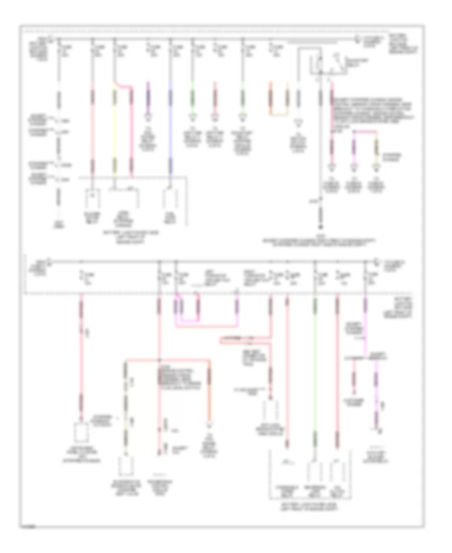
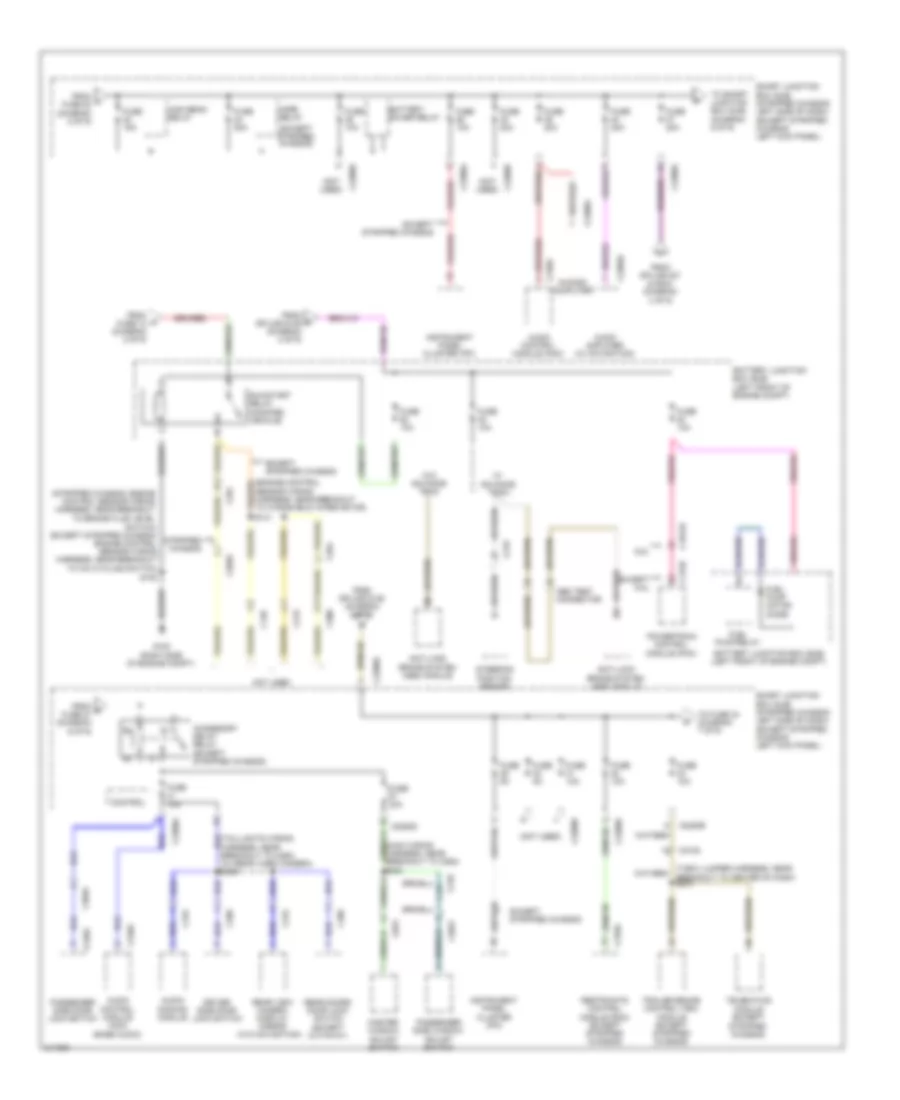
Power Distribution Wiring Diagram (1 of 9) for Ford RV Cutaway E350 Super Duty 2011
 https://portal-diagnostov.com/license.html
Automotive Electricians Portal FZCO
Automotive Electricians Portal FZCO
https://portal-diagnostov.com/license.html
https://portal-diagnostov.com/license.html
Automotive Electricians Portal FZCO
Automotive Electricians Portal FZCO
List of elements for Power Distribution Wiring Diagram (1 of 9) for Ford RV Cutaway E350 Super Duty 2011:
- (engine control red sensor wiring harness, in breakout to battery)
- (engine control sensor wiring harness, in breakout to battery)
- (engine control sensor wiring harness, near breakout to battery junction box (bjb))
- (left front of engine compt)
- (right front of engine compt)
- (right rear of engine)
- Battery
- Battery junction box (bjb)
- C102a
- C102b
- C1035a
- C1035b
- Except stripped chassis
- G109
- G120
- Generator
- Red
- S106
- S107
- S113
- S114
- S146
- S147
- S148
- S149
- S150
- Starter motor
- Stripped chassis
- To fuse 15 (diagram 2 of 9)
- To smart junction box (sjb) (diagram 3 of 9)
- W/ 125a generator
- W/ 150a or 215a generator
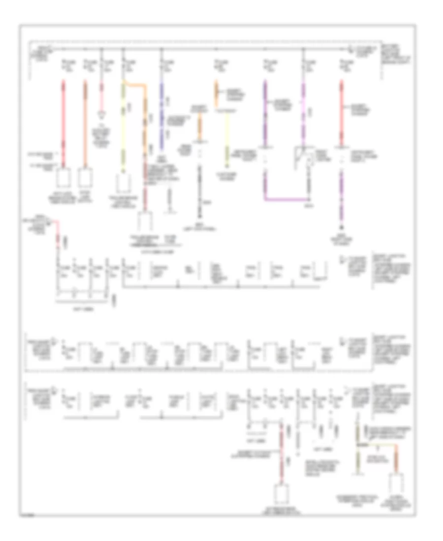
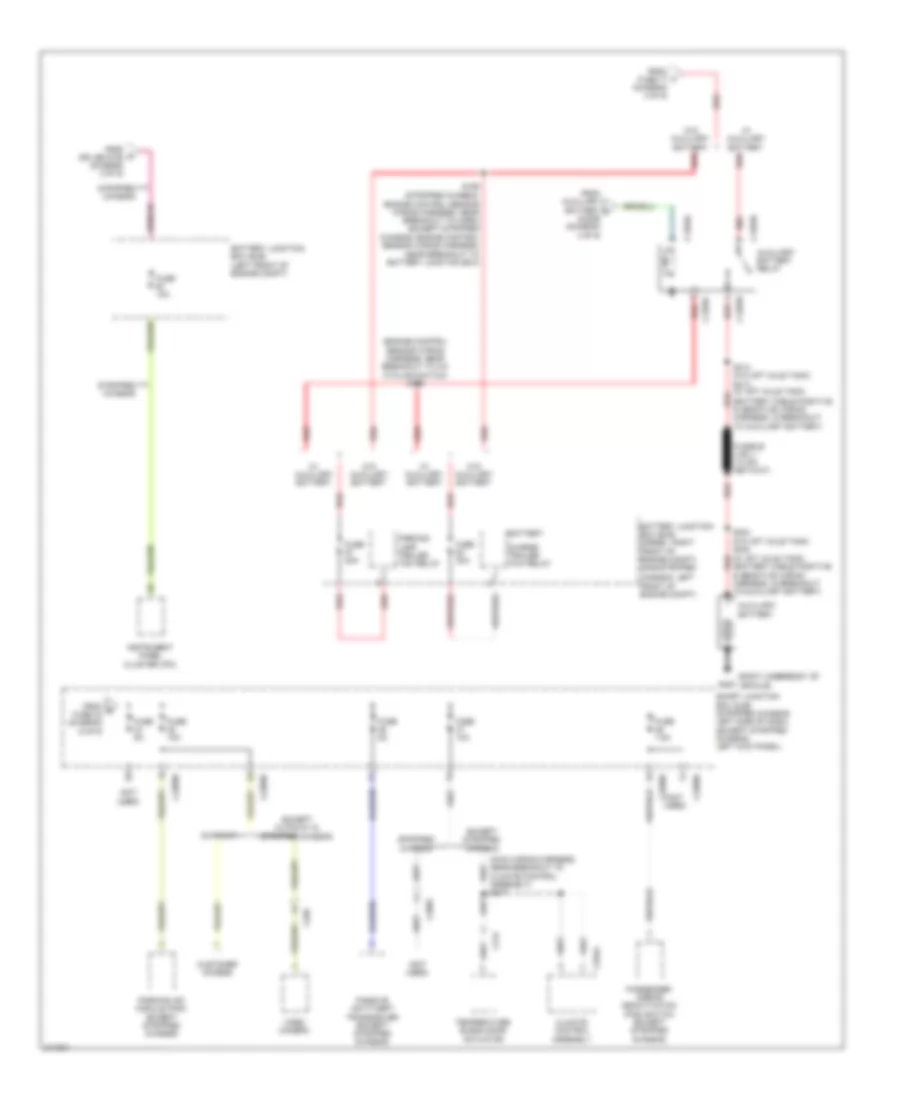
Power Distribution Wiring Diagram (2 of 9) for Ford RV Cutaway E350 Super Duty 2011
 https://portal-diagnostov.com/license.html
Automotive Electricians Portal FZCO
Automotive Electricians Portal FZCO
https://portal-diagnostov.com/license.html
https://portal-diagnostov.com/license.html
Automotive Electricians Portal FZCO
Automotive Electricians Portal FZCOList of elements for Power Distribution Wiring Diagram (2 of 9) for Ford RV Cutaway E350 Super Duty 2011:
- (except stripped chassis: engine
- (except stripped chassis: right front of engine compt) (stripped chassis: right side of engine compt)
- (left front of
- (left front of engine compt)
- (not used)
- 10a
- 30a
- 6.8l
- A/c clutch relay
- Abs test connector (w/ advance trac)
- Anti-lock brake system (abs) module
- Auxiliary blower motor relay
- Battery junction box (bjb)
- Battery junction box (bjb) (left front of engine compt)
- Blower motor relay
- Breakout to windshield wiper motor) (stripped chassis: engine control sensor wiring harness, near breakout to anti-lock brake system (abs)
- C110
- C1551b
- C175b
- C2026
- C264
- C291
- C300
- C405
- C408
- Chassis &
- Control sensor wiring harness, near
- Customer access
- Cutaway
- Engine compt)
- Evaporative emission (evap) canister vent valve
- Except
- Except 6.8l
- Except cutaway
- Except stripped chassis
- From a battery junction box (bjb) (diagram 1 of 9)
- From c fuse 41 (diagram 2 of 9)
- Fuel pump relay
- Fuse
- Fuse 10a
- Fuse 15a
- Fuse 20a
- Fuse 40a
- Fuse 50a
- G100
- Horn relay (stripped chassis)
- Instrument panel cluster (ipc) (stripped chassis)
- Left turn/stop trailer tow relay
- Module)
- Powertrain control module (pcm)
- Red
- Reversing lamp relay
- Right turn/stop trailer tow relay
- Run/start relay
- S108
- S129 (engine control sensor wiring harness, near breakout to brake fluid level switch)
- S136
- Stripped
- Stripped chassis
- To fuse 29 (diagram 6 of 9)
- To fuse 31 (diagram 2 of 9)
- To fuse 33 (diagram 3 of 9)
- To fuse 52 (diagram 6 of 9)
- To fuse 80 (diagram 7 of 9)
- To ignition switch (diagram 4 of 9)
- To pcm power relay (diagram 8 of 9)
- To run/start relay (modified vehicle) (diagram 6 of 9)
- To upfitter relay 3 (diagram 9 of 9)
- To upfitter relay 4 (diagram 9 of 9)
- W/ advance trac
- Windshield wiper relay
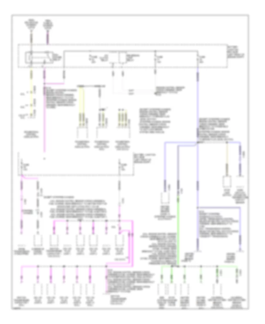
Power Distribution Wiring Diagram (3 of 9) for Ford RV Cutaway E350 Super Duty 2011
 https://portal-diagnostov.com/license.html
Automotive Electricians Portal FZCO
Automotive Electricians Portal FZCO
https://portal-diagnostov.com/license.html
https://portal-diagnostov.com/license.html
Automotive Electricians Portal FZCO
Automotive Electricians Portal FZCOList of elements for Power Distribution Wiring Diagram (3 of 9) for Ford RV Cutaway E350 Super Duty 2011:
- & stripped chassis
- (apim)
- (gpsm)
- (main wiring harness, near breakout to left side of dash)
- (not used)
- (stripped chassis: left side of dash) (except stripped chassis: left kick panel)
- (t-box jumper harness , near breakout to center of dash)
- 3rd row seat enable (fet)
- Accessory protocol
- Anti-lock brake system (abs) module
- Back lighting led (fet)
- Battery junction box (bjb) (left front of engine compt)
- Bsi (fet)
- C110
- C2108
- C219
- C2280a
- C2280b
- C2280d
- C2280g
- C268
- C432
- Customer access
- Cutaway
- Cutaway &
- Except cutaway
- Except stripped chassis
- Exterior rear view mirror switch
- Floor lamp (fet)
- From d fuse 16 (diagram 2 of 9)
- From smart f junction box (sjb) (diagram 3 of 9)
- From smart g junction box (sjb) (diagram 3 of 9)
- From splice s114 & s153 (diagram 1 of 9)
- Front cigar lighter
- Fuse 10a
- Fuse 15a
- Fuse 20a
- Fuse 30a
- Fuse 40a
- Fuse 50a
- Fuse 5a
- Fuse 7.5a
- G200 (right side of dash)
- G203 (left kick panel)
- Global
- Inline fuse
- Instrument panel power point 1
- Instrument panel power point 2
- Interface module
- Interior lighting (fet)
- Keypad illmu (fet)
- Left low beam (fet)
- Lf turn lamp (fet)
- Lr stop/ turn lamp (fet)
- Lr turn lamp (fet)
- Not used
- Positioning
- Puddle lamp (fet)
- Rear power point
- Red
- Rf turn lamp (fet)
- Right low beam (fet)
- Rr stop/ turn lamp (fet)
- Rr turn lamp (fet)
- S218
- S240
- S268
- S272
- Satellite digital audio receiver system (sdars) module
- Smart junction box (sjb)
- Stop- lamp switch
- Stripped chassis
- Sync w/o navigation
- System module
- To auxiliary battery relay (diagram 7 of 9)
- To fuse 42 (diagram 4 of 9)
- To smart junction box (sjb) (diagram 3 of 9)
- To smart junction box (sjb) (diagram 5 of 9)
- Tpms (fet)
- Trailer brake control (tbc) module
- Vbatt
- W/ advance trac
- W/o advance trac
- White light (fet)
- With crew chief
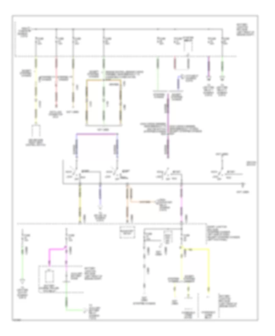
Power Distribution Wiring Diagram (4 of 9) for Ford RV Cutaway E350 Super Duty 2011
 https://portal-diagnostov.com/license.html
Automotive Electricians Portal FZCO
Automotive Electricians Portal FZCO
https://portal-diagnostov.com/license.html
https://portal-diagnostov.com/license.html
Automotive Electricians Portal FZCO
Automotive Electricians Portal FZCOList of elements for Power Distribution Wiring Diagram (4 of 9) for Ford RV Cutaway E350 Super Duty 2011:
- (engine control sensor wiring harness, near breakout to windshield wiper motor) s143
- (main wiring harness, near breakout to g202) (except stripped chassis) s227
- (main wiring harness, near breakout to ignition switch) (stripped chassis) s244
- (not used)
- (stripped chassis)
- Acc
- Auxiliary battery diode
- Battery charge trailer tow relay
- Battery junction box (bjb) (left front of engine compt)
- C140
- C2095
- C215
- C2280a
- C2280b
- C2280d
- C2280e
- C264
- C269
- C291
- C300
- C3133
- Data link connector (dlc)
- Driver side front seat control switch
- Except stripped chassis
- From e fuse 65 (diagram 3 of 9)
- From run/start relay (diagram 2 of 9)
- Fuse 10a
- Fuse 15a
- Fuse 20a
- Fuse 30a
- Fuse 50a
- Fuse 5a
- Ignition switch
- Lock
- Not used
- Off
- Run
- Run/ acc ign sw
- Run/start ign sw
- Smart junction box (sjb) (stripped chassis: left side of dash) (except stripped chassis: left kick panel)
- Start
- Starter relay
- Stripped chassis
- To auxiliary battery relay (diagram 7 of 9)
- To fuse 27 (diagram 6 of 9)
- To splice 132 (diagram 5 of 9)
- To upfitter relay 1 (diagram 9 of 9)
- To upfitter relay 2 (diagram 9 of 9)
- To upfitter switch (diagram 9 of 9)
- Windshield wiper motor
- Windshield wiper relay
Power Distribution Wiring Diagram (5 of 9) for Ford RV Cutaway E350 Super Duty 2011
 https://portal-diagnostov.com/license.html
Automotive Electricians Portal FZCO
Automotive Electricians Portal FZCO
https://portal-diagnostov.com/license.html
https://portal-diagnostov.com/license.html
Automotive Electricians Portal FZCO
Automotive Electricians Portal FZCOList of elements for Power Distribution Wiring Diagram (5 of 9) for Ford RV Cutaway E350 Super Duty 2011:
- (abs) module)
- (except stripped chassis: engine control sensor wiring harness, near breakout to windshield wiper motor) (stripped chassis: engine control sensor wiring harness, near breakout to anti-lock brake system
- (except stripped chassis: engine control sensor wiring harness, near breakout to windshield wiper motor) (stripped chassis: engine control sensor wiring harness, near breakout to anti-lock brake system (abs) module) s139
- (not used)
- (stripped chassis: left side of dash) (except stripped chassis: left kick panel)
- 6.8l
- Audio control module (acm) (except stripped chassis)
- Battery junction box (bjb) (left front of engine compt)
- C1551b
- C175b
- C192
- C219
- C2280a
- C2280b
- C2280d
- C2408a
- C240a
- Data link connector (dlc)
- Digital transmission range (dtr) sensor (4 speed a/t)
- Door lock relay
- Driver door unlock relay
- Except 6.8l
- Except stripped chassis
- Fog lamp relay
- From h fuse 14 (diagram 3 of 9)
- From ignition switch l (diagram 4 of 9)
- Fuse 15a
- Fuse 20a
- Fuse 25a
- Fuse 5a
- In-dash computer (except stripped chassis)
- Lh corner lamp (fet)
- Liftgate glass release relay
- Liftgate rel (fet)
- Park lamp relay
- Powertrain control module (pcm)
- Pulse train (fet)
- Rh corner lamp (fet)
- S132 (engine control sensor wiring harness, near breakout to brake fluid level switch)
- S139
- Smart junction box (sjb)
- Start diode
- Starter relay
- Stripped chassis
- To smart junction box (sjb) (diagram 6 of 9)
- W/ torqshift
Power Distribution Wiring Diagram (6 of 9) for Ford RV Cutaway E350 Super Duty 2011
 https://portal-diagnostov.com/license.html
Automotive Electricians Portal FZCO
Automotive Electricians Portal FZCO
https://portal-diagnostov.com/license.html
https://portal-diagnostov.com/license.html
Automotive Electricians Portal FZCO
Automotive Electricians Portal FZCOList of elements for Power Distribution Wiring Diagram (6 of 9) for Ford RV Cutaway E350 Super Duty 2011:
- (engine control sensor wiring harness, near breakout to windshield wiper motor)
- (except stripped chassis)
- (main wiring harness, near breakout to c264) s234
- (not used)
- (stripped chassis: engine control sensor wiring harness, near breakout to brake fluid level
- (t-box jumper harness, near breakout to center of dash) s274
- 6.8l
- Abs test connector
- Accessory delay relay (except stripped chassis)
- Anti-lock brake system (abs) module
- Audio amplifier (w/ navigation)
- Audio control module (acm)
- Audio control module (acm) (base audio)
- Audio- dimming module
- Battery junction box (bjb) (left front of engine compt)
- Battery saver relay
- C140
- C1551b
- C175b
- C2026
- C210
- C2108
- C215
- C219
- C2280a
- C2280b
- C2280d
- C2280e
- C2385b
- C2408a
- C240a
- C264
- C265
- C268
- C291
- C300
- C3047
- C3049
- C310a
- C315
- C406
- Control
- Driver side door lock switch
- Except 6.8l
- Except stripped chassis
- From fuse 27 (diagram 6 of 9)
- From j fuse 22 (diagram 5 of 9)
- From n fuse 12 (diagram 2 of 9)
- From r splice s136 (diagram 2 of 9)
- From splice 227 & s244 (diagram 4 of 9)
- From splice s136 (diagram 2 of 9)
- Fuel pump motor diode
- Fuel pump relay
- Fuse 10a
- Fuse 15a
- Fuse 20a
- Fuse 30a
- Fuse 5a
- G100 (right side of engine compt)
- High beam relay
- Horn relay
- In-dash computer
- Instrument panel cluster (ipc)
- Master window adjust switch
- Not used
- Passenger side door lock switch
- Passenger side window adjust switch
- Powertrain control module (pcm)
- Rear doors door lock switch (except cutaway)
- Rear view camera display mirror (w/o navigation)
- Restraints control module (rcm) (except stripped chassis)
- Run/start relay (modified vehicle)
- S108
- Smart junction box (sjb) (stripped chassis: left side of dash) (except stripped chassis: left kick panel)
- Steering position sensor
- Stripped chassis
- Switch) (except stripped chassis: engine control sensor wiring harness, near breakout to a/c cycling switch)
- Telematics module (except stripped chassis)
- To fuse 34 (diagram 7 of 9)
- To smart junction box (sjb) (diagram 6 of 9)
- Trailer brake control (tbc) module (except stripped chassis)
- W/ advance trac
- W/o advance trac
Power Distribution Wiring Diagram (7 of 9) for Ford RV Cutaway E350 Super Duty 2011
 https://portal-diagnostov.com/license.html
Automotive Electricians Portal FZCO
Automotive Electricians Portal FZCO
https://portal-diagnostov.com/license.html
https://portal-diagnostov.com/license.html
Automotive Electricians Portal FZCO
Automotive Electricians Portal FZCOList of elements for Power Distribution Wiring Diagram (7 of 9) for Ford RV Cutaway E350 Super Duty 2011:
- (engine control sensor wiring harness, near breakout to a/c cycling switch) s109
- (main wiring harness, near breakout to climate control assembly) s217
- (not used)
- (right underbody of g300 vehicle)
- Auxiliary battery
- Auxiliary battery relay
- Battery
- Battery junction box (bjb) (diesel: right front of engine compt) (gas/stripped
- Battery junction box (bjb) (left front of engine compt)
- C1283a
- C1283b
- C1283c
- C1283d
- C2095
- C214
- C2280b
- C2280d
- C294a
- C406
- Charge trailer tow relay
- Chassis: left
- Climate control assembly
- Customer access
- Cutaway
- Except cutaway & stripped chassis
- Except stripped chassis
- From auxiliary battery v diode (diagram 4 of 9)
- From q fuse 33 (diagram 6 of 9)
- From s splice s136 (diagram 2 of 9)
- From u fuse 17 (diagram 3 of 9)
- Front of engine compt)
- Fuse 10a
- Fuse 20a
- Fuse 30a
- Fuse 5a
- Fuse 7.5a
- Instrument panel cluster (ipc)
- Parking aid module (pam) (except stripped chassis)
- Parking lamp trailer tow relay
- Passenger airbag deactivation (pad) switch (except stripped chassis)
- Passive anti-theft transceiver (except stripped chassis)
- Red
- S159 (stripped chassis: engine control sensor wiring harness, near breakout to horn) (except stripped chassis: engine control sensor wiring harness, near breakout to battery junction box)
- S303
- S313 (w/o aft axle tank) s413 (w/ aft axle tank)
- Smart junction box (sjb) (stripped chassis: left side of dash) (except stripped chassis: left kick panel)
- Stripped chassis
- Temperature blend door actuator
- Video camera
- W/ auxiliary battery
- W/o auxiliary battery
Power Distribution Wiring Diagram (8 of 9) for Ford RV Cutaway E350 Super Duty 2011
 https://portal-diagnostov.com/license.html
Automotive Electricians Portal FZCO
Automotive Electricians Portal FZCO
https://portal-diagnostov.com/license.html
https://portal-diagnostov.com/license.html
Automotive Electricians Portal FZCO
Automotive Electricians Portal FZCOList of elements for Power Distribution Wiring Diagram (8 of 9) for Ford RV Cutaway E350 Super Duty 2011:
- control sensor wiring
- (4.6l: engine control sensor wiring harness &
- (5.4l: engine control sensor wiring harness & fuel charge, near breakout to fuel injector 2)
- (6.8l)
- (6.8l: engine control sensor wiring harness & fuel charge, near breakout to coil on plug (cop) 10) (5.4l: engine control sensor wiring harness & fuel charge, near breakout to fuel injector 8) (4.6l: engine control sensor wiring harness & fuel charge, near breakout to manifold absolute pressure (map) sensor) s174
- (6.8l: engine control sensor wiring harness & fuel charge, near breakout to fuel injector 1)
- (engine control sensor wiring harness, near breakout to c134) s124
- (except stripped chassis: engine control sensor wiring harness, near breakout to brake fluid level switch)
- (except stripped chassis: engine control sensor wiring harness, near breakout to windshield wiper motor)
- (ho2s) 11
- (ho2s) 11 (4.6l & 5.4l)
- (ho2s) 12
- (ho2s) 12 (stripped chassis & cutaway)
- (ho2s) 21 (4.6l & 5.4l)
- (ho2s) 22
- (stripped chassis: engine
- 4.6l & 5.4l
- 4r75e transmission (if equipped)
- 6.0l
- 6.8l
- A/c clutch relay
- Battery junction box (bjb) (left front of engine compt)
- C1033
- C134
- C1381b
- C1551b
- C1571
- C1572
- C175b
- C192
- C192) (6.8l: transmission control selector neutral switch wiring harness, near breakout to torqshift transmission)
- C219
- C314
- C4354
- Coil on plug (cop) 1
- Coil on plug (cop) 10 (6.8l)
- Coil on plug (cop) 2
- Coil on plug (cop) 3
- Coil on plug (cop) 4
- Coil on plug (cop) 5
- Coil on plug (cop) 6
- Coil on plug (cop) 7
- Coil on plug (cop) 8
- Coil on plug (cop) 9 (6.8l)
- Crankcase ventilation (pcv) valve)
- Diesel
- Egr system module (esm) (4.6l)
- Evap canister purge valve
- Except stripped chassis
- From fuse 35 (diagram 2 of 9)
- From splice s129 (diagram 2 of 9)
- Fuel charge, near breakout to heated positive
- Fuse 10a
- Fuse 15a
- Fuse 20a
- Gasoline
- Harness & fuel charge, near breakout to coil on plug (cop) 7) (6.8l: engine control sensor wiring harness & fuel charge, near breakout to c1046)
- Harness, near breakout to anti-lock brake system (abs) module)
- Heated oxygen sensor
- Heated oxygen sensor (ho2s) 21
- Ignition transformer capacitor 1 (4.6l & 5.4l)
- Ignition transformer capacitor 1 (6.8l)
- Ignition transformer capacitor 2 (4.6l & 5.4l)
- Mass air flow intake air temperature (maf/iat) sensor
- Overdrive cancel switch
- Pcm power relay
- Powertrain control module (pcm)
- Powertrain control module (pcm) (4.6l & 5.4l)
- Powertrain control module (pcm) (6.8l)
- Reversing lamp relay
- S103 (except stripped chassis & cutaway) (4r75e: transmission control selector neutral switch wiring harness, near breakout to
- S131
- S137
- S170 (4.6l: engine control sensor wiring harness & fuel charge, near breakout to powertrain control module (pcm) )
- S177
- Stop lamp switch
- Stripped chassis
- Universal heated oxygen sensor
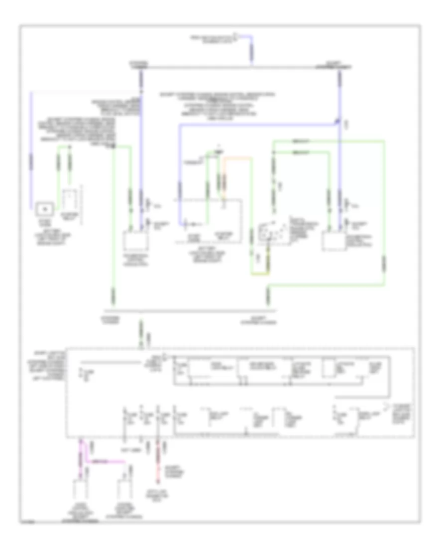
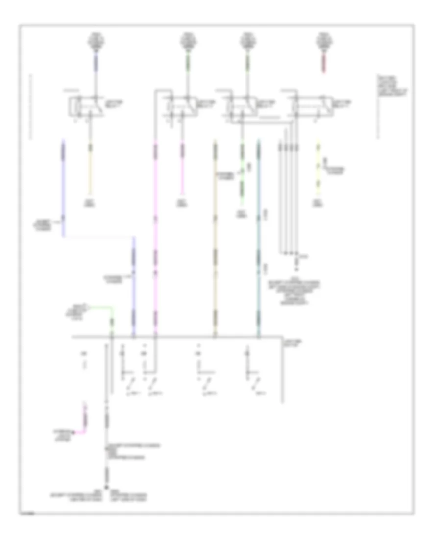
Power Distribution Wiring Diagram (9 of 9) for Ford RV Cutaway E350 Super Duty 2011
 https://portal-diagnostov.com/license.html
Automotive Electricians Portal FZCO
Automotive Electricians Portal FZCO
https://portal-diagnostov.com/license.html
https://portal-diagnostov.com/license.html
Automotive Electricians Portal FZCO
Automotive Electricians Portal FZCOList of elements for Power Distribution Wiring Diagram (9 of 9) for Ford RV Cutaway E350 Super Duty 2011:
- (center of dash)
- (except stripped chassis) s264 s250 (stripped chassis)
- (left side of dash)
- (not used)
- Battery junction box (bjb) (left front of engine compt)
- C175b
- C298
- Except stripped chassis
- From fuse 19 (diagram 4 of 9)
- From fuse 20 (diagram 4 of 9)
- From fuse 44 (diagram 2 of 9)
- From fuse 45 (diagram 2 of 9)
- From i fuse 42 (diagram 4 of 9)
- G101 (except stripped chassis:
- G201 (except stripped chassis)
- G205 (stripped chassis)
- Interior lights system
- Left side of engine compt) (stripped chassis: left front corner of engine compt)
- S123
- Stripped chassis
- Sw 1
- Sw 2
- Sw 3
- Sw 4
- Upfitter relay 1
- Upfitter relay 2
- Upfitter relay 3
- Upfitter relay 4
- Upfitter switch

 Čeština
 Dansk
Dansk Deutsch
 Ελληνικά
 English
 English
 Español
 Suomi
Suomi Français
 Français
 עברית
עברית Hrvatski
 Magyar
 Italiano
 日本語
日本語 한국어
한국어 Nederlands
 Polski
 Português
 Português
 Română
 Русский
 Slovenčina
 Slovenščina
 Svenska
 Türkçe
