TRANSMISSION
6.8L
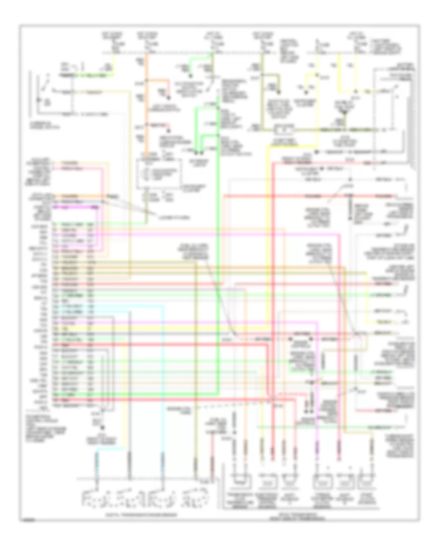
6.8L, A/T Wiring Diagram, 4R100 for Ford E450 Super Duty 2002
 https://portal-diagnostov.com/license.html
Automotive Electricians Portal FZCO
Automotive Electricians Portal FZCO
https://portal-diagnostov.com/license.html
https://portal-diagnostov.com/license.html
Automotive Electricians Portal FZCO
Automotive Electricians Portal FZCO
List of elements for 6.8L, A/T Wiring Diagram, 4R100 for Ford E450 Super Duty 2002:
- (eng control harn, near breakout to a/c cutout switch)
- (eng control harn, near breakout to a/c pressure cutout switch)
- (eng ctrl harn, near breakout to pcm)
- (engine control harn, above left bank of engine)
- (engine ctrl harn)
- (in battery junction box)
- (top center of engine compt) mass airflow (maf) sensor
- (trans ctrl harn, near breakout to dtr sensor)
- (trans ctrl harn, near trans) s102
- 4r100 transmission
- Abs system, warning buzzer module
- Battery junction box
- Battery junction box (left front of engine compt)
- Bpp
- Brake pedal position switch (on bracket, above brake pedal)
- C220a
- C220b
- C220c
- C224
- C225
- C226
- Cc sol
- Central junction box (behind left side of dash)
- Cht
- Coast clutch solenoid
- Cruise control system
- Cylinder head temperature sensor (top front of left cylinder head)
- Data (+)
- Data (-)
- Data link connector (below left side of dash)
- Digital transmission range sensor
- Electronic pressure control solenoid
- Eng compt)
- Engine controls
- Epc
- Exterior lights
- Fuse 10a
- Fuse 15a
- Fuse 30a
- Fuse 5a
- G101 (front of right front fender)
- G203 (behind upper left side of dash)
- Gen data
- Gnd
- Hot at all times
- Hot in run or start
- Iat
- Instrument cluster
- Instrument cluster system
- Instrumentation engine coolant temperature sensor (upper left front of engine)
- Kapwr
- Maf
- Malfunction indicator lamp
- Mil
- Multifunction switch, deactivator switch
- Nca
- Od off
- Oss
- Output shaft speed sensor (left side of transmission)
- Overdrive cancel switch
- Pcm diode
- Pcm power relay
- Powertrain control module (pcm) (left rear of engine compartment, near brake master cylinder)
- Pwr in
- Radio noise capacitors, ignition coils
- Red
- S100
- S110
- S127
- S134 (eng ctrl harn, near a/c press cutout sw)
- S135 (eng cntrl harn, near a/c press cutout switch)
- S136
- S137
- S138
- S140
- S142
- S157
- S175
- S213
- Shift solenoid a
- Shift solenoid b
- Sig rtn
- Speedometer
- Ssa
- Tcc
- Tcil
- Tcs
- Tft
- Throttle position sensor (tps) (on top of engine, near air intake)
- Torque converter clutch solenoid
- Tps
- Tr1
- Tr2
- Tr3
- Tr4
- Transmission fluid temperature sensor
- Tss
- Turbine shaft speed sensor (left side of transmission)
- Vref
- Vss
- Vss gnd
7.3L DI TURBO DIESEL
7.3L DI Turbo Diesel, A/T Wiring Diagram, 4R100 for Ford E450 Super Duty 2002
 https://portal-diagnostov.com/license.html
Automotive Electricians Portal FZCO
Automotive Electricians Portal FZCO
https://portal-diagnostov.com/license.html
https://portal-diagnostov.com/license.html
Automotive Electricians Portal FZCO
Automotive Electricians Portal FZCOList of elements for 7.3L DI Turbo Diesel, A/T Wiring Diagram, 4R100 for Ford E450 Super Duty 2002:
- (behind upper left side of dash) g203
- (center left side of engine) engine oil temperature sensor
- (engine control harness, near breakout to pcm)
- (engine ctrl harn)
- (engine ctrl harn, near breakout to a/c press cutout sw)
- (fuel inj harn, near breakout to engine oil temp sensor)
- (fuel inj harn, near fuel injectors)
- (in battery junction box)
- (lower i/p harn)
- 4r100 transmission (right side of transmission)
- Abs system, warning buzzer module
- Accelerator pedal (ap) position sensor (behind left side of dash, above accelerator pedal)
- Acel pdl
- Ap sens
- Auxiliary powertrain control connector (partial) (behind left side of dash)
- Battery junction box
- Battery junction box (left front of engine compt)
- Bpp
- Brake pedal position switch (on bracket, above brake pedal)
- C220b
- C220c
- C225
- C226
- Ccs
- Central junction box (behind left side of dash)
- Chk eng
- Coast clutch solenoid
- Data (+)
- Data (-)
- Data link connector (dlc) (partial) (below left side of dash)
- Digital transmission range sensor
- Electronic pressure control solenoid
- Eng compt)
- Eng oil
- Engine controls
- Epc
- Exterior lights
- Fuse 10a
- Fuse 15a
- Fuse 30a
- Fuse 5a
- G101 (front of right front fender)
- Gen data
- Glow plug relay, fuel line htr, idle validation switch
- Gnd
- Hot at all times
- Hot in run or start
- Iat
- Idm relay, fuel pump relay
- Instrument cluster
- Intake air temperature sensor (center of engine compt, part of clean air tube)
- Kapwr
- Low vacuum warning switch
- Malfunction indicator lamp
- Manifold absolute pressure sensor (right side of engine compt)
- Map
- Multifunction switch deactivator switch
- Nca
- Od off
- Overdrive cancel switch
- Pcm diode
- Pcm power relay
- Powertrain control module (pcm) (left rear of engine compartment, near brake master cylinder)
- Pwr in
- Red
- S1001
- S1007
- S110
- S127
- S134 (eng ctrl harn, near a/c press cutout switch)
- S135
- S136
- S137
- S138
- S139
- S140
- S142
- S146
- S175
- S176 (w/ electric fuel pump)
- S213
- S262
- S263
- Shift solenoid a
- Shift solenoid b
- Sig rtn
- Ssa
- Ssb
- Tcc
- Tcil
- Tcs
- Tft
- Torque converter clutch solenoid
- Tr1
- Tr2
- Tr3
- Tr4
- Transmission fluid temperature sensor
- Tss
- Turbine shaft speed sensor (w/ electric fuel pump) (right side of transmission)
- Vehicle speed sensor (left side of transmission)
- Vref
- Vss
- Vss gnd

 Čeština
 Dansk
Dansk Deutsch
 Ελληνικά
 English
 English
 Español
 Suomi
Suomi Français
 Français
 עברית
עברית Hrvatski
 Magyar
 Italiano
 日本語
日本語 한국어
한국어 Nederlands
 Polski
 Português
 Português
 Română
 Русский
 Slovenčina
 Slovenščina
 Svenska
 Türkçe
