ENGINE PERFORMANCE
1.8L VIN 8
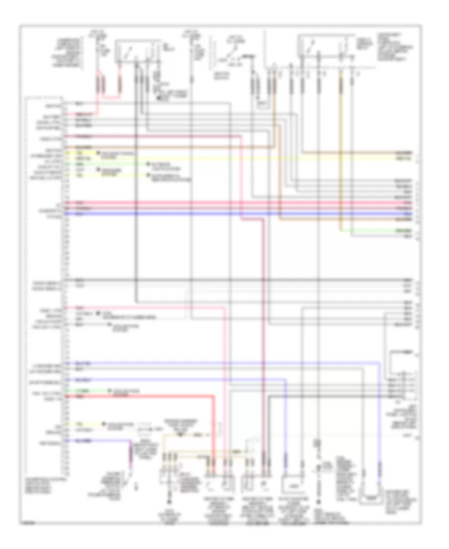
1.8L VIN 8, Engine Performance Wiring Diagram, AWD (1 of 3) for Pontiac Vibe GT 2006
 https://portal-diagnostov.com/license.html
Automotive Electricians Portal FZCO
Automotive Electricians Portal FZCO
https://portal-diagnostov.com/license.html
https://portal-diagnostov.com/license.html
Automotive Electricians Portal FZCO
Automotive Electricians Portal FZCO
List of elements for 1.8L VIN 8, Engine Performance Wiring Diagram, AWD (1 of 3) for Pontiac Vibe GT 2006:
- (at left front strut tower) g103
- (left of steering column, behind storage compt) instrument panel fuse block
- (left rear of vehicle, behind upper trim panel)
- (left side of cylinder head) g104
- (near noise filter) s104
- (on left side of cylinder head)
- 5v ref
- Acc
- Accelerator pedal position (app) sensor (bottom left of dash, on accelerator bracket)
- App sen 1 sig
- App sen 2 sig
- Battery
- C11
- C12
- Camshaft position sensor (left rear of engine, on
- Circuit opening relay
- Ckp sen in
- Cooling fans system
- Crankshaft position (ckp) sensor (bottom front of engine, near crankshaft pulley)
- Cylinder head)
- Data link
- Defogger system
- Diagnostic
- Efi fuse 15a
- Efi relay
- Evap purge
- Exterior lights system
- Fan 1 rly ctrl
- Ftp sens in
- Fuel pump
- Fuel sender assembly (under rear seat cushion)
- G105
- G201
- G300
- Ground
- Heated oxygen sensor 1 (rear of engine compt, in exhaust manifold)
- Heated oxygen sensor 2 (in exhaust, after 3-way catalytic converter)
- High pc sol
- High ref
- Ho2s 1 in
- Ho2s 2 in
- Hot at all times
- Idle-up defog
- Idle-up tail
- Ign voltage
- Ignition
- Ignition switch
- Input shaft speed sensor
- Knock sig hi
- Knock sig lo
- Left instrument panel junction block (behind left side of dash)
- Lock
- Low pc sol
- Low ref
- Mil ctrl
- Nca
- Pnk
- Power steering pressure switch (top of power steering pump)
- Powertrain control module (pcm) (behind right side of dash)
- Pressure sig
- Red
- S103
- S110
- S125
- S203
- S237
- Shift sol ctrl
- Sir fuel cutoff
- Sp107 (in engine accessory harness, near pcm)
- Sp201 (behind right body hinge pillar trim panel)
- Ss 1 ctrl
- Start
- Tcc ctrl
- Underhood fuse block (left side of engine compt, mounted to inner fender)
- Vacuum pump
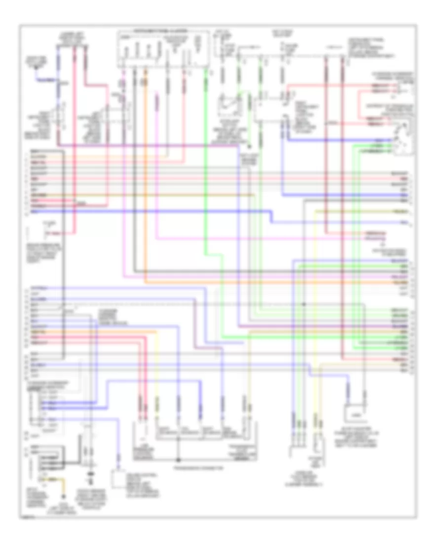
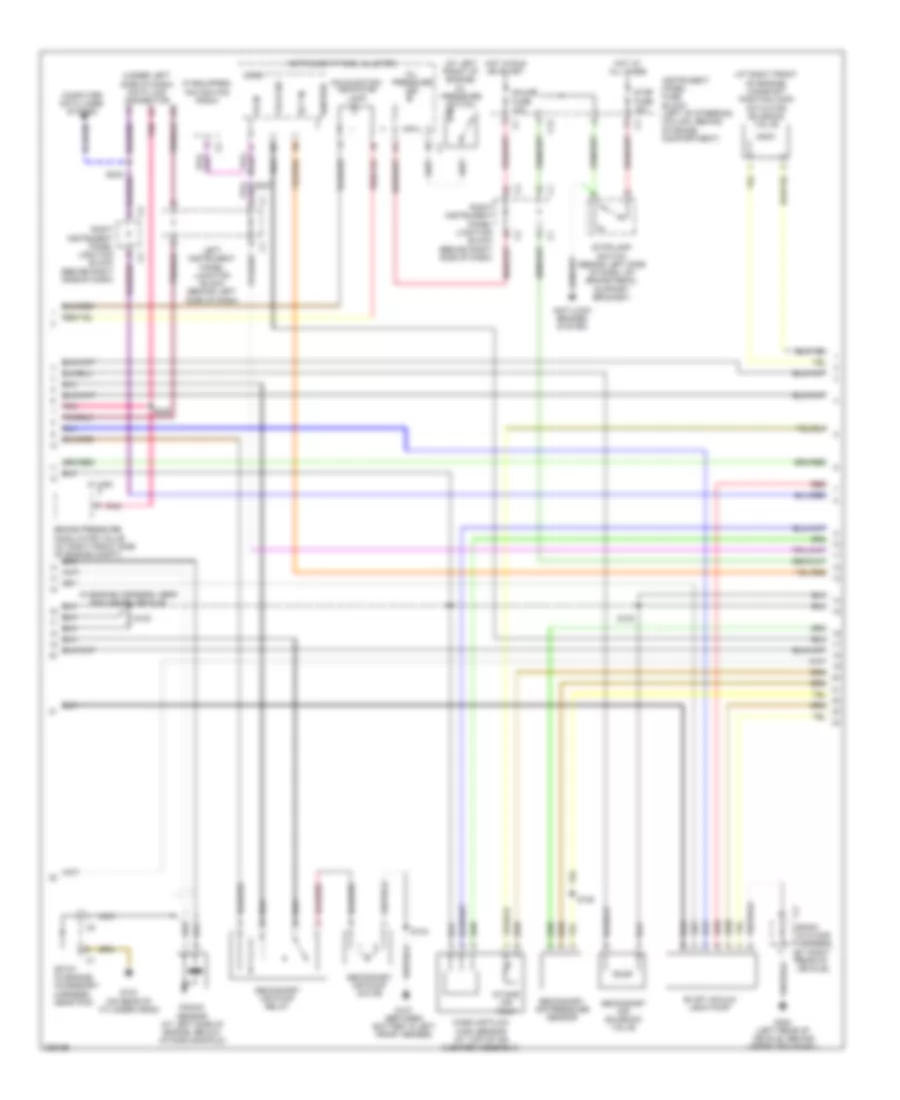
1.8L VIN 8, Engine Performance Wiring Diagram, AWD (2 of 3) for Pontiac Vibe GT 2006
 https://portal-diagnostov.com/license.html
Automotive Electricians Portal FZCO
Automotive Electricians Portal FZCO
https://portal-diagnostov.com/license.html
https://portal-diagnostov.com/license.html
Automotive Electricians Portal FZCO
Automotive Electricians Portal FZCOList of elements for 1.8L VIN 8, Engine Performance Wiring Diagram, AWD (2 of 3) for Pontiac Vibe GT 2006:
- (front center of engine compt, below intake manifold)
- (in engine accessory harness near pcm) sp108
- (in engine accessory harness, near pcm) sp107
- (in engine harness, near pcm inside vehicle)
- (left side of cylinder head)
- (on front of transaxle) park/neutral position switch
- (under left side of dash) data link connector (dlc)
- 2nd brake solenoid
- Anti-lock brakes system
- Brake pressure modulator valve (at right front side of engine compt)
- C11
- C12
- Computer data lines system
- Cruise control module (behind left side of dash, top of steering column bracket)
- Ect in
- Evap canister purge solenoid valve (left side of engine compartment, next to air cleaner)
- G104
- Gauge fuse 10a
- Hot at all times
- Hot in run or start
- Ignition
- Instrument panel cluster
- Instrument panel fuse block (left of steering column, behind storage compartment)
- Intake air temp
- Knock sensor
- Left instrument panel junction block (behind left side of dash)
- Line pressure control solenoid
- Logic
- Malfunction indicator lamp
- Mass air flow sensor (top of air cleaner assembly)
- Navigation radio (if equipped)
- Nca
- O/d off ind
- Pnk
- Red
- Right instrument panel junction block (behind right side of dash)
- S100
- S218
- S227
- S229
- Shift solenoid
- Sp107 (in engine accessory harness, near pcm)
- Stop fuse 15a
- Stoplamp switch (behind left side of dash, on brake pedal support bracket)
- Tach in
- Tcc solenoid
- Transmission connector
- Transmission fluid temperature sensor
- Vs in
- W/ vsc
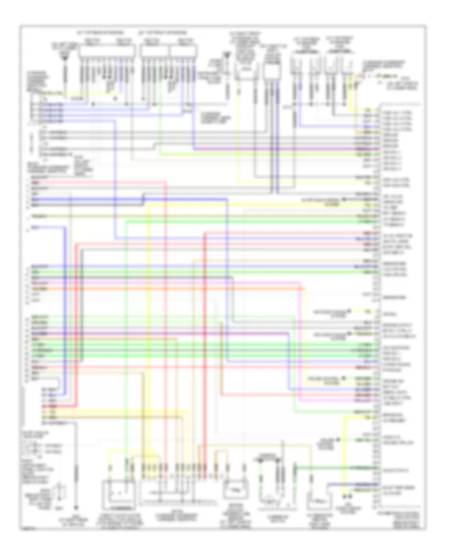
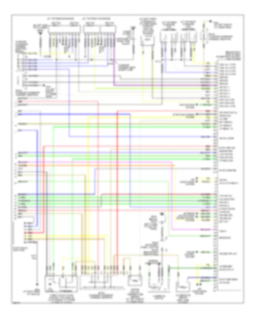
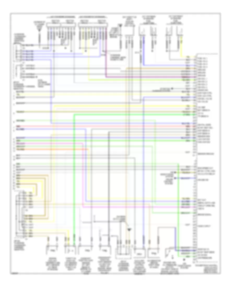
1.8L VIN 8, Engine Performance Wiring Diagram, AWD (3 of 3) for Pontiac Vibe GT 2006
 https://portal-diagnostov.com/license.html
Automotive Electricians Portal FZCO
Automotive Electricians Portal FZCO
https://portal-diagnostov.com/license.html
https://portal-diagnostov.com/license.html
Automotive Electricians Portal FZCO
Automotive Electricians Portal FZCOList of elements for 1.8L VIN 8, Engine Performance Wiring Diagram, AWD (3 of 3) for Pontiac Vibe GT 2006:
- (at right front of engine, on cylinder head) camshaft position actuator solenoid valve
- (at right rear of vehicle)
- (at top front of engine)
- (at top front of engine) fuel injectors
- (at top rear of engine)
- (at top rear of engine) fuel injectors
- (behind right side of dash)
- (in engine accessory harness, near pcm) sp107
- (in engine accessory harness, near pcm) sp108
- (in engine harness, near noise filter)
- (on left side of cylinder head)
- (on left side of cylinder head) g105
- (on throttle body) idle air control valve
- +5v ref
- A/c resistor (behind right side of dash)
- Ac clutch relay
- Ac on sig
- Ac request
- Air conditioning system
- Brake sig
- Cmp high ctrl
- Cmp low ctrl
- Cmp sen in
- Co relay ctrl
- Crank sig
- Cruise control system
- Cruise ctrl sw
- Cruise ind
- D position sig
- Ect out
- Ect sens in
- Efi rly ctrl hi
- Engine coolant temperature sensor (at left side of cylinder head)
- Engine output
- Evap temp sens
- Evap vacuum leak pump
- Evap vent sol
- Fuel inj 1 ctrl
- Fuel inj 2 ctrl
- Fuel inj 3 ctrl
- Fuel inj 4 ctrl
- G104
- G105 (on left side of cylinder head)
- G106
- G201
- G301
- Ground
- High maf sig
- Ho2s 2 in
- Iac valve
- Iat sens in
- Ig vol positive
- Ign coil 1
- Ign coil 2
- Ign coil 3
- Ign coil 4
- Ign fail safe
- Ign sol
- Ignition coil 1
- Ignition coil 2
- Ignition coil 3
- Ignition coil 4
- Interior lights system
- Low maf sig
- Nca
- Noise filter (in instrument panel fuse block)
- O/d indicator
- Od switch in
- Overdrive switch
- Pnp sw 2
- Pnp sw l
- Powertrain control module (pcm)
- R pos sig
- Red
- Right instrument panel junction block (behind right side of dash)
- S105
- S106
- S114
- Sensor gnd
- Serial data
- Sp107 (in engine accessory harness, near pcm)
- Sp108 (in engine accessory harness, near pcm)
- Sp201 (behind right body hinge pillar trim panel)
- Spark plug
- Starting/charging system
- Throttle actuator control (tac) module (lf of engine, attached to throttle body)
- Tp sens in
- Tp sensor
- Vss input
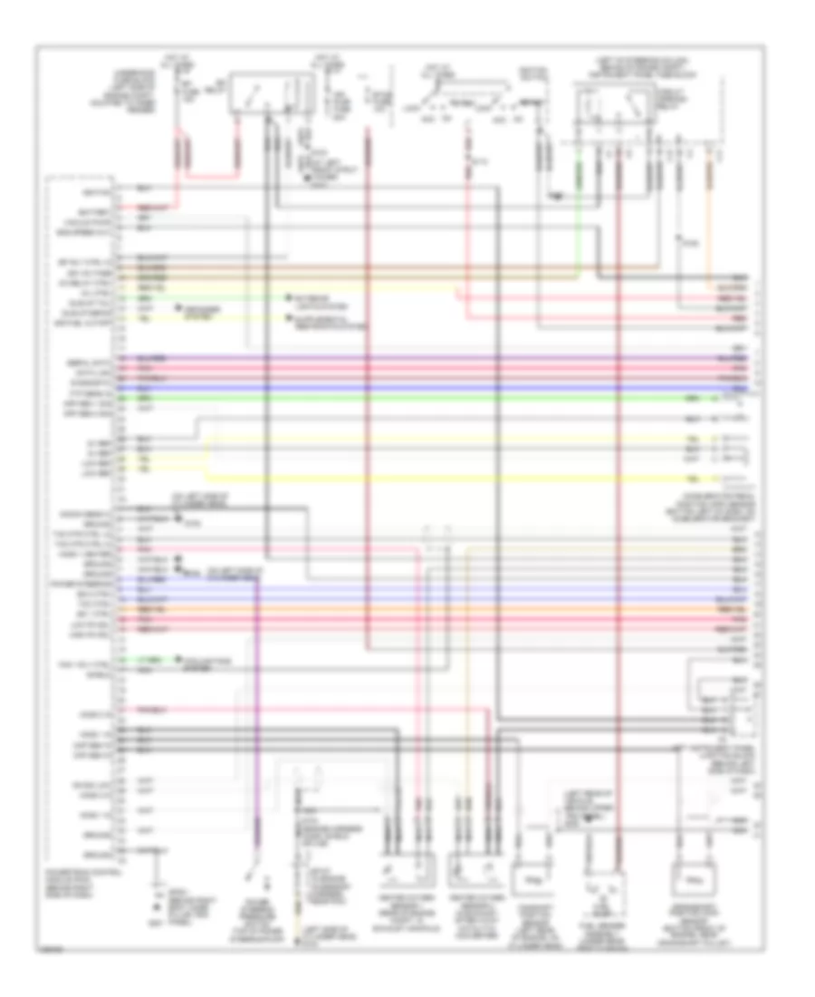
1.8L VIN 8, Engine Performance Wiring Diagram, FWD (1 of 3) for Pontiac Vibe GT 2006
 https://portal-diagnostov.com/license.html
Automotive Electricians Portal FZCO
Automotive Electricians Portal FZCO
https://portal-diagnostov.com/license.html
https://portal-diagnostov.com/license.html
Automotive Electricians Portal FZCO
Automotive Electricians Portal FZCOList of elements for 1.8L VIN 8, Engine Performance Wiring Diagram, FWD (1 of 3) for Pontiac Vibe GT 2006:
- (at left front strut tower) g103
- (left of steering column, behind storage compt) instrument panel fuse block
- (left rear of vehicle, behind upper trim panel) g300
- (left side of cylinder head) g104
- (on left side of cylinder head)
- 5v ref
- Acc
- Accelerator pedal position (app) sensor (bottom left of dash, on accelerator bracket)
- Air pump fuse 50a
- App sen 1 sig
- App sen 2 sig
- Battery
- C11
- C12
- Camshaft position sensor (left rear of engine, on cylinder head)
- Circuit opening relay
- Ckp sen in
- Cmp sen in
- Co relay ctrl
- Cooling fans system
- Crankshaft position (ckp) sensor (bottom front of engine, near crankshaft pulley)
- Data link
- Defogger system
- Diagnostic
- Efi fuse 15a
- Efi relay
- Efi rly ctrl hi
- Eng speed out
- Etcs fuse 10a
- Exterior lights system
- Fan 1 rly ctrl
- Ftp sens in
- Fuel pump
- Fuel sender assembly (under rear seat cushion)
- G104
- G105
- G201
- Ground
- Heated oxygen sensor 1 (rear of engine compt, in exhaust manifold)
- Heated oxygen sensor 2 (in exhaust, after 3-way catalytic converter)
- High pc sol
- Ho2s 1 heater
- Ho2s 1 in
- Ho2s 2 in
- Hot at all times
- Idle-up defog
- Idle-up tail
- Ign voltage
- Ignition
- Ignition switch
- Knock sens hi
- Ks sig low
- Left instrument panel junction block (behind left side of dash)
- Lock
- Low pc sol
- Low ref
- Mil ctrl
- Nca
- Pnk
- Power steering
- Power steering pressure switch (top of power steering pump)
- Powertrain control module (pcm) (behind right side of dash)
- Red
- S103
- S104 (engine harness ho2s1 shield splice)
- S110
- S125
- S237
- Serial data
- Shield
- Sir fuel cutoff
- Sp107 (in engine accessory harness, c1 near pcm)
- Sp201 (behind right body hinge pillar trim panel)
- Ss 1 ctrl
- Ss 2 ctrl
- Start
- Tac mtr ctrl hi
- Tac mtr ctrl lo
- Tcc ctrl
- Underhood fuse block (left side of engine compt, mounted to inner fender)
- Vacuum pump
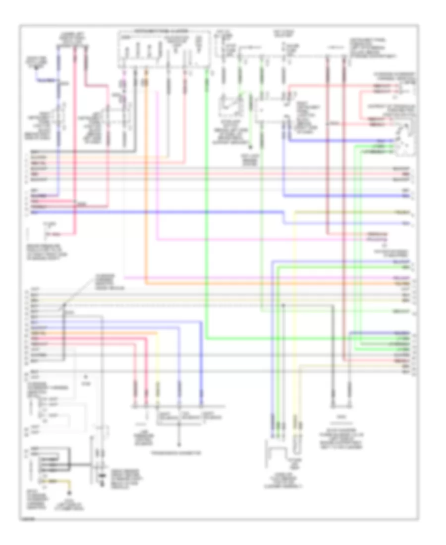
1.8L VIN 8, Engine Performance Wiring Diagram, FWD (2 of 3) for Pontiac Vibe GT 2006
 https://portal-diagnostov.com/license.html
Automotive Electricians Portal FZCO
Automotive Electricians Portal FZCO
https://portal-diagnostov.com/license.html
https://portal-diagnostov.com/license.html
Automotive Electricians Portal FZCO
Automotive Electricians Portal FZCOList of elements for 1.8L VIN 8, Engine Performance Wiring Diagram, FWD (2 of 3) for Pontiac Vibe GT 2006:
- (in engine accessory harness, near pcm) sp107
- (in engine accessory harness, near pcm) sp108
- (in engine harness, near pcm inside vehicle)
- (on front of transaxle) park/neutral position switch
- (under left side of dash) data link connector (dlc)
- Anti-lock brakes system
- Brake pressure modulator valve (at right front side of engine compt)
- C11
- C12
- Computer data lines system
- Ect in
- Evap canister purge solenoid valve (left side of engine compartment, next to air cleaner)
- G104 (left side of cylinder head)
- Gauge fuse 10a
- Hot at all times
- Hot in run or start
- Ignition
- Instrument panel cluster
- Instrument panel fuse block (left of steering column, behind storage compartment)
- Intake air temp
- Knock sensor (front center of engine compt, below intake manifold)
- Left instrument panel junction block (behind left side of dash)
- Line pressure control solenoid
- Logic
- Malfunction indicator lamp
- Mass air flow sensor (top of air cleaner assembly)
- Navigation radio (if equipped)
- Nca
- O/d off ind
- Pnk
- Red
- Right instrument panel junction block (behind right side of dash)
- S100
- S126
- S218
- S227
- S229
- Shift solenoid
- Sp107 (in engine accessory harness, near pcm)
- Stop fuse 15a
- Stoplamp switch (behind left side of dash, on brake pedal support bracket)
- Tach in
- Tcc solenoid
- Transmission connector
- Vs in
- W/ vsc
1.8L VIN 8, Engine Performance Wiring Diagram, FWD (3 of 3) for Pontiac Vibe GT 2006
 https://portal-diagnostov.com/license.html
Automotive Electricians Portal FZCO
Automotive Electricians Portal FZCO
https://portal-diagnostov.com/license.html
https://portal-diagnostov.com/license.html
Automotive Electricians Portal FZCO
Automotive Electricians Portal FZCOList of elements for 1.8L VIN 8, Engine Performance Wiring Diagram, FWD (3 of 3) for Pontiac Vibe GT 2006:
- (at right front of engine, on cylinder head) camshaft position actuator solenoid valve
- (at top front of engine)
- (at top front of engine) fuel injectors
- (at top rear of engine)
- (at top rear of engine) fuel injectors
- (behind right side of dash) powertrain control module (pcm)
- (in engine accessory harness, near pcm) sp108
- (in engine harness, near noise filter)
- (on left side of cylinder head) g105
- +5v ref
- A/c resistor (behind right side of dash)
- Ac clutch relay
- Ac on sig
- Ac request
- Air conditioning system
- Brake sig
- Cmp high ctrl
- Cmp low ctrl
- Cooling fans system
- Crank sig
- Cruise control system
- Cruise ctrl
- Cruise ctrl sw
- Cruise ind
- D position sig
- Ect out
- Ect sens in
- Engine coolant temperature sensor (at left side of cylinder head)
- Evap canister
- Evap temp sens
- Evap vacuum leak pump
- Evap vent sol
- Exterior lights system cruise control system
- Fan 2 rly ctrl
- Fuel inj 1 ctrl
- Fuel inj 2 ctrl
- Fuel inj 3 ctrl
- Fuel inj 4 ctrl
- G104 (on left side of cylinder head)
- G105 (on left side of cylinder head)
- G106
- G201
- G301 (at right rear of vehicle)
- Ground
- High maf sig
- Iat sens in
- Ign coil 1
- Ign coil 2
- Ign coil 3
- Ign coil 4
- Ign fail safe
- Ign positive vol
- Ign sol
- Ignition coil 1
- Ignition coil 2
- Ignition coil 3
- Ignition coil 4
- Interior lights system
- Low maf sig
- Nca
- Noise filter (in instrument panel fuse block)
- O/d indicator
- Od switch in
- Overdrive switch
- Plug spark
- Pnp sw 2
- Pnp sw l
- R pos sig
- Red
- Right instrument panel junction block (behind right side of dash)
- S105
- S106
- S114
- Sensor gnd
- Sp107 (in engine accessory harness, near pcm)
- Sp108 (in engine accessory harness, near pcm)
- Sp201 (behind right body hinge pillar trim panel)
- Spark plug
- Starting/charging system
- Tac ign vol
- Tac motor
- Throttle actuator control (tac) module (lf of engine, attached to throttle body)
- Tp sen 2 sig
- Tp sens 1 in
- Tp sensor
- Vss in
1.8L VIN L
1.8L VIN L, Engine Performance Wiring Diagram (1 of 3) for Pontiac Vibe GT 2006
 https://portal-diagnostov.com/license.html
Automotive Electricians Portal FZCO
Automotive Electricians Portal FZCO
https://portal-diagnostov.com/license.html
https://portal-diagnostov.com/license.html
Automotive Electricians Portal FZCO
Automotive Electricians Portal FZCOList of elements for 1.8L VIN L, Engine Performance Wiring Diagram (1 of 3) for Pontiac Vibe GT 2006:
- (at left front strut tower) g103
- (engine harness ho2s1 shield splice) s104
- Ac request sig
- Acc
- Air conditioning system
- Air pump fuse 50a
- Air pump rel
- Air sol ctrl
- Battery
- C11
- C12
- Circuit opening relay
- Cooling fans system
- Defogger system
- Diagnostic
- Efi fuse 15a
- Efi relay
- Evap canister purge solenoid valve (at left side of engine compt, next to air cleaner)
- Evap purge sol
- Exterior lights system
- Fan 1 rly ctrl
- Fan 2 rly ctrl
- Ftp sig
- Fuel pump
- Fuel sender assembly (under rear seat cushion, beneath access panel on top of fuel tank)
- G104 (on rear of cylinder head)
- G105 (on rear of cylinder head)
- G201
- G300 (left rear of vehicle, behind upper trim panel)
- Ground
- Heated oxygen sensor 1 (at rear of engine compartment, in exhaust manifold)
- Heated oxygen sensor 2 (below vehicle, in exhaust pipe after three way catalytic converter)
- Hi rocker arm
- Ho2s 1 htr
- Ho2s 1 in
- Ho2s 2 htr
- Hot at all times
- Idle-up defog
- Idle-up tail
- Ign
- Ignition
- Ignition switch
- Instrument panel fuse block (left of steering column, behind storage compartment)
- Knock sens hi
- Knock sens lo
- Left instrument panel junction block (behind left side of dash)
- Lock
- Low rocker arm
- Mil ctrl
- Pnk
- Power steering pressure switch (at top of power steering pump)
- Powertrain control module (pcm) (behind right side of dash)
- Psp signal
- Red
- Rocker arm oil control valve solenoid (on left side of cylinder head)
- S116
- S237
- Sir fuel cutoff
- Sp107 (in engine accessory harness, near pcm)
- Sp201 (behind right body hinge pillar trim panel)
- Start
- Underhood fuse block (left side of engine compartment, mounted to inner fender)
- Vacuum pump
1.8L VIN L, Engine Performance Wiring Diagram (2 of 3) for Pontiac Vibe GT 2006
 https://portal-diagnostov.com/license.html
Automotive Electricians Portal FZCO
Automotive Electricians Portal FZCO
https://portal-diagnostov.com/license.html
https://portal-diagnostov.com/license.html
Automotive Electricians Portal FZCO
Automotive Electricians Portal FZCOList of elements for 1.8L VIN L, Engine Performance Wiring Diagram (2 of 3) for Pontiac Vibe GT 2006:
- (at left front of engine) oil pressure switch
- (at right front of engine) camshaft position (cmp) actuator solenoid valve
- (if equipped) navigation radio
- (in engine harness, near pcm inside vehicle)
- (under left side of dash) data link connector
- Anti-lock brakes system
- Brake pressure modulator valve (at right front side of engine compt)
- C12
- Computer data lines system
- Ect in
- Evap vacuum leak pump
- G104 (on rear of cylinder head)
- G107 (between battery & left front fender)
- G300 (left rear of vehicle, behind upper trim panel)
- Gauge fuse 10a
- Hot at all times
- Hot in run or start
- Ignition
- Instrument panel cluster
- Instrument panel fuse block (left of steering column, behind storage compartment)
- Intake air temp
- Knock sensor (at left side of engine, below intake manifold)
- Left instrument panel junction block (behind left side of dash)
- Logic
- Malfunction indicator lamp
- Mass air flow (maf) sensor (at top of air cleaner assembly)
- Nca
- Oil pressure ind
- Pnk
- Red
- Right instrument panel junction block (behind right side of dash)
- S100
- S124
- S128
- S227
- S229
- Secondary air pressure sensor
- Secondary air pump motor
- Secondary air pump relay
- Secondary air solenoid valve
- Sp107 (in engine accessory harness, near pcm)
- Sp300 (in floor harness, at right c1 rear of vehicle)
- Stop fuse 15a
- Stoplamp switch (behind left side of dash, on brake pedal support bracket)
- Tach sig
- Vs in
- W/ vsc
1.8L VIN L, Engine Performance Wiring Diagram (3 of 3) for Pontiac Vibe GT 2006
 https://portal-diagnostov.com/license.html
Automotive Electricians Portal FZCO
Automotive Electricians Portal FZCO
https://portal-diagnostov.com/license.html
https://portal-diagnostov.com/license.html
Automotive Electricians Portal FZCO
Automotive Electricians Portal FZCOList of elements for 1.8L VIN L, Engine Performance Wiring Diagram (3 of 3) for Pontiac Vibe GT 2006:
- (at top front of engine)
- (at top front of engine) fuel injectors
- (at top rear of engine)
- (at top rear of engine) fuel injectors
- (in engine accessory harness, near pcm) sp108
- (in engine harness, near noise filter)
- (on rear of cylinder head)
- (on rear of cylinder head) g105
- (on throttle body) idle air control (iac) valve
- +5v ref
- A/c resistor (behind right side of dash)
- Ac clutch relay
- Ac on sig
- Air conditioning system
- Air pressure
- Air sol valve
- Auxiliary intake air control solenoid (at front of air cleaner assembly)
- Brake signal
- Camshaft position (cmp) sensor (at left rear of engine, on cylinder head)
- Circuit open rel
- Ckp sens in
- Cmp high ctrl
- Cmp low ctrl
- Cmp sens in
- Crank sig
- Crankshaft position (ckp) sensor (at bottom front of engine, near crankshaft pulley)
- Cruise control system
- Cruise ind
- Ect out
- Ect sens in
- Efi rly ctrl high
- Eng speed out
- Engine coolant temperature (ect) sensor (at rear of engine)
- Evap temp sens
- Evap vent sol
- Fuel inj 1
- Fuel inj 2
- Fuel inj 3
- Fuel inj 4
- G104
- G105 (on rear of cylinder head)
- G106
- Ground
- High maf sig
- Ho2s 2 input
- Iac valve
- Iat in
- Ign coil 1
- Ign coil 2
- Ign coil 3
- Ign coil 4
- Ign fail safe
- Ignition coil 1
- Ignition coil 2
- Ignition coil 3
- Ignition coil 4
- Low maf sig
- Nca
- Noise filter (at left rear of engine)
- Plug spark
- Powertrain control module (pcm) (behind right side of dash)
- Raop sw in
- Red
- Rocker arm oil pressure switch (on right side of engine, mounted on cylinder head)
- S105
- S106
- S114
- Sensor gnd
- Sensor ground
- Serial data line
- Sp107 (in engine accessory harness, near pcm)
- Sp108 (in engine accessory harness, near pcm)
- Spark plug
- Starting/ charging system
- Throttle position (tp) sensor (on rear of throttle body)
- Tp sens in
- Vss in

 Čeština
 Dansk
Dansk Deutsch
 Ελληνικά
 English
 English
 Español
 Suomi
Suomi Français
 Français
 עברית
עברית Hrvatski
 Magyar
 Italiano
 日本語
日本語 한국어
한국어 Nederlands
 Polski
 Português
 Português
 Română
 Русский
 Slovenčina
 Slovenščina
 Svenska
 Türkçe
