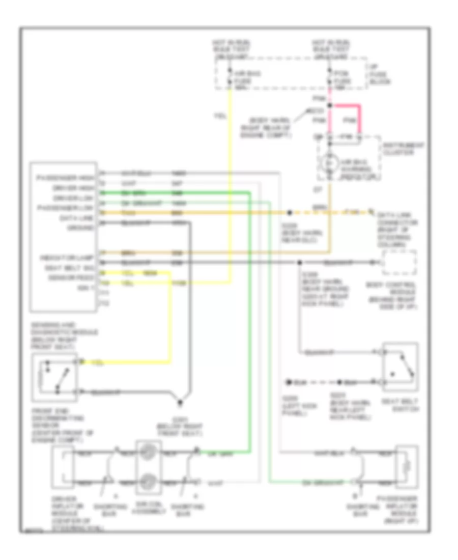
SUPPLEMENTAL RESTRAINTS
Supplemental Restraint Wiring Diagram for Pontiac Bonneville SE 1997
 https://portal-diagnostov.com/license.html
Automotive Electricians Portal FZCO
Automotive Electricians Portal FZCO
https://portal-diagnostov.com/license.html
https://portal-diagnostov.com/license.html
Automotive Electricians Portal FZCO
Automotive Electricians Portal FZCO
List of elements for Supplemental Restraint Wiring Diagram for Pontiac Bonneville SE 1997:
- (body harn, right rear of engine compt)
- Air bag fuse 10a
- Air bag warning indicator
- B nca
- Bar
- Body control module (behind right side of i/p)
- Data line
- Data link connector (right of steering column)
- Driver high
- Driver inflator module (center of steering whl)
- Driver low
- F16
- Front end discriminating sensor (center front of engine compt)
- G200 (left kick panel)
- G301 (below right front seat)
- Ground
- Hot in run, bulb test or start
- I/p fuse block
- Ign 1
- Indicator lamp
- Instrument cluster
- Nca
- Passenger high
- Passenger inflator module (right i/p)
- Passenger low
- Pcm fuse 10a
- Pnk
- S225 (body harn, near left kick panel)
- S226 (body harn, near dlc)
- S233
- S309 (body harn, near ground g203 at right kick panel)
- Seat belt sig
- Seat belt switch
- Sensing and diagnostic module (below right front seat)
- Sensor feed
- Shorting
- Sir coil assembly
- Tan
 Čeština
 Dansk
Dansk Deutsch
 Ελληνικά
 English
 English
 Español
 Suomi
Suomi Français
 Français
 עברית
עברית Hrvatski
 Magyar
 Italiano
 日本語
日本語 한국어
한국어 Nederlands
 Polski
 Português
 Português
 Română
 Русский
 Slovenčina
 Slovenščina
 Svenska
 Türkçe
 中文 (中国)
