ENGINE PERFORMANCE
2.0L SKYACTIV
2.0L SKYACTIV, Engine Performance Wiring Diagram (1 of 5) for Mazda 3 Touring 2014
 https://portal-diagnostov.com/license.html
Automotive Electricians Portal FZCO
Automotive Electricians Portal FZCO
https://portal-diagnostov.com/license.html
https://portal-diagnostov.com/license.html
Automotive Electricians Portal FZCO
Automotive Electricians Portal FZCO
List of elements for 2.0L SKYACTIV, Engine Performance Wiring Diagram (1 of 5) for Mazda 3 Touring 2014:
- (center left side of engine) knock sensor
- (center of left side of engine) crankshaft position sensor
- (front left of top of engine) a/f sensor
- (left rear of cylinder head) intake camshaft position sensor
- (on top of engine)
- (right rear of cylinder head) exhaust camshaft position sensor
- 0140-101a
- 0940-101b
- 1aa
- 1ab
- 1ac
- 1ad
- 1ae
- 1af
- 1ag
- 1ah
- 1ai
- 1aj
- 1ak
- 1al
- 1am
- 1an
- 1ao
- 1ap
- 1aq
- 1ar
- 1as
- 1at
- 1au
- 1av
- 1aw
- 1ax
- 1ay
- 1az
- 1ba
- 1bb
- 1bc
- 1bd
- 1be
- 1bf
- 1bg
- 1bh
- C-01
- Computer data lines system
- Engine coolant temperature sensor 1 (right rear of engine)
- Exterior lights system
- Fbcm (left rear corner of engine compt)
- G08 (left rear of engine)
- Ic igniter ion sensor
- Ignition coil 1
- Ignition coil 2
- Ignition coil 3
- Ignition coil 4
- Nca
- Pcm (left rear of engine compt)
- Pnk
- Red
- Starting/charging system
- Tan
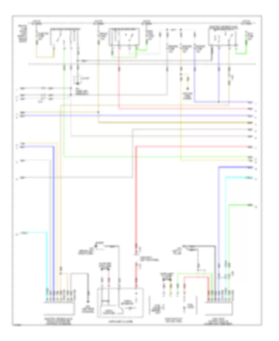
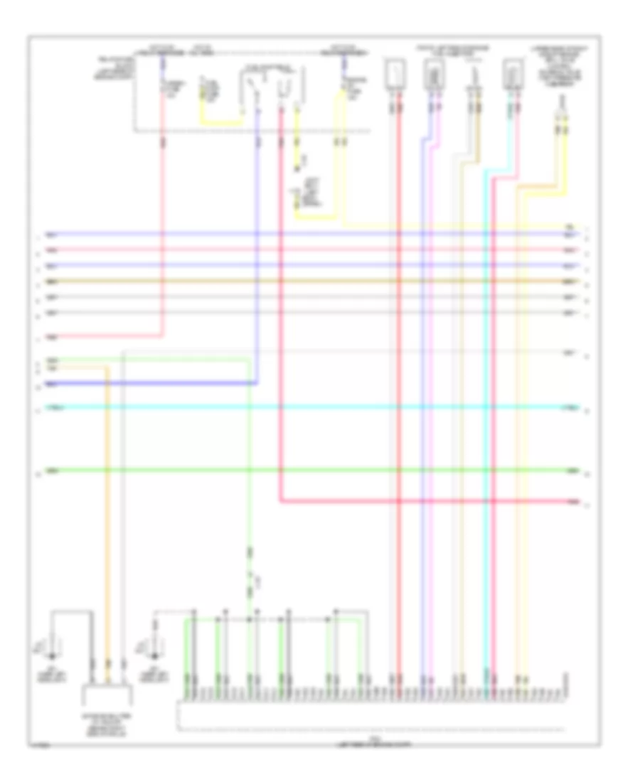
2.0L SKYACTIV, Engine Performance Wiring Diagram (2 of 5) for Mazda 3 Touring 2014
 https://portal-diagnostov.com/license.html
Automotive Electricians Portal FZCO
Automotive Electricians Portal FZCO
https://portal-diagnostov.com/license.html
https://portal-diagnostov.com/license.html
Automotive Electricians Portal FZCO
Automotive Electricians Portal FZCOList of elements for 2.0L SKYACTIV, Engine Performance Wiring Diagram (2 of 5) for Mazda 3 Touring 2014:
- (left rear of engine compt) (w/ i-eloop) current sensor
- (left side of engine) throttle body
- (on transaxle) (m/t) neutral switch
- (right front of engine) oil control valve
- (top left side of engine) engine oil solenoid valve
- (upper right rear of engine) purge solenoid valve
- 0140-101a
- 1bi
- 1bj
- 1bk
- 1bl
- 1bm
- 1bn
- 1bo
- 1bp
- 1bq
- 1br
- 1bs
- 1bt
- 1bu
- 1bv
- 1bw
- 1bx
- 1by
- 1bz
- 1ca
- 1cb
- 1cc
- 1cd
- 1ce
- 1cf
- 1cg
- 1ch
- 1ci
- 1cj
- 1ck
- 1cl
- 1cm
- 1cn
- C-52
- Fuel pressure sensor (left front of engine)
- G01 (near left headlight)
- G08 (left rear of engine)
- J/c g01
- Joint box 1 (left kick c-52 panel)
- Manifold absolute pressure sensor/ intake air temperature sensor 2 (intake manifold)
- Oil pressure switch (center of left side of engine)
- Pcm (left rear of engine compt)
- Pnk
- Red
- Starting/charging system
- Tan
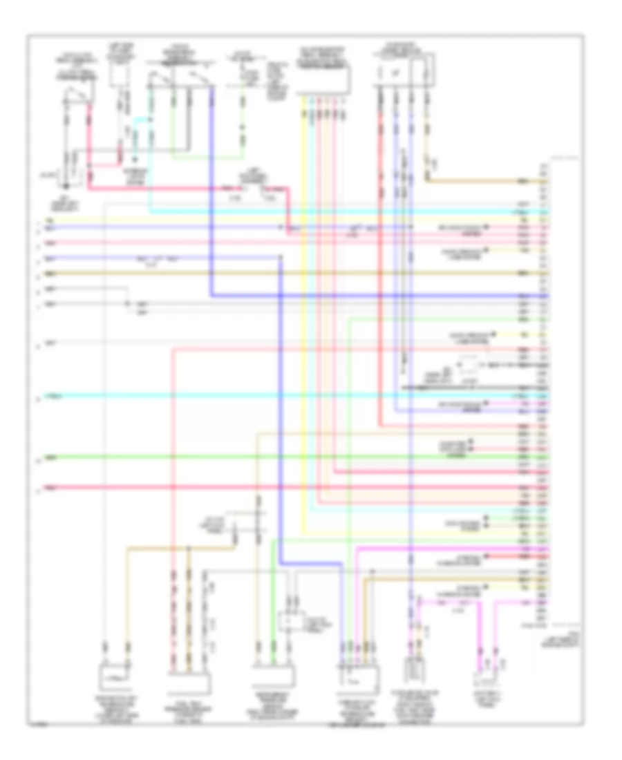
2.0L SKYACTIV, Engine Performance Wiring Diagram (3 of 5) for Mazda 3 Touring 2014
 https://portal-diagnostov.com/license.html
Automotive Electricians Portal FZCO
Automotive Electricians Portal FZCO
https://portal-diagnostov.com/license.html
https://portal-diagnostov.com/license.html
Automotive Electricians Portal FZCO
Automotive Electricians Portal FZCOList of elements for 2.0L SKYACTIV, Engine Performance Wiring Diagram (3 of 5) for Mazda 3 Touring 2014:
- 0114-102a
- 0114-102b
- 0140-119a
- 0140-119b
- C-01
- C-05
- C-52
- C-54
- Check engine ind
- Computer data lines system
- Cooling fans system
- Electric variable valve timing motor/driver (top front of engine)
- Electric variable valve timing relay (evvt)
- Eng main fuse 40a
- Eng+b fuse 7.5a
- Engine1 fuse 15a
- Engine2 fuse 15a
- Engine3 fuse 15a
- Evvt fuse 20a
- Fuel gauge sender unit
- Fuel injector relay (inj)
- Fuel pump
- Fuel pump control module (under right rear seat)
- Fuel pump unit (on fuel tank)
- G01 (near left headlight)
- G08 (left rear of engine)
- G10 (behind left side of dash)
- G18 (left "c" pillar)
- Hot at all times
- Injector fuse 30a
- Instrument cluster
- Instrument cluster system
- J/c g01
- J/c g10
- Joint box 1 (left kick panel)
- Main relay (eng main)
- Micro- computer
- Pnk
- Red
- Relay & fuse block (left rear of engine compt)
- Tan
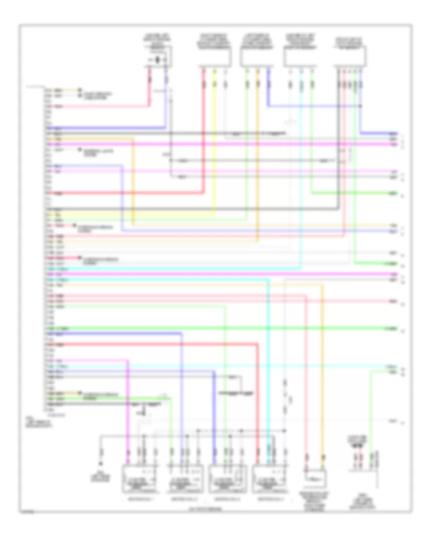
2.0L SKYACTIV, Engine Performance Wiring Diagram (4 of 5) for Mazda 3 Touring 2014
 https://portal-diagnostov.com/license.html
Automotive Electricians Portal FZCO
Automotive Electricians Portal FZCO
https://portal-diagnostov.com/license.html
https://portal-diagnostov.com/license.html
Automotive Electricians Portal FZCO
Automotive Electricians Portal FZCOList of elements for 2.0L SKYACTIV, Engine Performance Wiring Diagram (4 of 5) for Mazda 3 Touring 2014:
- (top of left side of engine) fuel injectors
- (upper rear of right side of engine) spill valve control solenoid valve (high pressure fuel pump)
- 0140-101a
- 1co
- 1cp
- 1cq
- 1cr
- 1cs
- 1ct
- 1cu
- 1cv
- 1cw
- 1cx
- 1cy
- 1cz
- 1da
- 1db
- 1dc
- 1dd
- 1de
- 1df
- 1dg
- 1dh
- 1di
- 1dj
- 1dk
- 1dl
- 1dm
- 1dn
- 1do
- 1dp
- 1dq
- 1dr
- 1ds
- 1dt
- 1du
- 1dv
- 1dw
- 1dx
- 1dy
- 1dz
- 1ea
- 1eb
- 1ec
- 1ed
- 1ee
- 1ef
- 1eg
- 1eh
- 1ei
- 1ej
- A tan
- Active air shutter (w/ i-eloop) (behind right side of grille)
- B pnk
- B red
- C-01
- C-52
- Engine ig1 fuse 15a
- Fuel pump fuse 15a
- Fuel pump relay
- G01 (near left headlight)
- Hot at all times
- Hot w/ ig1 relay energized
- J/c g01
- Joint box 1 (left kick c-51
- Meter 1 fuse 10a
- Panel)
- Pcm (left rear of engine compt)
- Pnk
- Red
- Relay & fuse block (left rear of engine compt)
- Tan
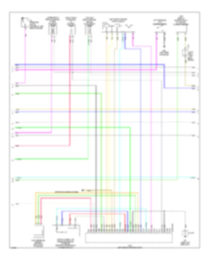
2.0L SKYACTIV, Engine Performance Wiring Diagram (5 of 5) for Mazda 3 Touring 2014
 https://portal-diagnostov.com/license.html
Automotive Electricians Portal FZCO
Automotive Electricians Portal FZCO
https://portal-diagnostov.com/license.html
https://portal-diagnostov.com/license.html
Automotive Electricians Portal FZCO
Automotive Electricians Portal FZCOList of elements for 2.0L SKYACTIV, Engine Performance Wiring Diagram (5 of 5) for Mazda 3 Touring 2014:
- (in exhaust, under vehicle) ho2s
- (left kick panel) joint box 1
- (left side of dash) stop/start unit
- (on accelerator pedal assembly) accelerator pedal position sensor
- (on clutch pedal assembly) (m/t) clutch pedal position switch
- (top of brake pedal assembly) brake switch
- 0140-101b
- 0940-103b
- 2aa
- 2ab
- 2ac
- 2ad
- 2ae
- 2af
- 2ag
- 2ah
- 2ai
- 2aj
- 2ak
- 2al
- 2am
- 2an
- 2ao
- 2ap
- 2aq
- 2ar
- 2as
- 2at
- 2au
- 2av
- 2aw
- 2ax
- 2ay
- 2az
- 2ba
- 2bb
- 2bc
- 2bd
- 2be
- 2bf
- 2bg
- 2bh
- Air conditioning system
- C-03
- C-05
- C-24
- C-31
- C-52
- C-56
- Computer data lines system
- Cooling fans system
- Cv solenoid valve (if equipped) (right side of fuel tank, near quick release connector)
- Engine coolant temperature sensor 2 (lower left side of radiator)
- Exterior lights system
- Fuel tank pressure sensor (in rear of fuel tank)
- G01 (near left headlight)
- H red
- Hot at all times
- J c-01
- J/c c-32 (left kick panel)
- J/c g01
- Joint box 1 (left kick panel)
- Mass air flow/ intake air temperature sensor 1 (air cleaner housing)
- Nca
- Pcm (left rear of engine compt)
- Pnk
- Red
- Red c
- Refrigerant pressure sensor (right rear corner of engine compt)
- Relay & fuse block (left rear of engine compt)
- Starting/ charging system
- Stop fuse 10a
- Tan
- Tan b
2.5L
2.5L, Engine Performance Wiring Diagram (1 of 5) for Mazda 3 Touring 2014
 https://portal-diagnostov.com/license.html
Automotive Electricians Portal FZCO
Automotive Electricians Portal FZCO
https://portal-diagnostov.com/license.html
https://portal-diagnostov.com/license.html
Automotive Electricians Portal FZCO
Automotive Electricians Portal FZCOList of elements for 2.5L, Engine Performance Wiring Diagram (1 of 5) for Mazda 3 Touring 2014:
- (center left side of engine) knock sensor
- (center of left side of engine) crankshaft position sensor
- (front left of top of engine) a/f sensor
- (left rear of cylinder head) intake camshaft position sensor
- (on top of engine)
- (right rear of cylinder head) exhaust camshaft position sensor
- 0140-101a
- 0940-101b
- 1aa
- 1ab
- 1ac
- 1ad
- 1ae
- 1af
- 1ag
- 1ah
- 1ai
- 1aj
- 1ak
- 1al
- 1am
- 1an
- 1ao
- 1ap
- 1aq
- 1ar
- 1as
- 1at
- 1au
- 1av
- 1aw
- 1ax
- 1ay
- 1az
- 1ba
- 1bb
- 1bc
- 1bd
- 1be
- 1bf
- 1bg
- 1bh
- C-01
- Computer data lines system
- Engine coolant temperature sensor 1 (right rear of engine)
- Exterior lights system
- Fbcm (left rear corner of engine compt)
- G08 (left rear of engine)
- Ic igniter ion sensor
- Ignition coil 1
- Ignition coil 2
- Ignition coil 3
- Ignition coil 4
- Nca
- Pcm (left rear of engine compt)
- Pnk
- Red
- Starting/charging system
- Tan
2.5L, Engine Performance Wiring Diagram (2 of 5) for Mazda 3 Touring 2014
 https://portal-diagnostov.com/license.html
Automotive Electricians Portal FZCO
Automotive Electricians Portal FZCO
https://portal-diagnostov.com/license.html
https://portal-diagnostov.com/license.html
Automotive Electricians Portal FZCO
Automotive Electricians Portal FZCOList of elements for 2.5L, Engine Performance Wiring Diagram (2 of 5) for Mazda 3 Touring 2014:
- (left rear of engine compt) (w/ i-eloop) current sensor
- (left side of engine) throttle body
- (on transaxle) (m/t) neutral switch
- (right front of engine) oil control valve
- (top left side of engine) engine oil solenoid valve
- (upper right rear of engine) purge solenoid valve
- 0140-101a
- 1bi
- 1bj
- 1bk
- 1bl
- 1bm
- 1bn
- 1bo
- 1bp
- 1bq
- 1br
- 1bs
- 1bt
- 1bu
- 1bv
- 1bw
- 1bx
- 1by
- 1bz
- 1ca
- 1cb
- 1cc
- 1cd
- 1ce
- 1cf
- 1cg
- 1ch
- 1ci
- 1cj
- 1ck
- 1cl
- 1cm
- 1cn
- C-52
- Fuel pressure sensor (left front of engine)
- G01 (near left headlight)
- G08 (left rear of engine)
- J/c g01
- Joint box 1 (left kick c-52 panel)
- Manifold absolute pressure sensor/ intake air temperature sensor 2 (intake manifold)
- Oil pressure switch (center of left side of engine)
- Pcm (left rear of engine compt)
- Pnk
- Red
- Starting/charging system
- Tan
2.5L, Engine Performance Wiring Diagram (3 of 5) for Mazda 3 Touring 2014
 https://portal-diagnostov.com/license.html
Automotive Electricians Portal FZCO
Automotive Electricians Portal FZCO
https://portal-diagnostov.com/license.html
https://portal-diagnostov.com/license.html
Automotive Electricians Portal FZCO
Automotive Electricians Portal FZCOList of elements for 2.5L, Engine Performance Wiring Diagram (3 of 5) for Mazda 3 Touring 2014:
- 0114-102a
- 0114-102b
- 0140-119a
- 0140-119b
- C-01
- C-05
- C-52
- C-54
- Check engine ind
- Computer data lines system
- Cooling fans system
- Electric variable valve timing motor/driver (top front of engine)
- Electric variable valve timing relay (evvt)
- Eng main fuse 40a
- Eng+b fuse 7.5a
- Engine1 fuse 15a
- Engine2 fuse 15a
- Engine3 fuse 15a
- Evvt fuse 20a
- Fuel gauge sender unit
- Fuel injector relay (inj)
- Fuel pump
- Fuel pump control module (under right rear seat)
- Fuel pump unit (on fuel tank)
- G01 (near left headlight)
- G08 (left rear of engine)
- G10 (behind left side of dash)
- G18 (left "c" pillar)
- Hot at all times
- Injector fuse 30a
- Instrument cluster
- Instrument cluster system
- J/c g01
- J/c g10
- Joint box 1 (left kick panel)
- Main relay (eng main)
- Micro- computer
- Pnk
- Red
- Relay & fuse block (left rear of engine compt)
- Tan
2.5L, Engine Performance Wiring Diagram (4 of 5) for Mazda 3 Touring 2014
 https://portal-diagnostov.com/license.html
Automotive Electricians Portal FZCO
Automotive Electricians Portal FZCO
https://portal-diagnostov.com/license.html
https://portal-diagnostov.com/license.html
Automotive Electricians Portal FZCO
Automotive Electricians Portal FZCOList of elements for 2.5L, Engine Performance Wiring Diagram (4 of 5) for Mazda 3 Touring 2014:
- (top of left side of engine) fuel injectors
- (upper rear of right side of engine) spill valve control solenoid valve (high pressure fuel pump)
- 0140-101a
- 1co
- 1cp
- 1cq
- 1cr
- 1cs
- 1ct
- 1cu
- 1cv
- 1cw
- 1cx
- 1cy
- 1cz
- 1da
- 1db
- 1dc
- 1dd
- 1de
- 1df
- 1dg
- 1dh
- 1di
- 1dj
- 1dk
- 1dl
- 1dm
- 1dn
- 1do
- 1dp
- 1dq
- 1dr
- 1ds
- 1dt
- 1du
- 1dv
- 1dw
- 1dx
- 1dy
- 1dz
- 1ea
- 1eb
- 1ec
- 1ed
- 1ee
- 1ef
- 1eg
- 1eh
- 1ei
- 1ej
- A tan
- Active air shutter (w/ i-eloop) (behind right side of grille)
- B pnk
- B red
- C-01
- C-52
- Engine ig1 fuse 15a
- Fuel pump fuse 15a
- Fuel pump relay
- G01 (near left headlight)
- Hot at all times
- Hot w/ ig1 relay energized
- J/c g01
- Joint box 1 (left kick c-51
- Meter 1 fuse 10a
- Panel)
- Pcm (left rear of engine compt)
- Pnk
- Red
- Relay & fuse block (left rear of engine compt)
- Tan
2.5L, Engine Performance Wiring Diagram (5 of 5) for Mazda 3 Touring 2014
 https://portal-diagnostov.com/license.html
Automotive Electricians Portal FZCO
Automotive Electricians Portal FZCO
https://portal-diagnostov.com/license.html
https://portal-diagnostov.com/license.html
Automotive Electricians Portal FZCO
Automotive Electricians Portal FZCOList of elements for 2.5L, Engine Performance Wiring Diagram (5 of 5) for Mazda 3 Touring 2014:
- (in exhaust, under vehicle) ho2s
- (left kick panel) joint box 1
- (left side of dash) stop/start unit
- (on accelerator pedal assembly) accelerator pedal position sensor
- (on clutch pedal assembly) (m/t) clutch pedal position switch
- (top of brake pedal assembly) brake switch
- 0140-101b
- 0940-103b
- 2aa
- 2ab
- 2ac
- 2ad
- 2ae
- 2af
- 2ag
- 2ah
- 2ai
- 2aj
- 2ak
- 2al
- 2am
- 2an
- 2ao
- 2ap
- 2aq
- 2ar
- 2as
- 2at
- 2au
- 2av
- 2aw
- 2ax
- 2ay
- 2az
- 2ba
- 2bb
- 2bc
- 2bd
- 2be
- 2bf
- 2bg
- 2bh
- Air conditioning system
- C-03
- C-05
- C-24
- C-31
- C-52
- C-56
- Computer data lines system
- Cooling fans system
- Cv solenoid valve (if equipped) (right side of fuel tank, near quick release connector)
- Engine coolant temperature sensor 2 (lower left side of radiator)
- Exterior lights system
- Fuel tank pressure sensor (in rear of fuel tank)
- G01 (near left headlight)
- H red
- Hot at all times
- J c-01
- J/c c-32 (left kick panel)
- J/c g01
- Joint box 1 (left kick panel)
- Mass air flow/ intake air temperature sensor 1 (air cleaner housing)
- Nca
- Pcm (left rear of engine compt)
- Pnk
- Red
- Red c
- Refrigerant pressure sensor (right rear corner of engine compt)
- Relay & fuse block (left rear of engine compt)
- Starting/ charging system
- Stop fuse 10a
- Tan
- Tan b

 Čeština
 Dansk
Dansk Deutsch
 Ελληνικά
 English
 English
 Español
 Suomi
Suomi Français
 Français
 עברית
עברית Hrvatski
 Magyar
 Italiano
 日本語
日本語 한국어
한국어 Nederlands
 Polski
 Português
 Português
 Română
 Русский
 Slovenčina
 Slovenščina
 Svenska
 Türkçe
