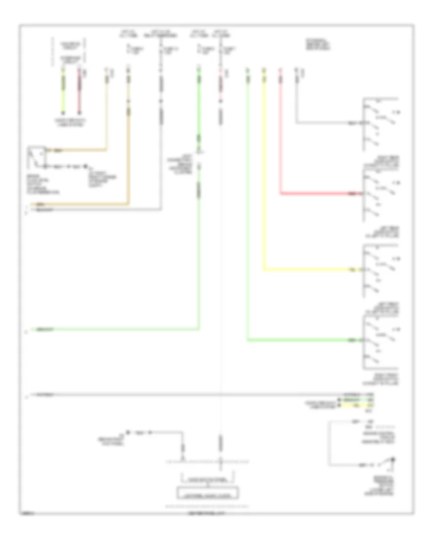
INSTRUMENT CLUSTER
Instrument Cluster Wiring Diagram, Evolution (1 of 2) for Mitsubishi Lancer ES 2008
 https://portal-diagnostov.com/license.html
Automotive Electricians Portal FZCO
Automotive Electricians Portal FZCO
https://portal-diagnostov.com/license.html
https://portal-diagnostov.com/license.html
Automotive Electricians Portal FZCO
Automotive Electricians Portal FZCO
List of elements for Instrument Cluster Wiring Diagram, Evolution (1 of 2) for Mitsubishi Lancer ES 2008:
- Abs ind
- Air conditioning, sound & interior lights systems
- Beam ind
- Brake ind
- C107
- Can transceiver circuit
- Combination meter
- Computer data lines system
- Cpu
- Cruise ind
- Driver's seat belt ind
- Fog ind
- Fuel level sensor
- Fuel level sensor (sub) (top of fuel tank)
- Fuel pump module (top of fuel tank)
- Fuel tank temperature sensor
- G18 (behind left kick panel)
- G22 (behind left rear quarterpanel)
- G4 (behind right kick panel)
- Generator malfunction light ind
- Illum
- Interface circuit
- Joint connector 3 (behind instrument cluster)
- Joint connector 5 (base of left "b" pillar)
- Lcd (abs, asc off, asc failure, asc active, brake, tarmac, gravel, snow, acd, ayc)
- Lcd (each door)
- Lcd (engine coolant temperature)
- Lcd (fuel warning, oil, brake)
- Lcd (generator malfunction light)
- Lcd (key reminder)
- Lcd (kos)
- Lcd (malfunction ind light) (service engine soon)
- Lcd (odo/trip, fuel gauge, temperature gauge, service reminder, outside temperature)
- Lcd (security)
- Lcd (shift position, normal, sport, s-sport)
- Lcd (tire pressure)
- Led drive circuit
- Left turn ind
- Malfunction ind light (service engine soon)
- Meter information switch
- Parking brake switch (under center console)
- Pnk
- Radio & cd player
- Rheostat
- Right turn ind
- Speedometer
- Srs ind
- Tachometer
- Tail ind
- Tone alarm
- Transmissions system
- Warning systems
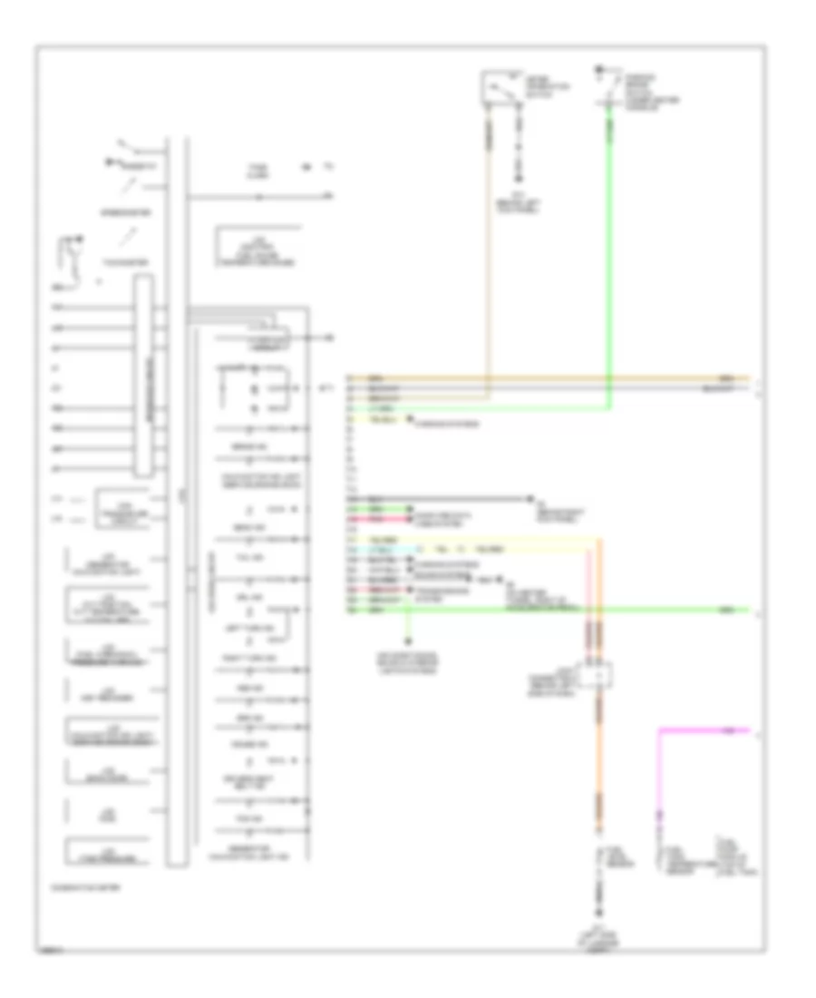
Instrument Cluster Wiring Diagram, Evolution (2 of 2) for Mitsubishi Lancer ES 2008
 https://portal-diagnostov.com/license.html
Automotive Electricians Portal FZCO
Automotive Electricians Portal FZCO
https://portal-diagnostov.com/license.html
https://portal-diagnostov.com/license.html
Automotive Electricians Portal FZCO
Automotive Electricians Portal FZCOList of elements for Instrument Cluster Wiring Diagram, Evolution (2 of 2) for Mitsubishi Lancer ES 2008:
- Audio switch panel
- B09
- B10
- Brake fluid level switch (on brake fluid reservoir)
- C301
- C312
- C313
- C317
- Can drive circuit
- Center panel unit
- Computer data lines system
- Engine control module (near relay box)
- Engine oil pressure switch (lower left side of engine)
- Etacs-ecu (behind left end of dash)
- Fuse 12 7.5a
- Fuse 7 15a
- Fuse 8 7.5a
- Fuse 9 15a
- G1 (at right front corner of engine compt)
- G4 (behind right kick panel)
- Hot at all times
- Hot w/ ig1 relay energized
- Interface circuit
- Joint connector 3 (behind instrument cluster)
- Lcd panel (audio, clock)
- Left front door switch (in left "b" pillar)
- Left rear door switch (in left "c" pillar)
- Red
- Right front door switch (in right "b" pillar)
- Right rear door switch (in right "c" pillar)
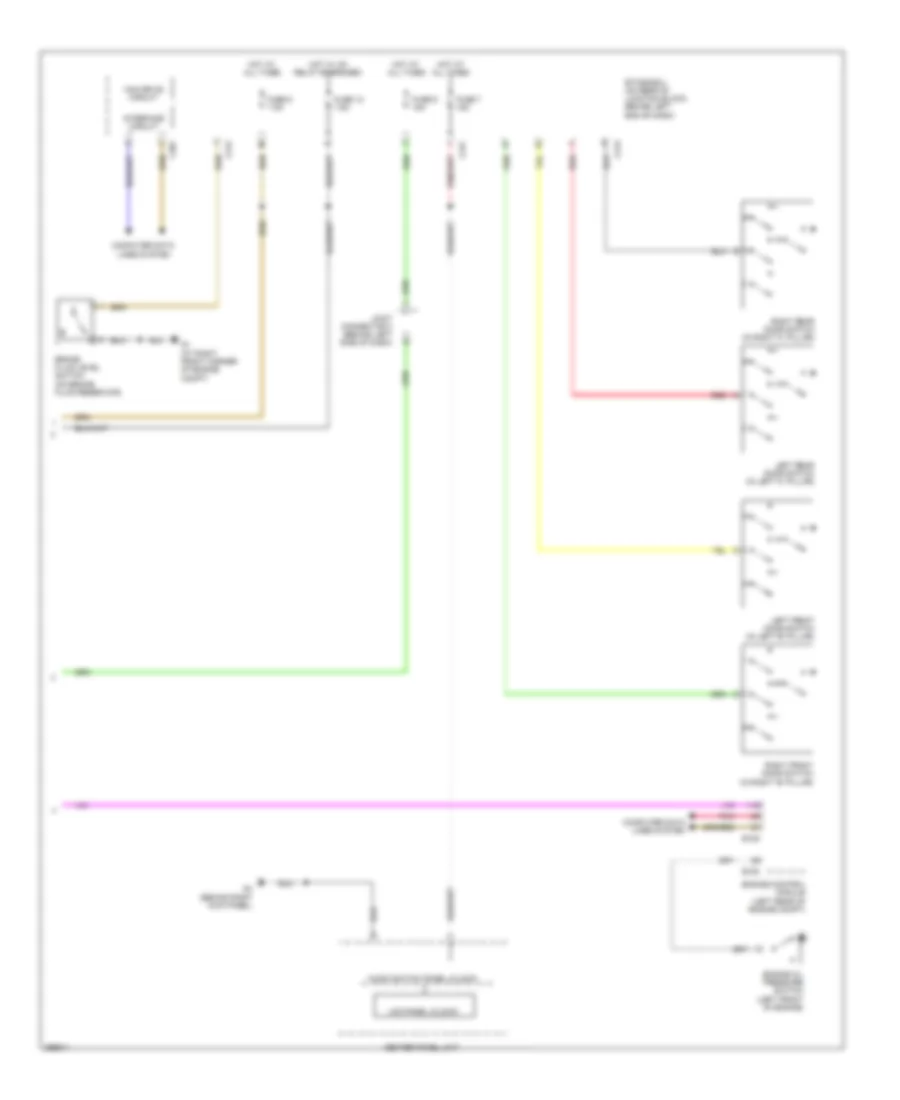
Instrument Cluster Wiring Diagram, Except Evolution (1 of 2) for Mitsubishi Lancer ES 2008
 https://portal-diagnostov.com/license.html
Automotive Electricians Portal FZCO
Automotive Electricians Portal FZCO
https://portal-diagnostov.com/license.html
https://portal-diagnostov.com/license.html
Automotive Electricians Portal FZCO
Automotive Electricians Portal FZCOList of elements for Instrument Cluster Wiring Diagram, Except Evolution (1 of 2) for Mitsubishi Lancer ES 2008:
- Abs ind
- Air conditioning, sound & interior lights systems
- Beam ind
- Brake ind
- Can transceiver circuit
- Combination meter
- Computer data lines system
- Cpu
- Cruise ind
- Driver's seat belt ind
- Drl ind
- Fog ind
- Fuel level sensor
- Fuel pump module (top of fuel tank)
- Fuel tank temperature sensor
- G11 (left side of luggage compt)
- G14 (behind left kick panel)
- G4 (behind right kick panel)
- G5 (on center tunnel, right of accelerator pedal)
- Generator malfunction light ind
- Illum
- Interface circuit
- Joint connector 5 (behind left side of dash)
- Lcd (cvt position, cvt temperature, cvt failure)
- Lcd (each door)
- Lcd (fuel warning/oil pressure warning)
- Lcd (generator malfunction light)
- Lcd (key reminder)
- Lcd (kos)
- Lcd (malfunction ind light) (service engine soon)
- Lcd (odo/trip, fuel gauge, temperature gauge)
- Lcd (tire pressure)
- Led drive circuit
- Left turn ind
- Malfunction ind light (service engine soon)
- Meter information switch
- Parking brake switch (under center console)
- Pnk
- Rheostat
- Right turn ind
- Sound systems
- Speedometer
- Srs ind
- Tachometer
- Tail ind
- Tone alarm
- Transmissions system
- Warning systems
Instrument Cluster Wiring Diagram, Except Evolution (2 of 2) for Mitsubishi Lancer ES 2008
 https://portal-diagnostov.com/license.html
Automotive Electricians Portal FZCO
Automotive Electricians Portal FZCO
https://portal-diagnostov.com/license.html
https://portal-diagnostov.com/license.html
Automotive Electricians Portal FZCO
Automotive Electricians Portal FZCOList of elements for Instrument Cluster Wiring Diagram, Except Evolution (2 of 2) for Mitsubishi Lancer ES 2008:
- Audio switch panel (clock)
- B108
- B109
- Brake fluid level switch (on brake fluid reservoir)
- C301
- C312
- C313
- C317
- Can drive circuit
- Center panel unit
- Computer data lines system
- Engine control module (left rear of engine compt)
- Engine oil pressure switch (left front of engine)
- Etacs-ecu (on rear of junction block, behind left end of dash)
- Fuse 12 7.5a
- Fuse 7 15a
- Fuse 8 7.5a
- Fuse 9 15a
- G1 (at right front corner of engine compt)
- G4 (behind right kick panel)
- Hot at all times
- Hot w/ ig1 relay energized
- Interface circuit
- Joint connector 3 (behind left side of dash)
- Lcd panel (clock)
- Left front door switch (in left "b" pillar)
- Left rear door switch (in left "c" pillar)
- Pnk
- Red
- Right front door switch (in right "b" pillar)
- Right rear door switch (in right "c" pillar)

 Čeština
 Dansk
Dansk Deutsch
 Ελληνικά
 English
 English
 Español
 Suomi
Suomi Français
 Français
 עברית
עברית Hrvatski
 Magyar
 Italiano
 日本語
日本語 한국어
한국어 Nederlands
 Polski
 Português
 Português
 Română
 Русский
 Slovenčina
 Slovenščina
 Svenska
 Türkçe
