SUPPLEMENTAL RESTRAINTS
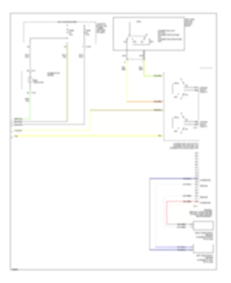
Supplemental Restraints Wiring Diagram, with Side Airbag (1 of 2) for Mitsubishi Eclipse Spyder GT 2005
 https://portal-diagnostov.com/license.html
Automotive Electricians Portal FZCO
Automotive Electricians Portal FZCO
https://portal-diagnostov.com/license.html
https://portal-diagnostov.com/license.html
Automotive Electricians Portal FZCO
Automotive Electricians Portal FZCO
List of elements for Supplemental Restraints Wiring Diagram, with Side Airbag (1 of 2) for Mitsubishi Eclipse Spyder GT 2005:
- (below left side of dash, behind junction block) g15
- (under lower center of dash, on right center reinforcement) g14
- Air bag drive circuit
- C-72
- Clock spring
- Connector lock switch (connector coupled: on) (connector uncoupled: off)
- Connector lock switch (connector coupled: on) connector uncoupled: off)
- Data
- Data link connector (dlc) (partial) (below left side of dash)
- Detection circuit
- Driver's side air bag module squib
- Ground
- Ignition
- J/c 1 (behind left kick panel)
- Nca
- Off
- Passenger's side air bag module squib
- Right side air bag module squib
- Srs-ecu (behind lower center of dash, near center reinforcement)
- Warning light
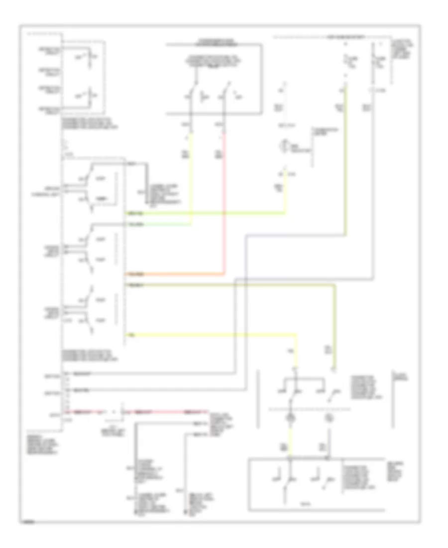
Supplemental Restraints Wiring Diagram, with Side Airbag (2 of 2) for Mitsubishi Eclipse Spyder GT 2005
 https://portal-diagnostov.com/license.html
Automotive Electricians Portal FZCO
Automotive Electricians Portal FZCO
https://portal-diagnostov.com/license.html
https://portal-diagnostov.com/license.html
Automotive Electricians Portal FZCO
Automotive Electricians Portal FZCOList of elements for Supplemental Restraints Wiring Diagram, with Side Airbag (2 of 2) for Mitsubishi Eclipse Spyder GT 2005:
- Air bag drive circuit
- C-108
- C-41
- C-42
- C-74
- Combination meter
- Connector lock switch (connector coupled: on) (connector uncoupled: off)
- Fuse 7.5a
- Ground
- Hot in on or start
- Interface
- Junction block (j/b) (under left end of dash)
- Left side air bag module squib
- Left side impact sensor (in base of left "b" pillar)
- Nca
- Off
- Right side impact sensor (in base of right "b" pillar)
- Srs indicator
- Srs-ecu (behind lower center of dash, near center reinforcement)
Supplemental Restraints Wiring Diagram, without Side Airbag for Mitsubishi Eclipse Spyder GT 2005
 https://portal-diagnostov.com/license.html
Automotive Electricians Portal FZCO
Automotive Electricians Portal FZCO
https://portal-diagnostov.com/license.html
https://portal-diagnostov.com/license.html
Automotive Electricians Portal FZCO
Automotive Electricians Portal FZCOList of elements for Supplemental Restraints Wiring Diagram, without Side Airbag for Mitsubishi Eclipse Spyder GT 2005:
- (below left side of dash)
- (below left side of dash, behind junction block) g15
- (connector coupled: on) (connector uncoupled: off) connector lock switch
- (in dash wiring harness, at breakout for srs-ecu) s211
- (under lower center of dash, on right center reinforcement) g14
- Air bag drive circuit
- C-108
- C-41
- C-42
- C-72
- Clock spring
- Combination meter
- Connector lock switch (connector coupled: on) (connector uncoupled: off)
- Data
- Data link connector (partial)
- Detection circuit
- Driver's side air bag module squib
- Fuse 7.5a
- Ground
- Hot in on or start
- Ignition
- J/c 1 (behind left kick panel)
- Junction block (j/b) (under left end of dash)
- Nca
- Off
- Passenger's side air bag module squib
- Srs indicator
- Srs-ecu (behind lower center of dash, near center reinforcement)
- Warning light

 Čeština
 Dansk
Dansk Deutsch
 Ελληνικά
 English
 English
 Español
 Suomi
Suomi Français
 Français
 עברית
עברית Hrvatski
 Magyar
 Italiano
 日本語
日本語 한국어
한국어 Nederlands
 Polski
 Português
 Português
 Română
 Русский
 Slovenčina
 Slovenščina
 Svenska
 Türkçe
