CRUISE CONTROL
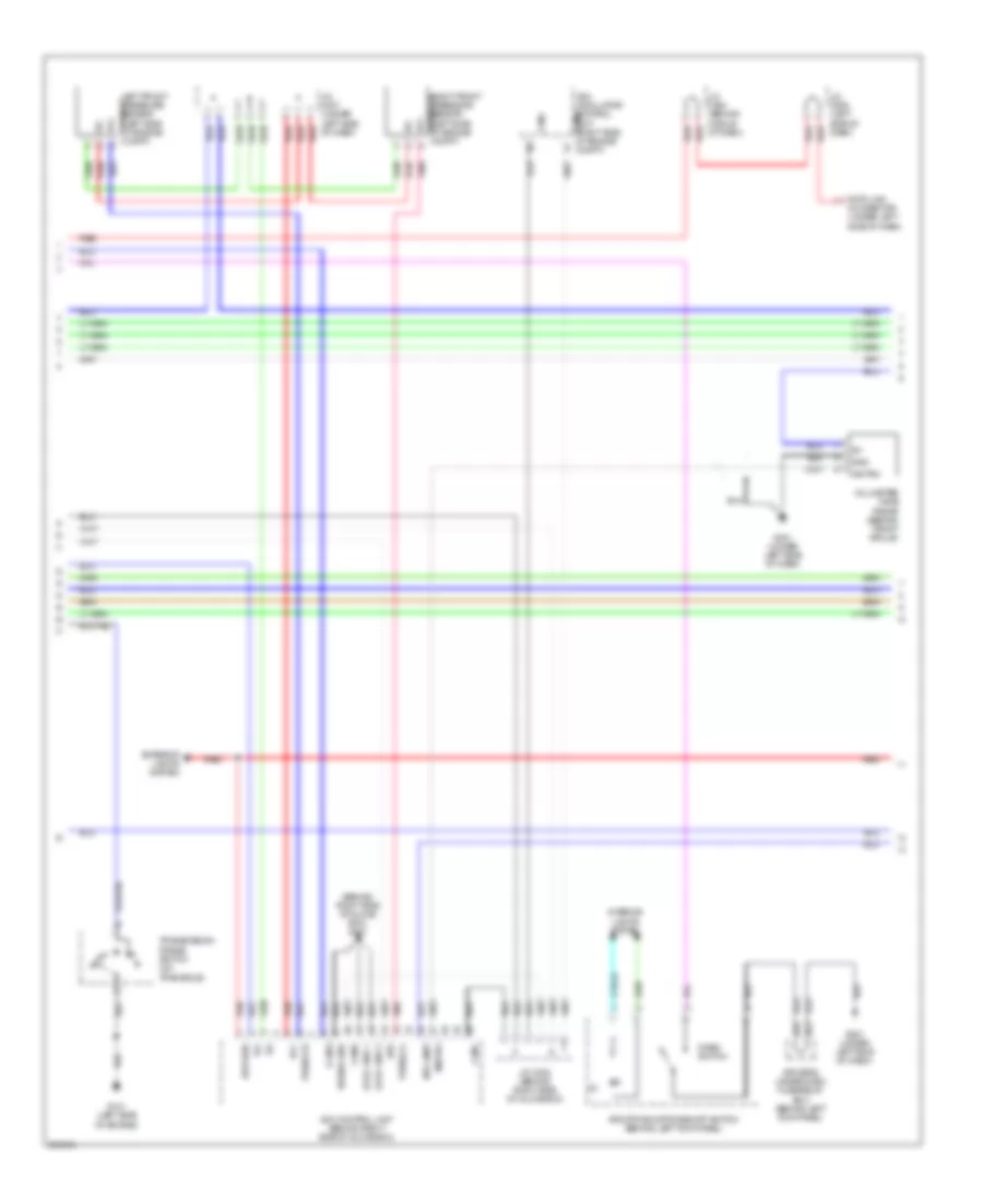
Cruise Control Wiring Diagram, with Technology Package (1 of 3) for Acura RL 2006
 https://portal-diagnostov.com/license.html
Automotive Electricians Portal FZCO
Automotive Electricians Portal FZCO
https://portal-diagnostov.com/license.html
https://portal-diagnostov.com/license.html
Automotive Electricians Portal FZCO
Automotive Electricians Portal FZCO
List of elements for Cruise Control Wiring Diagram, with Technology Package (1 of 3) for Acura RL 2006:
- (under right side of dash) j/c c525
- 10v regulator
- A14
- A15
- A25
- A26
- Acc indicator
- App sensor (under left side of dash)
- Apsa
- Apsb
- Area controller
- Atp-fwd
- B10
- B15
- B16
- B19
- B22
- B23
- Beeper
- Bksw
- Bkswnc
- C19
- Canh
- Canl
- Circuit
- Circuit drive
- Circuit fail-safe
- Cms indicator
- Controller area network controller
- Dbw m+
- Dbw m-
- Dbwrly
- Dimming circuit cruise control
- Drive circuit warning
- Driver's under-dash fuse/relay box (behind left kick panel)
- E12
- E15
- E26
- Fast
- Fuse 21 10a
- Fuse 29 10a
- Fuse 7 10a
- G101 (left side of engine)
- G501 (under left side of dash)
- Gauge control module
- Green
- Hot at all times
- Hot in on or start
- J/c c508 (left side of dash)
- J/c c509 (left side of dash)
- J/c c512 (left side of dash)
- J/c c522 (behind middle of dash)
- J/c c525 (under right side of dash)
- Mrly
- Network transceiver
- Orange
- Output shaft (countershaft) speed sensor (in transmission housing)
- Passenger's under-dash fuse/relay box (behind right kick panel)
- Pcm (under middle of dash)
- Pg2
- Pnk
- Red
- Sedf
- Sefd
- Sg3
- Sg4
- Thl1
- Thl2
- Throttle actuator control module (behind right kick panel)
- Tp sensor/throttle actuator (on throttle body)
- Turning-on compulsory
- Vcc
- Vcc3
- Vcc4
- X20
- X34
- X35
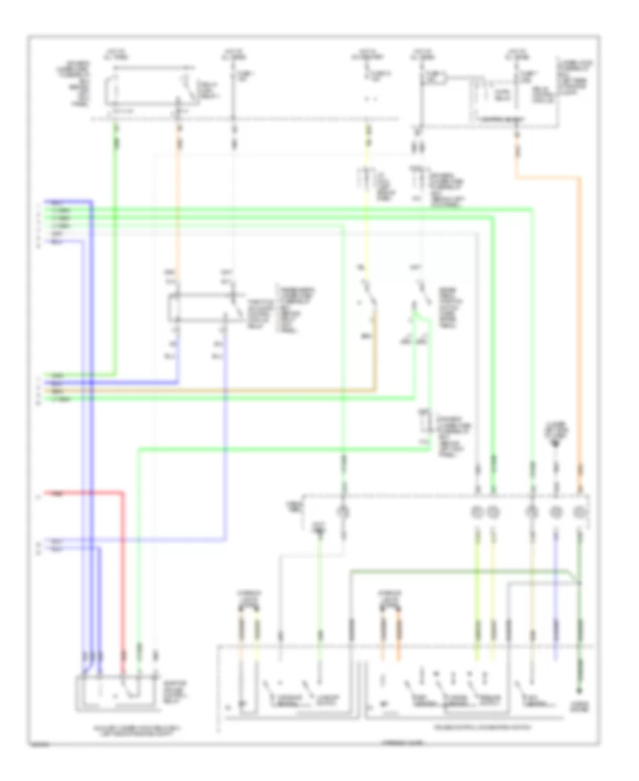
Cruise Control Wiring Diagram, with Technology Package (2 of 3) for Acura RL 2006
 https://portal-diagnostov.com/license.html
Automotive Electricians Portal FZCO
Automotive Electricians Portal FZCO
https://portal-diagnostov.com/license.html
https://portal-diagnostov.com/license.html
Automotive Electricians Portal FZCO
Automotive Electricians Portal FZCOList of elements for Cruise Control Wiring Diagram, with Technology Package (2 of 3) for Acura RL 2006:
- (2)
- (behind right side of glove box) g401
- Acc control unit (behind right side of glove box)
- Afs off/vsa off/cmbs off switch (behind left kick panel)
- Brk diag
- Brk lamp
- Canh
- Canl
- Cmbs switch
- Compt)
- Data link connector (under left side of dash)
- Driver's under-dash fuse/relay box (behind left kick panel)
- Exterior lights system
- G101 (left side of engine)
- G401 (under left side of dash)
- G501 (under left side of dash)
- Gnd
- Ig1
- Interior lights system
- J/c c202 (behind right side of glove box)
- J/c c307 (under left side of dash)
- J/c c508 (left side of dash)
- J/c c524 (behind middle of dash)
- K-line
- Left front pressure sensor (left side of engine compt) press fl
- Logic gnd 1
- Logic gnd 2
- Millimeter wave radar (behind front grille)
- Mr/trx
- N21
- N37
- Pnk
- Power gnd
- Press fl
- Press fr
- Red
- Right front pressure sensor (left side of engine compt) press fr
- Transmission range switch (on transaxle)
- Vbu
- Vcc
- Vsa modulator- control unit (right side of engine canh
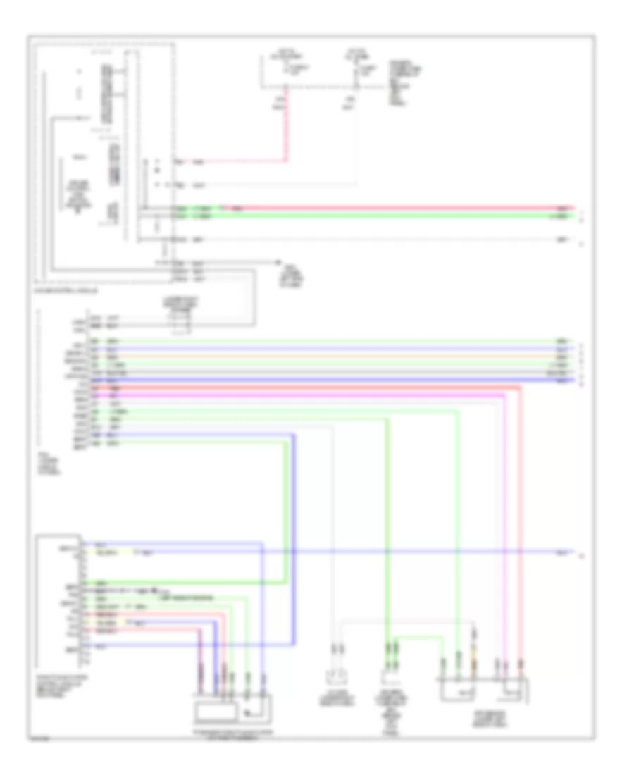
Cruise Control Wiring Diagram, with Technology Package (3 of 3) for Acura RL 2006
 https://portal-diagnostov.com/license.html
Automotive Electricians Portal FZCO
Automotive Electricians Portal FZCO
https://portal-diagnostov.com/license.html
https://portal-diagnostov.com/license.html
Automotive Electricians Portal FZCO
Automotive Electricians Portal FZCOList of elements for Cruise Control Wiring Diagram, with Technology Package (3 of 3) for Acura RL 2006:
- (2)
- (3)
- (not used)
- (under left side of dash) g501
- Acc switch
- Adaptive cruise control relay
- Auxiliary under-hood relay box (left side of engine compt)
- B13
- B15
- Brake pedal position switch (near brake pedal)
- C11
- C12
- C13
- C14
- Cable reel
- Cancel switch
- Control block
- Cruise control combination switch
- D13
- D14
- Distance switch
- Driver's under-dash fuse/relay box (behind left kick panel)
- E11
- E14
- F12
- Fuse 1 15a
- Fuse 13 15a
- Fuse 18 15a
- Fuse 7 7.5a
- Horn relay
- Horns system
- Hot at all times
- Hot in on or start
- Interior lights system
- J/c c510 (left side of dash)
- Lkas off switch
- N26
- N29
- Passenger's under-dash fuse/relay box (behind right kick panel)
- Pgm-fi main relay 1
- Red
- Relay control module
- Resume switch
- Set switch
- Steering wheel
- Throttle actuator control module relay
- Under-hood fuse/relay box (left rear of engine compt)
- X10
- X23
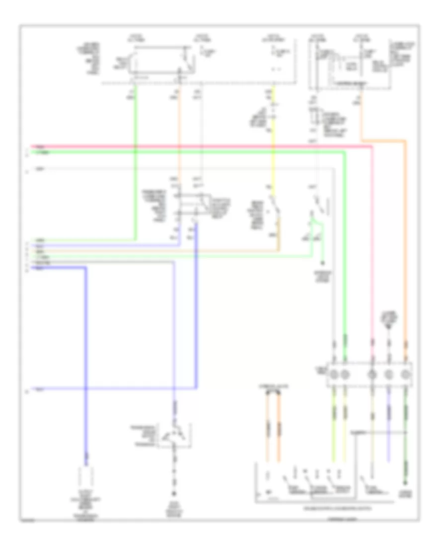
Cruise Control Wiring Diagram, without Technology Package (1 of 2) for Acura RL 2006
 https://portal-diagnostov.com/license.html
Automotive Electricians Portal FZCO
Automotive Electricians Portal FZCO
https://portal-diagnostov.com/license.html
https://portal-diagnostov.com/license.html
Automotive Electricians Portal FZCO
Automotive Electricians Portal FZCOList of elements for Cruise Control Wiring Diagram, without Technology Package (1 of 2) for Acura RL 2006:
- (under right side of dash) j/c c525
- A14
- A15
- A25
- A26
- App sensor (under left side of dash)
- Apsa
- Apsb
- Atp-fwd
- B15
- B16
- B19
- B22
- Bksw
- Bkswnc
- C19
- Canh
- Canl
- Cruise control main switch indicator
- Dbw m+
- Dbw m-
- Dbwrly
- Dimming circuit cruise control
- Drive circuit
- Driver's under-dash fuse/relay box (behind left kick panel)
- E12
- E15
- E26
- Fuse 21 10a
- Fuse 7 10a
- G101 (left side of engine)
- G501 (under left side of dash)
- Gauge control module
- Hot at all times
- Hot in on or start
- J/c c525 (under right side of dash)
- Mrly
- Network transceiver fast controller area
- Pcm (under middle of dash)
- Pg2
- Pnk
- Red
- Sedf
- Sefd
- Sg3
- Sg4
- Thl1
- Thl2
- Throttle actuator control module (behind right kick panel)
- Tp sensor/throttle actuator (on throttle body)
- Vcc
- Vcc3
- Vcc4
- X34
- X35
Cruise Control Wiring Diagram, without Technology Package (2 of 2) for Acura RL 2006
 https://portal-diagnostov.com/license.html
Automotive Electricians Portal FZCO
Automotive Electricians Portal FZCO
https://portal-diagnostov.com/license.html
https://portal-diagnostov.com/license.html
Automotive Electricians Portal FZCO
Automotive Electricians Portal FZCOList of elements for Cruise Control Wiring Diagram, without Technology Package (2 of 2) for Acura RL 2006:
- (3)
- (under left side of dash) g501
- B15
- Brake pedal position switch (near brake pedal)
- C11
- C12
- C13
- C14
- Cable reel
- Cancel switch
- Control block
- Cruise control combination switch
- D13
- D14
- Driver's under-dash fuse/relay box (behind left kick panel)
- E11
- E14
- Exterior lights system
- Fuse 1 15a
- Fuse 13 20a
- Fuse 18 15a
- Fuse 7 7.5a
- G102 (right front of engine)
- Horn relay
- Horns system
- Hot at all times
- Hot in on or start
- Interior lights system
- J/c c507 (behind left side of dash)
- Main switch
- N29
- Output shaft (countershaft) speed sensor (in transmission housing)
- Passenger's under-dash fuse/relay box (behind right kick panel)
- Pgm-fi main relay 1
- Pnk
- Relay control module
- Resume switch
- Set switch
- Steering wheel
- Throttle actuator control module relay
- Transmission range switch (on transaxle)
- Under-hood fuse/relay box (left rear of engine compt)
- X10
- X23

 Čeština
 Dansk
Dansk Deutsch
 Ελληνικά
 English
 English
 Español
 Suomi
Suomi Français
 Français
 עברית
עברית Hrvatski
 Magyar
 Italiano
 日本語
日本語 한국어
한국어 Nederlands
 Polski
 Português
 Português
 Română
 Русский
 Slovenčina
 Slovenščina
 Svenska
 Türkçe
