POWER DISTRIBUTION
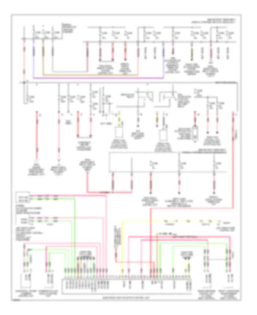
Power Distribution Wiring Diagram (1 of 7) for Mercedes-Benz S550 4Matic 2014
 https://portal-diagnostov.com/license.html
Automotive Electricians Portal FZCO
Automotive Electricians Portal FZCO
https://portal-diagnostov.com/license.html
https://portal-diagnostov.com/license.html
Automotive Electricians Portal FZCO
Automotive Electricians Portal FZCO
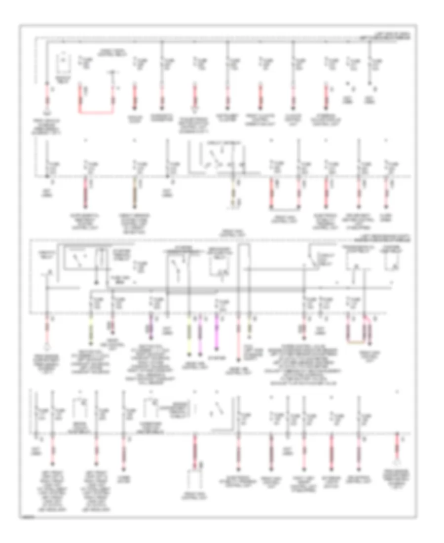
List of elements for Power Distribution Wiring Diagram (1 of 7) for Mercedes-Benz S550 4Matic 2014:
- (diagram 3 of 7) relay module from rear fuse &
- (not used)
- (right rear engine compt) engine compartment prefuse box
- (upper right footwell) vehicle interior prefuse box
- 115v ac1
- 115v ac2
- 115v socket
- 230v ac1
- 230v ac2
- 230v socket
- 7.5a
- Ac housing
- Alternator
- Battery sensor
- Dc/ac converter control unit (w/ 115v socket) (right rear of luggage compt)
- Dc/ac converter control unit (w/ 230v socket) (right rear of luggage compt)
- Electrical power steering control unit
- Electronic stability program control unit
- Emergency start system relay
- Enable
- Fan motor (early production)
- Fan motor (late production)
- From rear fuse & relay module (diagram 3 of 7)
- From rear fuse & relay module (diagram 5 of 7)
- From rear fuse & relay module p (diagram 5 of 7)
- Front sam control unit
- Fuse 100a
- Fuse 125a
- Fuse 150a
- Fuse 40a
- Fuse 500a
- Fuse 60a
- Left terminal 30 terminal block (w/o backup)
- Mr1
- Mr2
- Mr3
- Mr4
- Mr5
- Nca
- On-board electrical system battery
- Pyrotechnical separator
- Quiescent current cutout relay
- Rba
- Red
- Right rear hydraulic window lifter fuse block (upper front of right rear door)
- Right terminal 30 terminal block
- Special protection vehicle additional battery
- Starter
- To engine fuse & relay module (diagram 2 of 7)
- To instrument panel fuse box (diagram 7 of 7)
- To left fuse & relay module (diagram 2 of 7)
- To rear fuse & relay module (diagram 4 of 7)
- To rear prefuse box (diagram 6 of 7)
- W54 (right side of luggage compt)
- Wndl sig
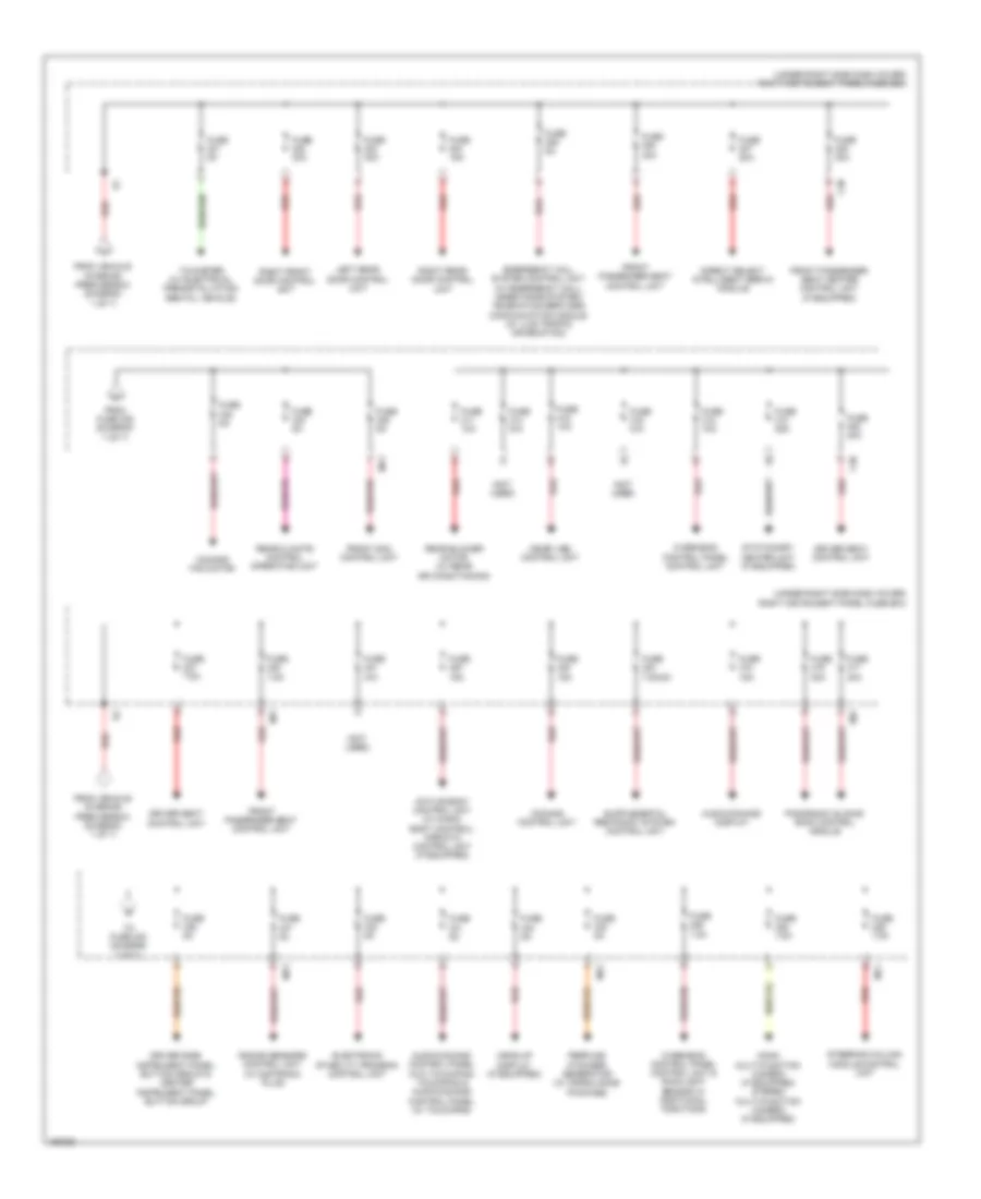
Power Distribution Wiring Diagram (2 of 7) for Mercedes-Benz S550 4Matic 2014
 https://portal-diagnostov.com/license.html
Automotive Electricians Portal FZCO
Automotive Electricians Portal FZCO
https://portal-diagnostov.com/license.html
https://portal-diagnostov.com/license.html
Automotive Electricians Portal FZCO
Automotive Electricians Portal FZCOList of elements for Power Distribution Wiring Diagram (2 of 7) for Mercedes-Benz S550 4Matic 2014:
- (+)
- (left end of dash) left fuse & relay module
- (left rear engine compt) engine fuse & relay module
- (not used)
- Airmatic relay
- Alarm siren
- Analog clock
- Backup relay
- Brake vacuum pump relay
- C200
- C201
- C202
- C203
- C213
- C218
- C219
- C220
- Circuit 15r relay
- Circuit 87m relay
- Climate control unit
- Diagnostic connector
- Driver seat heater control unit (if equipped)
- Drivetrain control unit
- Electronic stability program control unit
- Engine compartment terminal 15 relay
- Exterior lights switch
- F85
- Fanfare horn relay
- From engine compartment prefuse box (diagram 1 of 7)
- From vehicle interior prefuse box (diagram 1 of 7)
- Front climate control operating unit
- Front sam control unit
- Fuse 10a
- Fuse 129a 30a
- Fuse 15a
- Fuse 20a
- Fuse 25a
- Fuse 30a
- Fuse 40a
- Fuse 5a
- Fuse 7.5a
- Fuse n/a
- Ignition coil cylinders 1, 4, 7 & 6, right exhaust camshaft solenoid, right intake camshaft solenoid, right intake camshaft hall sensor & right exhaust camshaft hall sensor
- Ignition coil cylinders 2, 3, 8 & 5, left exhaust camshaft solenoid, left intake camshaft solenoid
- Instrument cluster
- Left front lamp unit & right front lamp unit (w/ intelligent light system) left front lamp unit (w/ static led headlamp)
- Left front lamp unit & right front lamp unit (w/ intelligent light system) right front lamp unit (w/ static led headlamp)
- Magic vision control relay
- Me-sfi (me) control unit
- Mr2
- Night view assist control unit (if equipped)
- Pnk/red
- Purge control valve, engine diagnosis radiator sensor, left oxygen sensor downstream of catalytic converter, left oxygen sensor upstream of catalytic converter, coolant thermostat heating element, activated charcoal filter shutoff valve & exhaust flap switchover valve
- Rba
- Red
- Secondary air injection relay
- Starter
- Starter circuit 50 relay
- Starter terminal 15 relay
- Steering column module control unit
- To electronic ignition switch control unit (diagram 6 of 7)
- Transmission oil pump relay
- W3/2 (left side of engine compt)
- Weight sensing system (wss) control unit (w/ weight detection)
- Wiper motor
- Wiper park position heater relay
Power Distribution Wiring Diagram (3 of 7) for Mercedes-Benz S550 4Matic 2014
 https://portal-diagnostov.com/license.html
Automotive Electricians Portal FZCO
Automotive Electricians Portal FZCO
https://portal-diagnostov.com/license.html
https://portal-diagnostov.com/license.html
Automotive Electricians Portal FZCO
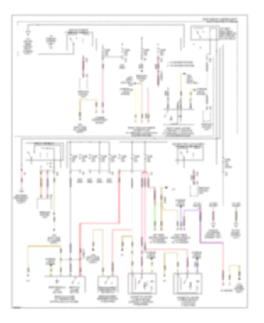
Automotive Electricians Portal FZCOList of elements for Power Distribution Wiring Diagram (3 of 7) for Mercedes-Benz S550 4Matic 2014:
- (left front footwell) w34
- (not used)
- (right side of luggage compt) rear fuse & relay module
- 12v socket
- 1st seat row/trunk refrigerator box & power outlet relay
- 2nd seat row cup holder & power outlet relay
- Cigarette lighter w/ rear ashtray illumination (if equipped)
- Cigarette lighter w/ rear center console illumination (if equipped)
- Circuit 15r relay
- From rear prefuse box (diagram 6 of 7)
- Front cigar lighter w/ ashtray illumination (w/ ambiance illumination & w/o smoker package)
- Front vehicle interior power outlet (w/ ambiance illumination & smoker package)
- Fuse 10a
- Fuse 15a
- Fuse 15a (or 5a)
- Fuse 5a
- Fuse n/a
- Interior lights system
- Left rear center console 12v socket (w/ 12v socket)
- Luggage compartment socket
- Nca
- Pnk/red
- Rear backrest refrigerator box (if equipped)
- Rear backrest refrigerator box switch
- Rear cup holder (w/ temperature controlled cup holder)
- Rear cup holder button
- Rear residual heat ind lamp
- Rear sam control unit
- Red
- Right rear center console 12v socket (w/ 12v socket)
- S12
- S13
- S18
- To 115v socket (diagram 1 of 7)
- To dc/ac converter control unit (diagram 1 of 7)
- To fuse 454 (diagram 4 of 7)
- To heated rear window relay (diagram 4 of 7)
- Vehicle interior terminal 15 relay
- W/ 115v socket
- W/ 12v socket
- W/ 230v socket
- W/ smoker package
- W/o smoker package
- W18 (under driver's seat)
- W34 (left front footwell)
- W54 (right side of luggage compt)
- X138/6-c1
- X18/35-c4
- X58/46
Power Distribution Wiring Diagram (4 of 7) for Mercedes-Benz S550 4Matic 2014
 https://portal-diagnostov.com/license.html
Automotive Electricians Portal FZCO
Automotive Electricians Portal FZCO
https://portal-diagnostov.com/license.html
https://portal-diagnostov.com/license.html
Automotive Electricians Portal FZCO
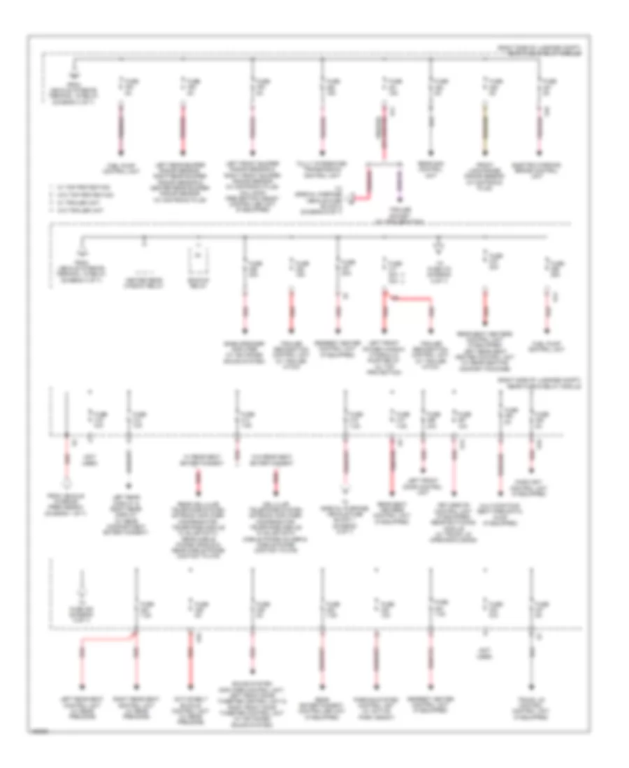
Automotive Electricians Portal FZCOList of elements for Power Distribution Wiring Diagram (4 of 7) for Mercedes-Benz S550 4Matic 2014:
- (not used)
- (right side of luggage compt) rear fuse & relay module
- Active belt buckle control unit (w/ rear pre-safe)
- Armrest heater control unit (if equipped)
- Backup relay
- Bass speaker amplifier (w/ advanced sound system)
- Electric parking brake control unit
- From vehicle interior prefuse box (diagram 1 of 7)
- From vehicle interior terminal 15 relay (diagram 3 of 7)
- Front long range radar sensor (w/ distronic plus)
- Fuel pump control unit
- Fully integrated transmission control unit
- Fuse 10a
- Fuse 15a
- Fuse 20a
- Fuse 20a 30a
- Fuse 25a
- Fuse 30a
- Fuse 5a
- Fuse 7.5a
- Fuse n/a
- Heated rear window relay
- Keyless go control unit (if equipped) rear switching module (w/ trunk lid opening/closing)
- Left front bumper radar sensor & right front bumper radar sensor (w/ distronic plus) collision prevention assist controller unit (if equipped)
- Left front door control unit
- Left front power window hydraulic pump relay (w/ top protection)
- Left rear bumper radar sensor, right rear bumper radar sensor & center rear bumper radar sensor (w/ distronic plus)
- Left rear display & right rear display (w/ rear compartment entertainment)
- Left rear seat control unit (w/ rear pre-safe)
- Magic sky control unit (if equipped)
- Multicontour seat pneumatic pump (if equipped)
- Parking system control unit (w/ active park assist)
- Pnk/red
- Rear entertainment controller unit (if equipped)
- Rear sam control unit
- Rear seat heaters control unit (if equipped)
- Rear seat heaters control unit (if equipped) left rear seat heater control unit (w/ rear seating comfort package)
- Red
- Red/pnk
- Right rear seat control unit (w/ rear pre-safe)
- S11
- S13
- S14
- S16
- Sound system amplifier control unit, left front door tweeter control unit & right front door tweeter control unit (w/ advanced sound system)
- T0 special purpose vehicle fuse block 1 (diagram 6 of 7)
- To fuse 472 (diagram 5 of 7)
- To fuse 483 (diagram 5 of 7)
- To special purpose vehicle fuse block 2 (diagram 6 of 7)
- Trailer recognition control unit (w/ trailer hitch)
- Trailer socket (w/ trailer hitch)
- Trunk lid control control unit (if equipped)
- W/ rear seat entertainment
- W/ top protection
- W/ trailer unit
- W/o rear seat entertainment
- W/o top protection
- W/o trailer unit
Power Distribution Wiring Diagram (5 of 7) for Mercedes-Benz S550 4Matic 2014
 https://portal-diagnostov.com/license.html
Automotive Electricians Portal FZCO
Automotive Electricians Portal FZCO
https://portal-diagnostov.com/license.html
https://portal-diagnostov.com/license.html
Automotive Electricians Portal FZCO
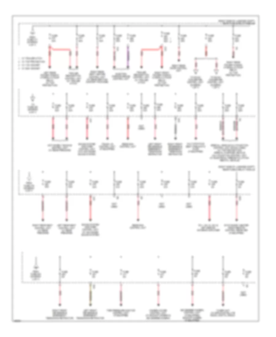
Automotive Electricians Portal FZCOList of elements for Power Distribution Wiring Diagram (5 of 7) for Mercedes-Benz S550 4Matic 2014:
- (not used)
- (right side of luggage compt) rear fuse & relay module
- 360 degree camera control unit (if equipped) backup camera (if equipped)
- Active belt buckle control unit (w/ rear pre-safe)
- Camera cover control unit (w/ backup camera & 360 degree camera)
- Electric parking brake control unit
- Fm 1, am, cl (zv) & keyless go antenna amplifier
- From fuse 417 (diagram 4 of 7)
- From fuse 479 (diagram 5 of 7)
- From fuse 484 (diagram 4 of 7)
- Fuse 20a
- Fuse 20a 30a
- Fuse 25a
- Fuse 30a
- Fuse 40a
- Fuse 5a
- Fuse n/a
- Left front reversible emergency tensioning retractor
- Left rear power window hydraulic pump relay (w/ top protection)
- Left rear seat control unit (w/ rear pre-safe)
- Multicontour seat pneumatic pump (if equipped)
- Rear sam control unit
- Red
- Right front power window hydraulic pump relay (w/ top protection)
- Right front reversible emergency tensioning retractor
- Right rear door control unit
- Right rear power window hydraulic pump relay (w/ top protection)
- Right rear seat control unit (w/ rear pre-safe)
- Right rear seat heater control unit (w/ rear seating comfort package)
- S10
- S13
- S14
- S15
- S16
- S17
- Sound system amplifier control unit (w/ advanced sound system)
- Sound system amplifier control unit (w/o advanced sound system)
- Special vehicle multifunction control unit (svmcu (mss)) (w/ top protection) special purpose vehicle multifunction control unit (w/ electrical preinstallation/ rental vehicle)
- Stationary heater radio remote control receiver (if equipped)
- Tire pressure monitor control unit (if equipped)
- To dc/ac converter control unit (diagram 1 of 7)
- To fuse 480 (diagram 5 of 7)
- Trailer recognition control unit (w/ trailer hitch)
- Trunk lid control unit (if equipped)
- Tuner unit (w/ sirius satellite radio, digital radio)
- W/ 115v socket
- W/ 230v socket
- W/ top protection
- W/ trailer hitch
Power Distribution Wiring Diagram (6 of 7) for Mercedes-Benz S550 4Matic 2014
 https://portal-diagnostov.com/license.html
Automotive Electricians Portal FZCO
Automotive Electricians Portal FZCO
https://portal-diagnostov.com/license.html
https://portal-diagnostov.com/license.html
Automotive Electricians Portal FZCO
Automotive Electricians Portal FZCOList of elements for Power Distribution Wiring Diagram (6 of 7) for Mercedes-Benz S550 4Matic 2014:
- (behind right rear seat) special purpose vehicle fuse block 1
- (behind right rear seat) special purpose vehicle fuse block 2
- (diagram 2 of 7) relay module from left fuse &
- (not used)
- 30b
- 30z
- Can-b h
- Can-b l
- Can-d h
- Can-d l
- Can-hmi h
- Can-hmi l
- Can-per h
- Can-per l
- Computer data lines system
- Decoupling relay
- Eco start/ stop function additional battery (if equipped)
- Eco start/stop function additional battery relay
- Electrical power steering control unit
- Electronic ignition switch control unit
- Fire extinguishing system & emergency fresh air system control unit
- Fr a bm
- Fr a bp
- Fr a1 bm
- Fr a1 bp
- Fr a1bm
- Fr a1bp
- Fr bm
- Fr bm1
- Fr bp
- Fr bp1
- Fr1 bm0
- Fr1 bp0
- Fr2 bm1
- Fr2 bp1
- Fr3 bm2
- Fr3 bp2
- Fr4 bm3
- Fr4 bp3
- Fr6 bm5
- Fr6 bp5
- Fr7 bm6
- Fr7 bp6
- From engine compartment prefuse box (diagram 1 of 7)
- From rear fuse & relay module (diagram 4 of 7)
- Front fire extinguishing system temperature sensor
- Front long-range radar sensor (w/ magic body control)
- Front sam control unit (w/ eco start/ stop function)
- Fuse 10a
- Fuse 125a
- Fuse 150a
- Fuse 15a
- Fuse 200a
- Fuse 30a
- Fuse 3a
- Fuse 5a
- Fuse 7.5a
- Fuse n/a
- I10
- Left front door control unit
- Left front door control unit (w/ magic body control) airmatic control unit (if equipped)
- Pas (gas) & special signal system control unit
- Pnk
- Pnk/red
- Radar sensors control unit (w/ magic body control)
- Rba
- Rear prefuse box
- Red
- Sig df
- Special protection vehicles fuse box
- Special signal system operating unit
- Steering column module control unit
- Stereo multi-function camera (w/ driver assistance package)
- To rear fuse & relay module (diagram 3 of 7)
- Vent flaps close relay, vent flaps open relay & irritant gas sensor
- W34 (left front footwell)
- W54 (right side of luggage compt)
- Windshield heater control unit (if equipped)
- X18-c1
- X18-c2
- X18/28-c1
- X18/35-c1
- X18/35-c4
- X35/1-c1
Power Distribution Wiring Diagram (7 of 7) for Mercedes-Benz S550 4Matic 2014
 https://portal-diagnostov.com/license.html
Automotive Electricians Portal FZCO
Automotive Electricians Portal FZCO
https://portal-diagnostov.com/license.html
https://portal-diagnostov.com/license.html
Automotive Electricians Portal FZCO
Automotive Electricians Portal FZCOList of elements for Power Distribution Wiring Diagram (7 of 7) for Mercedes-Benz S550 4Matic 2014:
- (not used)
- (under right side dash cover) right instrument panel fuse box
- 30g
- Active body control unit (w/ magic body control) airmatic control unit (if equipped)
- Audio/comand control panel (w/o touchpad) touchpad & audio/comand control panel (w/ touchpad)
- Audio/comand display
- C30
- Comand control unit
- Comand fan motor
- Direct select intelligent servo module
- Driver seat control unit
- Driver side instrument panel button group & center instrument panel button group
- Electronic stability program control unit
- Emergency call system control unit (w/ emergency call/ assistance system) telematics services communication module (w/ live traffic information)
- From fuse 339 (diagram 7 of 7)
- From vehicle interior prefuse box (diagram 1 of 7)
- Front passenger seat control unit
- Front passenger seat heater control unit (if equipped)
- Front sam control unit
- Fuse 10a
- Fuse 15a
- Fuse 20a
- Fuse 25a
- Fuse 30a
- Fuse 5a
- Fuse 7.5a
- Fuse 7.5a/5a
- Fuse n/a
- Head-up display (if equipped)
- Left rear door control unit
- Me-sfi (me) control unit
- Mf1
- Mf2
- Mf3
- Mfi
- Mono multi-function camera (if equipped) stereo multi-function camera (if equipped)
- Overhead control panel control unit
- Overhead control panel control unit & rain/light sensor w/ additional functions
- Panoramic sliding roof control module
- Perfume atomizer generator (w/ air balance package)
- Radar sensors control unit (w/ distronic plus)
- Rear blower motor (w/ rear air conditioning)
- Rear climate control operating unit
- Red
- Red/pnk
- Right front door control unit
- Right rear door control unit
- Stationary heater unit (if equipped)
- Steering column module control unit
- Taximeter (w/ electrical preinstallation/ rental vehicle)
- To fuse 338 (diagram 7 of 7)

 Čeština
 Dansk
Dansk Deutsch
 Ελληνικά
 English
 English
 Español
 Suomi
Suomi Français
 Français
 עברית
עברית Hrvatski
 Magyar
 Italiano
 日本語
日本語 한국어
한국어 Nederlands
 Polski
 Português
 Português
 Română
 Русский
 Slovenčina
 Slovenščina
 Svenska
 Türkçe
