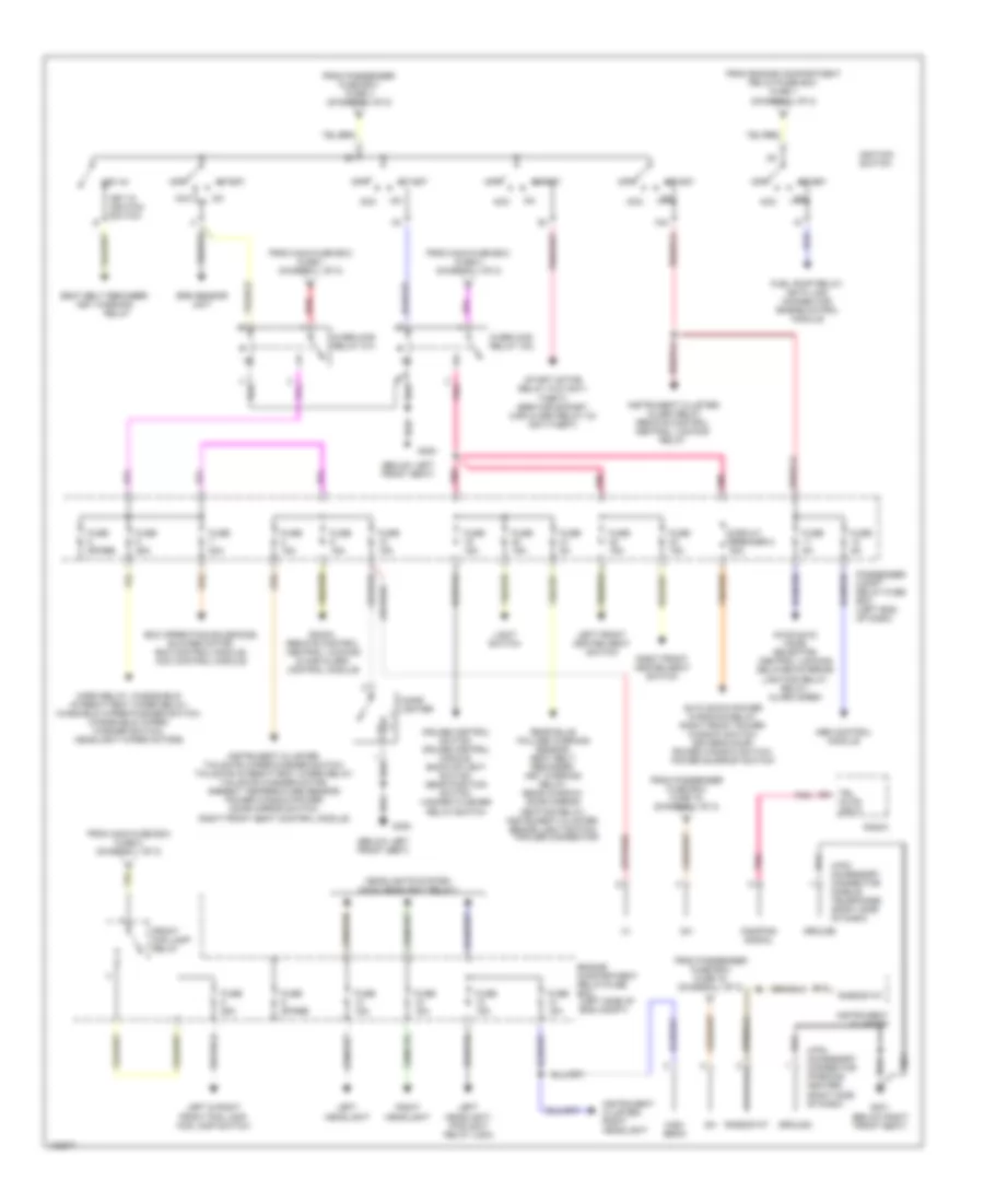
POWER DISTRIBUTION
Power Distribution Wiring Diagram (1 of 2) for Volvo V90 1998
 https://portal-diagnostov.com/license.html
Automotive Electricians Portal FZCO
Automotive Electricians Portal FZCO
https://portal-diagnostov.com/license.html
https://portal-diagnostov.com/license.html
Automotive Electricians Portal FZCO
Automotive Electricians Portal FZCO
List of elements for Power Distribution Wiring Diagram (1 of 2) for Volvo V90 1998:
- Abs modulator unit
- Accessory spot light connector
- Automatic climate control a/c relay
- Battery
- Car alarm relay, alarm siren, data link connector central locking delayed/interior lighting relay,
- Central locking delayed/interior lighting relay, 2-stage central locking driver's door relay
- Circuit breaker 30a
- Engine compartment relay/fuse box (left side of eng compt)
- Engine control module, mass air flow sensor, idle air control (iac) valve, injectors
- Engine control module, transmission control module
- Engine cooling fan relay
- Evap valve, air pump relay, auxiliary air system solenoids, front & rear oxygen sensors
- Fuel pump relay
- Fuel system main relay
- Fuse 10a
- Fuse 15a
- Fuse 20a
- Fuse 25a
- Fuse 50a
- Fuse 5a
- Fuse n/a
- Generator
- Glove lighting switch, central locking delayed/interior lighting relay, instrument cluster, dome light, trunk light, cargo compartment roof light, door switches, door open warning lights, entry lighting, vanity mirror lights, glass breakage sensor
- Hazard flasher relay/switch, car alarm relay, central locking delayed/interior lighting relay,
- Headlights system (light switch)
- Horn relay
- Ignition coil relay
- Left front park/turn lamp, foglight relay, rear bulb failure warning sensor, trailer connector, license plate light
- Left seat control module (memory)
- Light switch, brake light switch
- Main fuse box
- Main headlight relay/bulb failure warning sensor
- Marker/ parking light relay
- Passenger compt fuse box (left end of dash)
- Pnk
- Radio, cd-changer, booster amplifier
- Rear foglight switch
- Rear window/ door mirror heating relay
- Red
- Right front park/turn lamp, rear bulb failure warning sensor
- Start motor relay, air pump relay
- Starter
- To 4-pin accessory connector (mobile telephone) (diagram 2 of 2)
- To 4-pin accessory connector (parking heater) (diagram 2 of 2)
- To front fog light relay (diagram 2 of 2)
- To ignition switch (diagram 2 of 2)
- To overload relay (x+) (diagram 2 of 2)
- To overload relay 15i (diagram 2 of 2)
- Transmission control module
- Turn signal high-low beam switch, power antenna trailer connector
Power Distribution Wiring Diagram (2 of 2) for Volvo V90 1998
 https://portal-diagnostov.com/license.html
Automotive Electricians Portal FZCO
Automotive Electricians Portal FZCO
https://portal-diagnostov.com/license.html
https://portal-diagnostov.com/license.html
Automotive Electricians Portal FZCO
Automotive Electricians Portal FZCOList of elements for Power Distribution Wiring Diagram (2 of 2) for Volvo V90 1998:
- (below left front seat)
- 15a
- 15i
- 30+
- 30i
- 4-pin accessory connector (mobile telephone) (right side of dash)
- 4-pin accessory connector (parking heater) (right side of dash)
- Abs control module
- Acc
- Auto down power windows relay, right front power window switch, driver's door power window switch, power sunroof switch
- Aw30-40/43 mode selector, central locking delayed/interior lighting relay, relay, alarm siren
- B12
- Cigar lighter
- Circuit breaker 2 30a
- Cruise control switch, cruise control module, back-up light switch, gear position switch, hazard flasher relay/switch
- Damping signal
- Ecc operating solenoids, blower motor, ecc control module, mcc control module
- Engine compartment relay/fuse box (left side of eng compt)
- From engine compartment relay/fuse box fuse 1 (diagram 1 of 2)
- From main fuse box fuse 1 (diagram 1 of 2)
- From main fuse box fuse 2 (diagram 1 of 2)
- From main fuse box fuse 3 (diagram 1 of 2)
- From passenger fuse box fuse 16 (diagram 1 of 2)
- From passenger fuse box fuse 4 (diagram 1 of 2)
- Front fog lamp relay
- Fuel pump relay, data link connector, engine cotrol module
- Fuse 15a
- Fuse 20a
- Fuse 25a
- Fuse 5a
- Fuse spare
- G300
- G301 (below right front seat)
- Ground
- Headlights system (main headlight relay)
- High beam
- Horn relay, windshield intermittent wiper relay, winshield wiper/washer switch, windshield wiper/ washer switch, headlight wiper motors
- Ignition switch
- Instrument cluster
- Instrument cluster, alarm relay remote control central locking relay
- Instrument cluster, right headlight
- Instrument cluster, tailgate wiper/washer switch, tailgate intermittent wiper relay, tailgate washer motor, ambient temperature sensor, power window/power door mirror switch, right front seat control module
- Key in ignition switch
- Key-in
- Left & right front fog lamp, fog lamp switch
- Left front heated seat switch
- Left headlight
- Left headlight, foglight relay (usa)
- Light switch
- Off
- Overload relay (15i)
- Overload relay (x+)
- Passenger compt relay fuse box (left end of dash)
- Pnk
- Radio
- Radio, remote control central locking & car alarm control module
- Rear bulb failure warning sensor, seat belt reminder/ key warning relay, rear window/ door mirror heating relay, instrument cluster, brake light switch trailer connector
- Red
- Relay
- Rheostat
- Right front heated seat switch
- Right headlight
- Seat belt reminder/ key warning
- Srs sensor unit
- Start
- Start motor relay (w/o anti- theft), service socket, car alarm relay (w/ anti-theft)
- Tel mute input

 Čeština
 Dansk
Dansk Deutsch
 Ελληνικά
 English
 English
 Español
 Suomi
Suomi Français
 Français
 עברית
עברית Hrvatski
 Magyar
 Italiano
 日本語
日本語 한국어
한국어 Nederlands
 Polski
 Português
 Português
 Română
 Русский
 Slovenčina
 Slovenščina
 Svenska
 Türkçe
