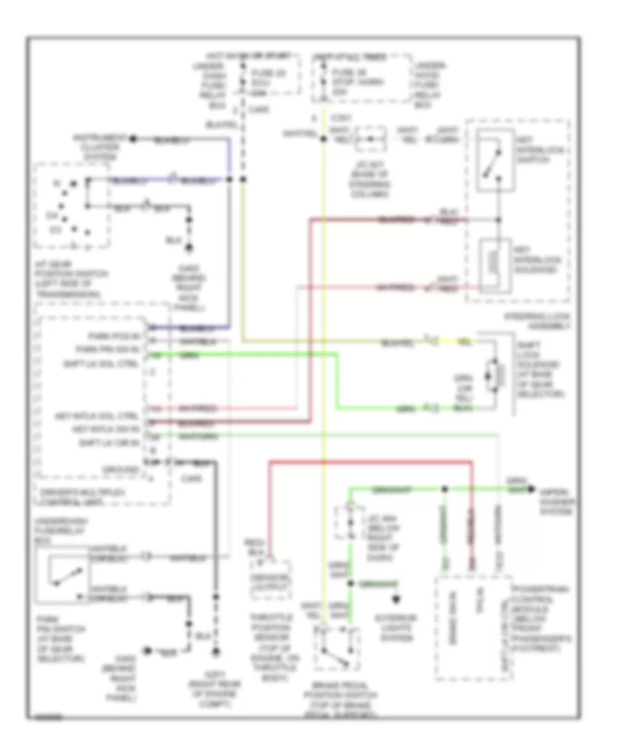
SHIFT INTERLOCK
Shift Interlock Wiring Diagram for Acura 3.5RL 2003
 https://portal-diagnostov.com/license.html
Automotive Electricians Portal FZCO
Automotive Electricians Portal FZCO
https://portal-diagnostov.com/license.html
https://portal-diagnostov.com/license.html
Automotive Electricians Portal FZCO
Automotive Electricians Portal FZCO
List of elements for Shift Interlock Wiring Diagram for Acura 3.5RL 2003:
- (top of engine, on throttle body)
- A/t gear position switch (left side of
- Brake pedal position switch (top of brake pedal support)
- Brake sw in
- C301
- C405
- C406
- Driver's multiplex control unit
- E22
- Exterior lights system
- Fuse 20 ecu 20a
- Fuse 39 stop, horn 20a
- G251 (right rear of engine compt)
- G402 (behind right kick panel)
- Ground
- Hot at all times
- Hot in on or start
- Instrument cluster system
- J/c 421 (base of steering column)
- J/c 464 (below right side of dash)
- Key interlock solenoid
- Key interlock switch
- Key intlk sol ctrl
- Key intlk sw in
- Park pin sw in
- Park pin switch (at base of gear selector)
- Park pos in
- Powertrain control module (below front passenger's footrest)
- Sensor output
- Shft lk cir ctrl
- Shft lk cir in
- Shft lk sol ctrl
- Shift lock solenoid (at base of gear selector)
- Steering lock assembly
- Throttle position sensor
- Tps in
- Transmission)
- Under- dash fuse/ relay box
- Under- hood fuse/ relay box
- Underdash fuse/relay box
- Wiper/ washer system
 Čeština
 Dansk
Dansk Deutsch
 Ελληνικά
 English
 English
 Español
 Suomi
Suomi Français
 Français
 עברית
עברית Hrvatski
 Magyar
 Italiano
 日本語
日本語 한국어
한국어 Nederlands
 Polski
 Português
 Português
 Română
 Русский
 Slovenčina
 Slovenščina
 Svenska
 Türkçe
 中文 (中国)
