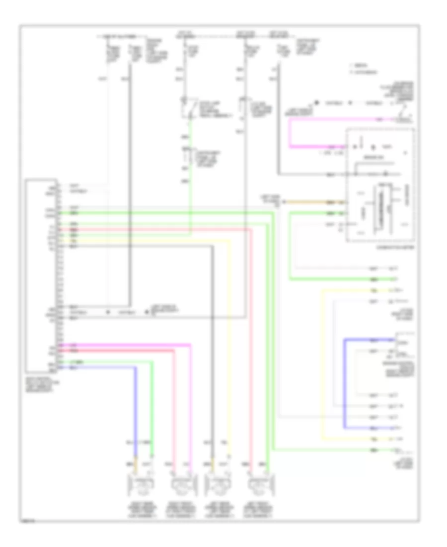
ANTI-LOCK BRAKES
Anti-lock Brakes Wiring Diagram for Toyota Yaris S 2007
 https://portal-diagnostov.com/license.html
Automotive Electricians Portal FZCO
Automotive Electricians Portal FZCO
https://portal-diagnostov.com/license.html
https://portal-diagnostov.com/license.html
Automotive Electricians Portal FZCO
Automotive Electricians Portal FZCO
List of elements for Anti-lock Brakes Wiring Diagram for Toyota Yaris S 2007:
- (left side of dash) d3
- (left side of engine compt) a2
- (on brake fluid reservoir) brake fluid level warning switch
- +bm
- +bs
- A1 (left side of engine compt)
- A21
- Abs ind
- Abs1/ vsc1 fuse 50a
- Abs2/ vsc2 fuse 30a
- B12
- B18
- B21
- B24
- Brake ind
- Can controller
- Can i/f
- Canh
- Canl
- Combination meter
- Cpu
- D76
- Ecu-ig fuse 10a
- Engine control module (right rear of engine compt)
- Engine room r/b (left side of engine compt)
- Fl+
- Fl-
- Fr+
- Fr-
- Gnd1
- Gnd2
- Hatchback
- Hot at all times
- Hot in on or start
- Ig1
- Instrument panel j/b (left side of dash)
- J/c a25 (left side of engine compt)
- J/c d41 (left side of dash)
- J/c d42 (right side of dash)
- Led driver
- Left front speed sensor (at left front hub assembly)
- Left rear speed sensor (left rear hub assembly)
- Met fuse 7.5a
- Pnk
- Red
- Right front speed sensor (at right front hub assembly)
- Right rear speed sensor (right rear hub assembly)
- Rl+
- Rl-
- Rr+
- Rr-
- Sedan
- Skid control ecu w/ actuator (left rear of engine compt)
- Stop fuse 10a
- Stop lamp switch (on brake pedal assembly)
- Stp
 Čeština
 Dansk
Dansk Deutsch
 Ελληνικά
 English
 English
 Español
 Suomi
Suomi Français
 Français
 עברית
עברית Hrvatski
 Magyar
 Italiano
 日本語
日本語 한국어
한국어 Nederlands
 Polski
 Português
 Português
 Română
 Русский
 Slovenčina
 Slovenščina
 Svenska
 Türkçe
 中文 (中国)
