ENGINE PERFORMANCE
4.0L
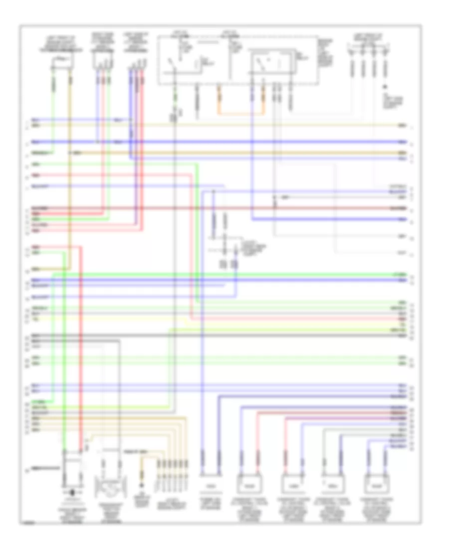
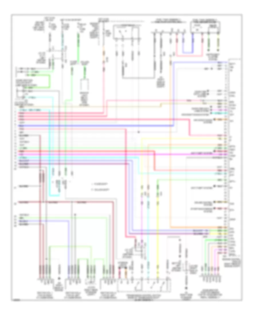
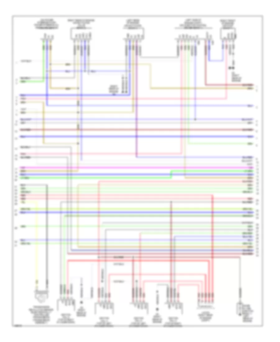
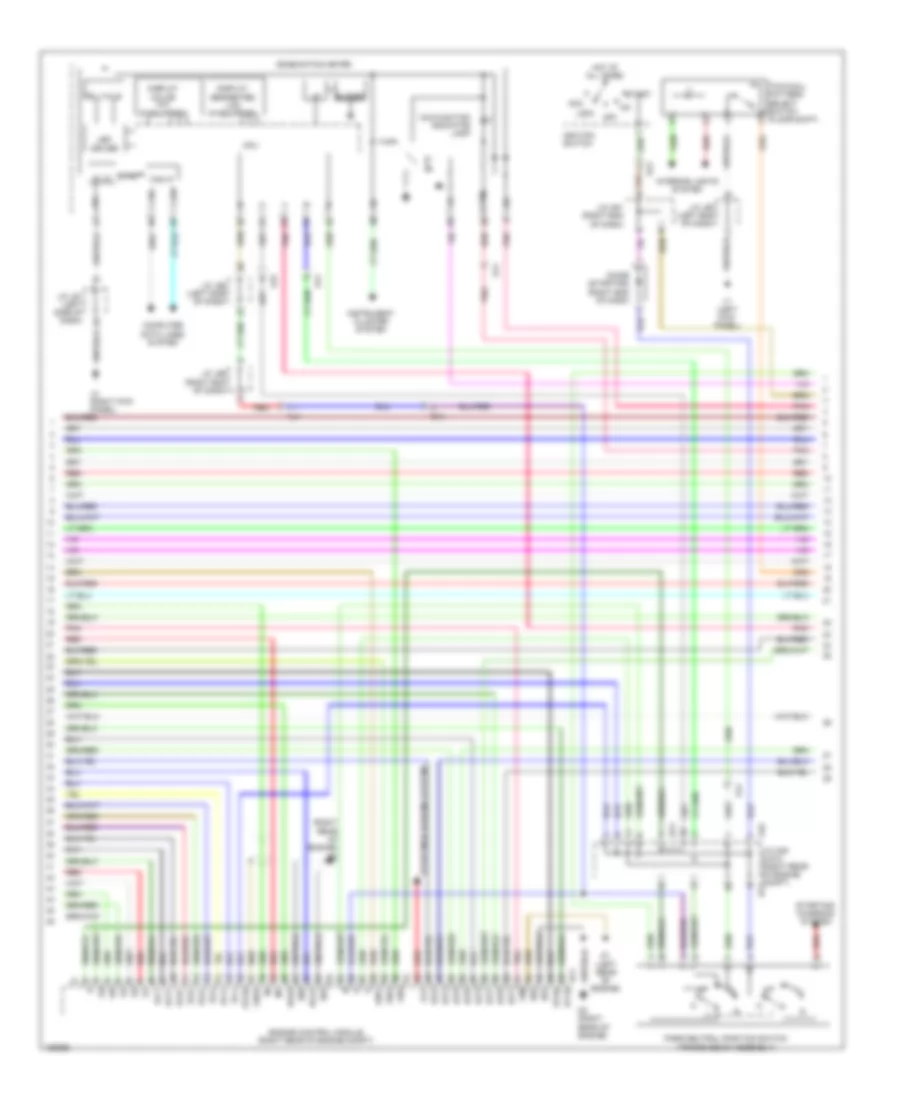
4.0L, Engine Performance Wiring Diagram (1 of 6) for Toyota Tundra Limited 2014
 https://portal-diagnostov.com/license.html
Automotive Electricians Portal FZCO
Automotive Electricians Portal FZCO
https://portal-diagnostov.com/license.html
https://portal-diagnostov.com/license.html
Automotive Electricians Portal FZCO
Automotive Electricians Portal FZCO
List of elements for 4.0L, Engine Performance Wiring Diagram (1 of 6) for Toyota Tundra Limited 2014:
- (air intake duct) mass air flow meter
- (left side of engine compt) vvt sensor (bank 1 exhaust side)
- (on throttle body) throttle position sensor
- (rear of engine compt) d9
- (right front of engine) power steering oil pressure switch
- (top left of engine) fuel injector 3
- (top left of engine) fuel injector 5
- (top of engine) fuel injector 1
- (top right of engine) fuel injector 2
- (top right of engine) fuel injector 4
- (top right of engine) fuel injector 6
- A1a+
- A1a-
- A2a+
- A2a-
- Air fuel ratio sensor (bank 1 sensor 1) (left side exhaust, before catalytic converter)
- Air fuel ratio sensor (bank 2 sensor 1) (right side exhaust, before catalytic converter)
- D74
- D8 (rear of engine compt)
- Da1
- Da2
- E2g
- Ekn2
- Eknk
- Engine control module (right rear of engine compt)
- Eta
- Ethw
- Ev1+
- Ev1-
- Ex+
- Ex-
- Ex1b
- Ex2b
- Ha1a
- Ha2a
- Heated oxygen sensor (bank 1 sensor 2) (left side exhaust, after catalytic converter)
- Heated oxygen sensor (bank 2 sensor 2) (right side exhaust, after catalytic converter)
- Ht1b
- Ht2b
- Igf1
- Knk1
- Knk2
- Knock sensor (bank 2) (left front of engine)
- Me01
- Nca
- Ne+
- Ne-
- Nsw
- Nt+
- Nt-
- Ox1b
- Ox2b
- Pnk
- Ppmp
- Psp
- Red
- Sp2+
- Sp2-
- Tha
- Tho1
- Tho2
- Thw
- Transmission revolution sensor (turbine) (in transmission)
- Vc2
- Vcta
- Vcv1
- Vcv2
- Vta
- Vta1
- Vta2
- Vv1+
- Vv1-
- Vv2+
- Vv2-
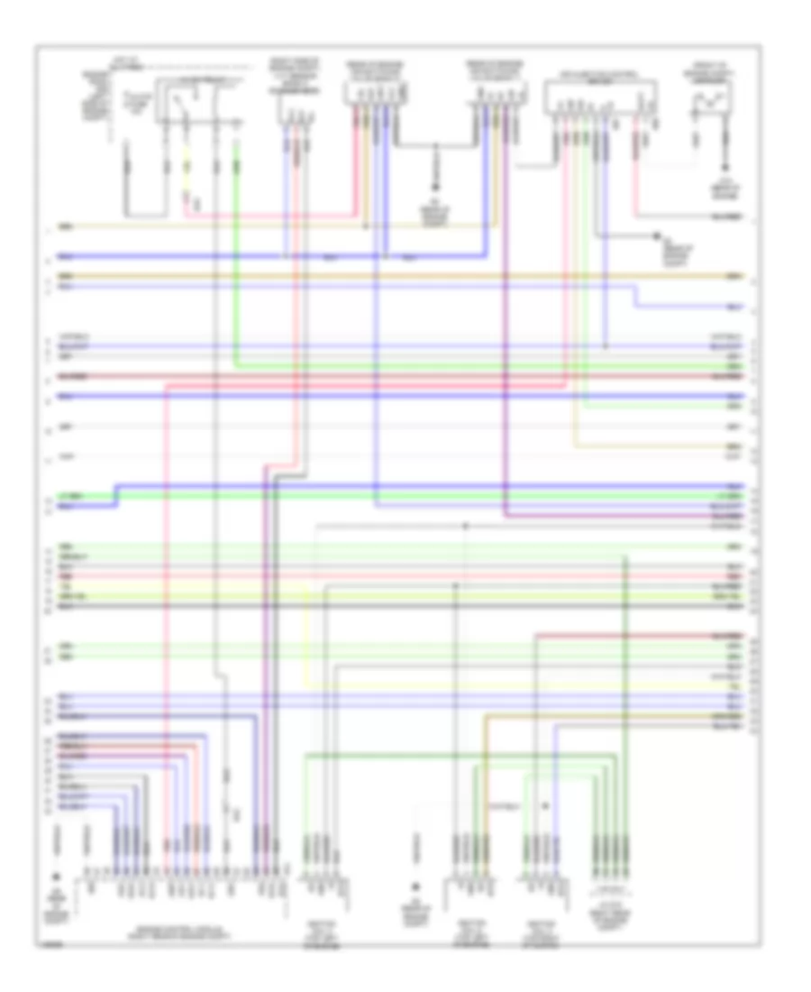
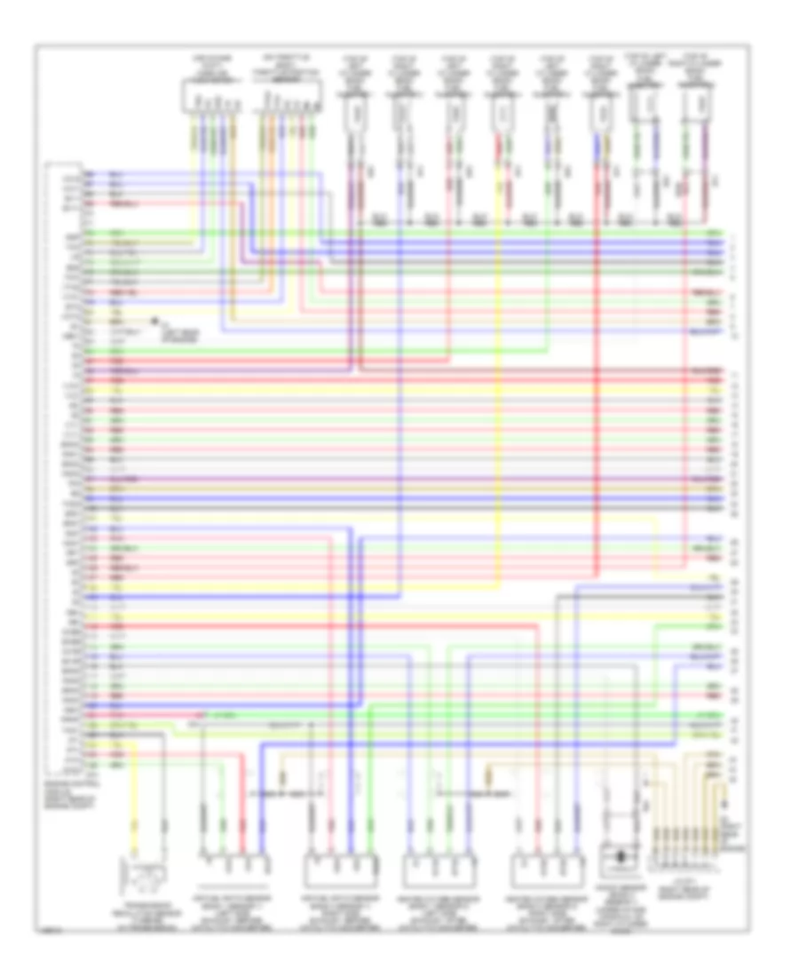
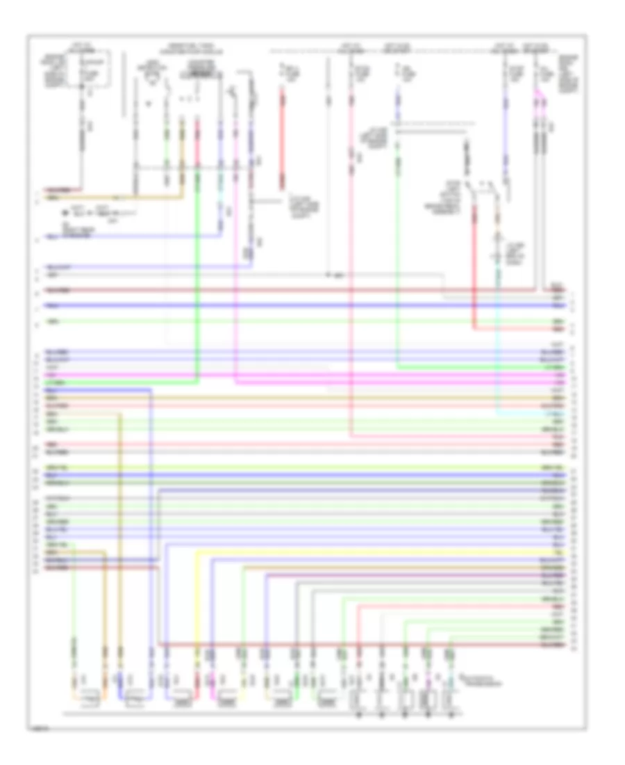
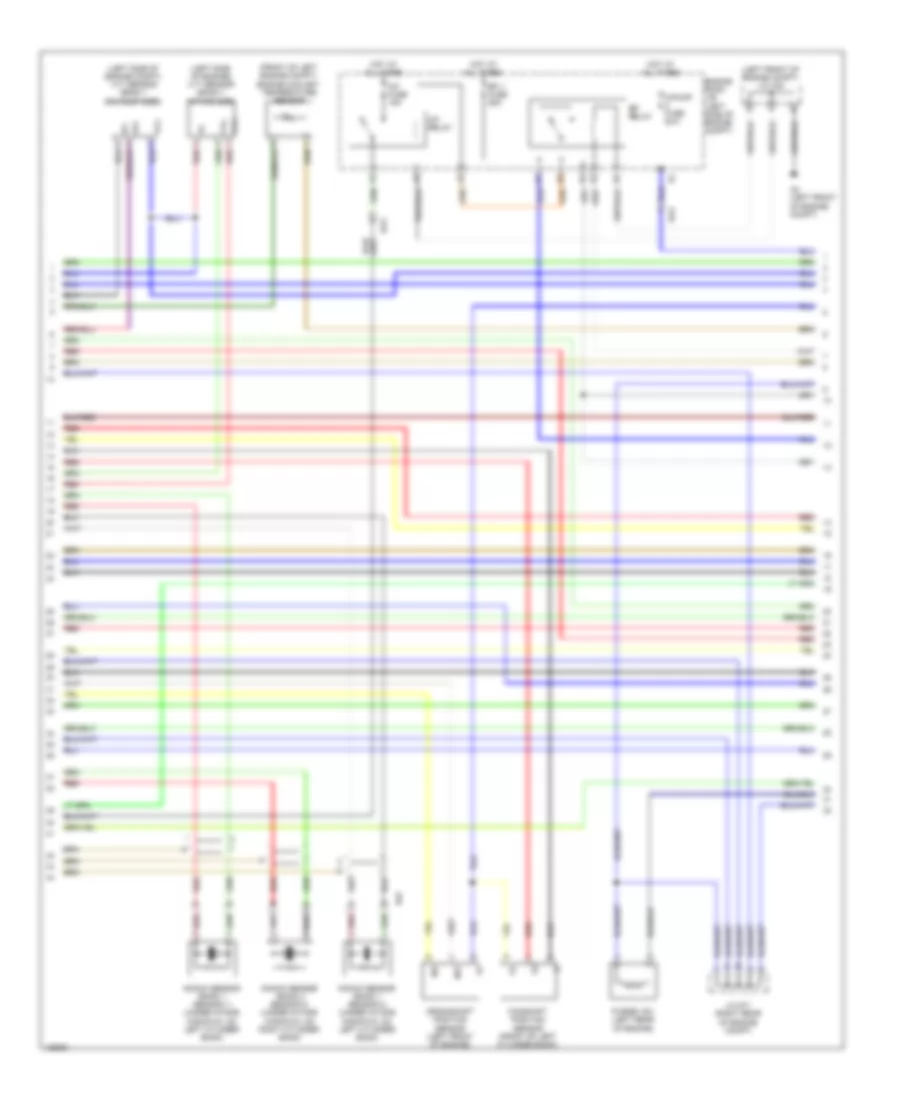
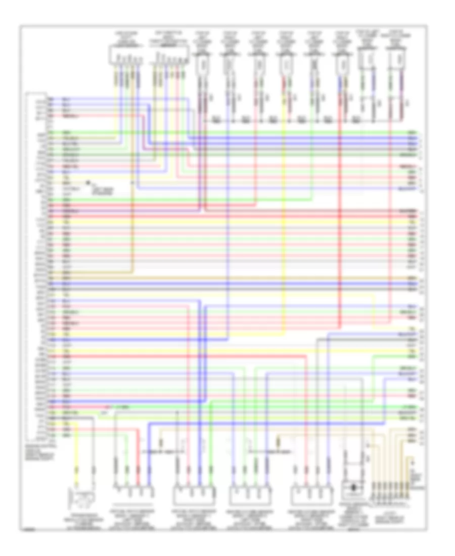
4.0L, Engine Performance Wiring Diagram (2 of 6) for Toyota Tundra Limited 2014
 https://portal-diagnostov.com/license.html
Automotive Electricians Portal FZCO
Automotive Electricians Portal FZCO
https://portal-diagnostov.com/license.html
https://portal-diagnostov.com/license.html
Automotive Electricians Portal FZCO
Automotive Electricians Portal FZCOList of elements for 4.0L, Engine Performance Wiring Diagram (2 of 6) for Toyota Tundra Limited 2014:
- (left front of engine compt) engine coolant temperature sensor
- (left front of engine compt) j/c a44
- (left side of engine) vvt sensor (bank 1 intake side)
- (right side of engine) vvt sensor (bank 2 intake side)
- A/f fuse 15a
- A/f relay
- A2 (left side of engine compt)
- Camshaft timing oil control valve (bank 1 exhaust side) (left front of engine)
- Camshaft timing oil control valve (bank 1) intake side) (left front of engine)
- Camshaft timing oil control valve (bank 2 exhaust side) (right front of engine)
- Camshaft timing oil control valve (bank 2) intake side) (right front of engine)
- Crankshaft position sensor (front of engine)
- D9 (rear of engine compt)
- Da3
- Da2
- Efi 1 fuse 25a
- Efi relay
- Engine room j/b (left side of engine compt)
- Hot at all times
- J/c d71 (right rear of engine compt)
- Knock sensor (bank 1) (right front of engine)
- Nca
- Purge vsv (left side of engine)
- Red
- Vvl+
- Vvl-
- Vvr+
- Vvr-
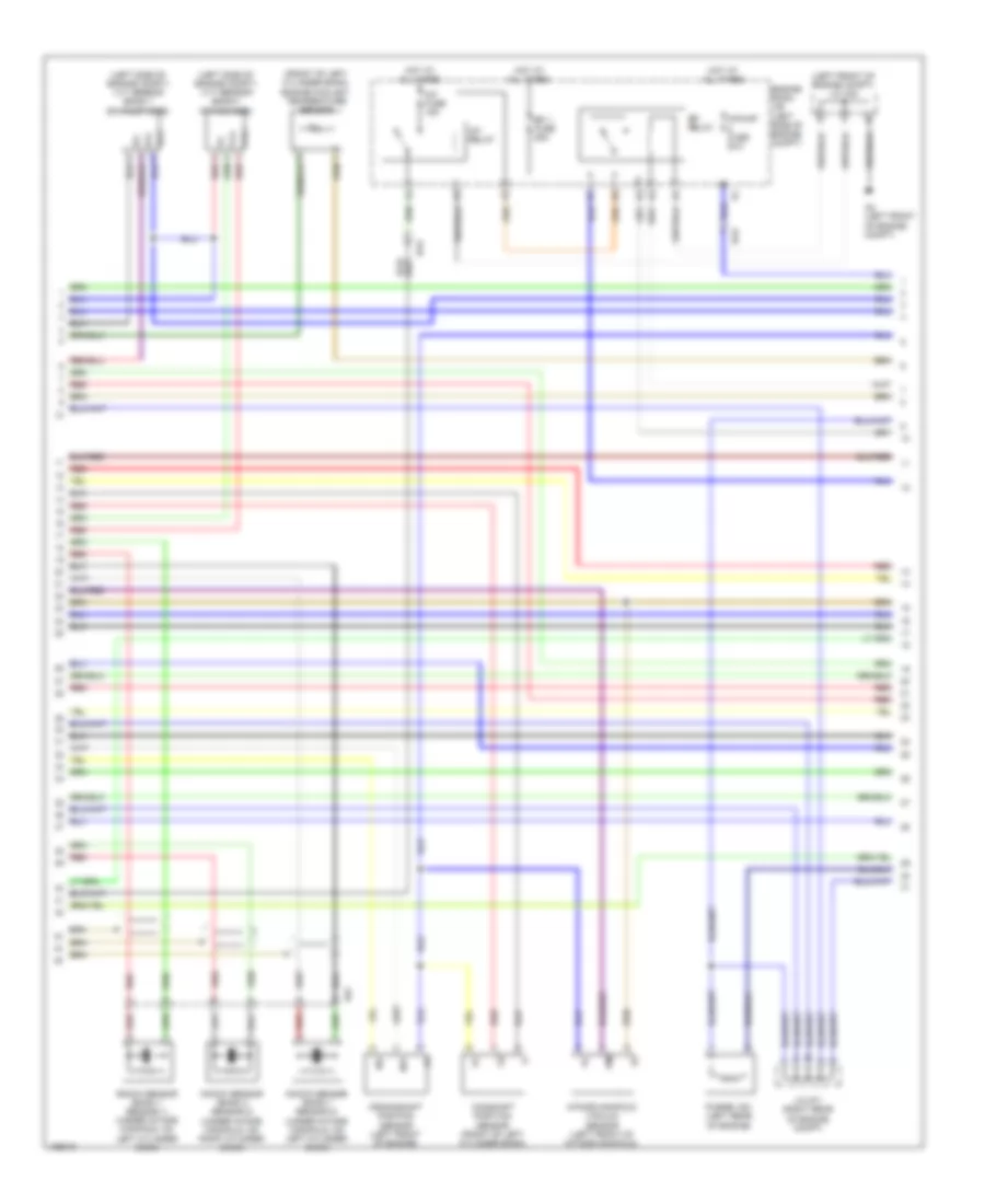
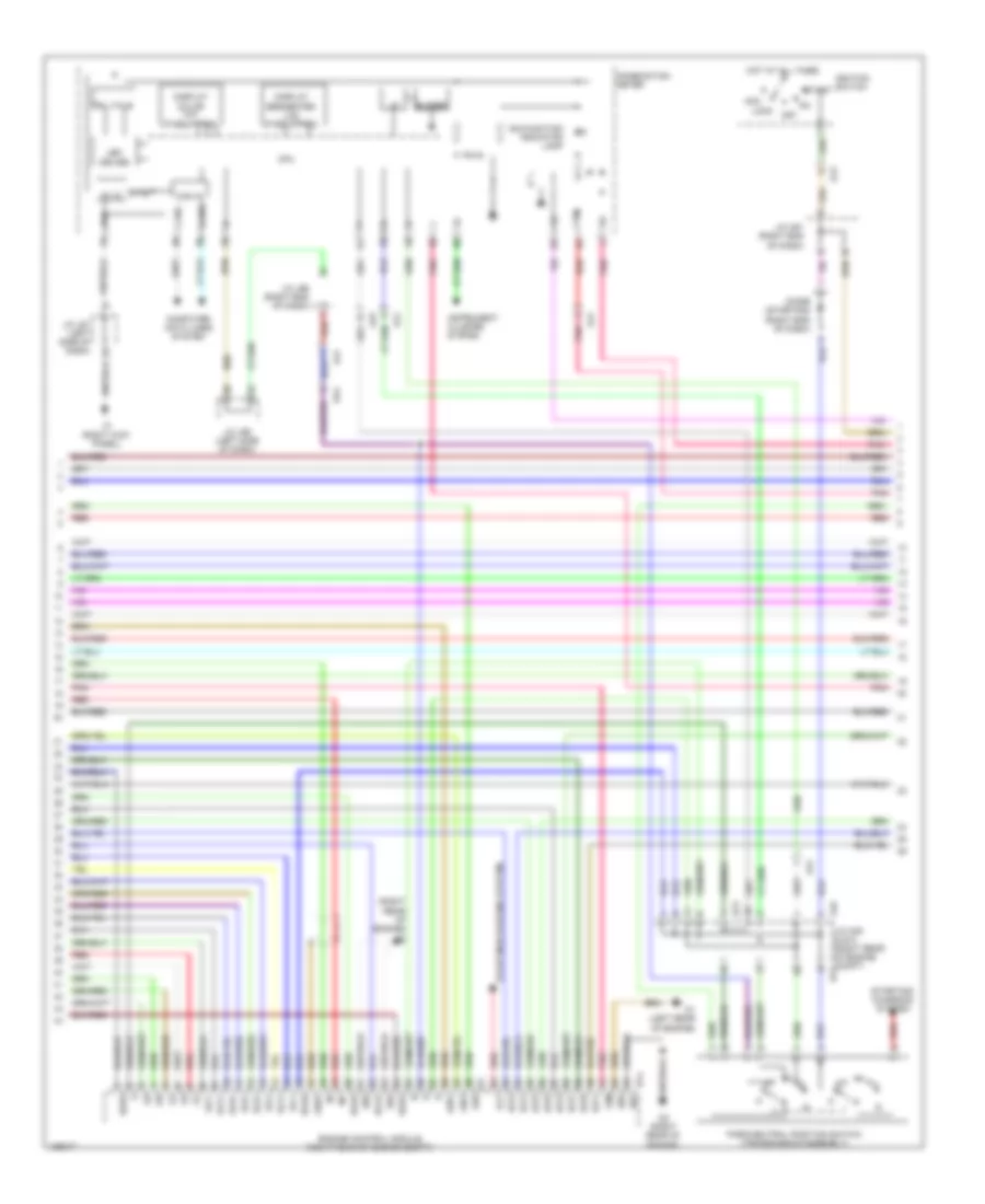
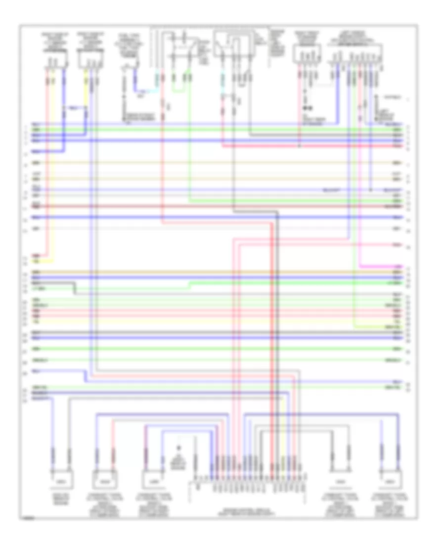
4.0L, Engine Performance Wiring Diagram (3 of 6) for Toyota Tundra Limited 2014
 https://portal-diagnostov.com/license.html
Automotive Electricians Portal FZCO
Automotive Electricians Portal FZCO
https://portal-diagnostov.com/license.html
https://portal-diagnostov.com/license.html
Automotive Electricians Portal FZCO
Automotive Electricians Portal FZCOList of elements for 4.0L, Engine Performance Wiring Diagram (3 of 6) for Toyota Tundra Limited 2014:
- (front of engine compt) air pump
- (rear of engine) air switching valve (bank 1)
- (rear of engine) air switching valve (bank 2)
- (right side of engine compt) vvt sensor (bank 2 exhaust side)
- +bl
- Ai-htr fuse 10a
- Ai-vsv relay
- Aip
- Aip2
- Air injection control driver
- Air1
- Airp
- Batt
- D10 (rear of engine)
- D74
- D8 (rear of engine compt)
- D86
- D87
- D9 (rear of engine compt)
- Da2
- E03
- E22
- Engine control module (right rear of engine compt)
- Engine room r/b (left side of engine compt)
- Ev2+
- Ev2-
- Ex+
- Ex-
- Gnd
- Gndl
- Hot at all times
- Igf
- Ignition coil 2 (top right of engine)
- Ignition coil 3 (top left of engine)
- Ignition coil 5 (top left of engine)
- Igt2
- Igt3
- Igt5
- J/c d72 (right rear of engine compt)
- Oc1+
- Oc1-
- Oc2+
- Oc2-
- Oe1+
- Oe1-
- Oe2+
- Oe2-
- Pnk
- Prg
- Red
- Sip
- Siv
- Vc2
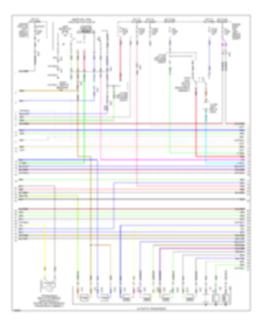
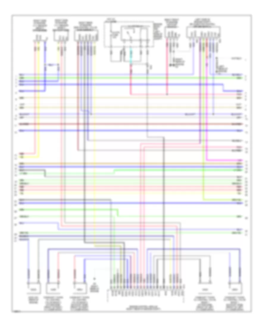
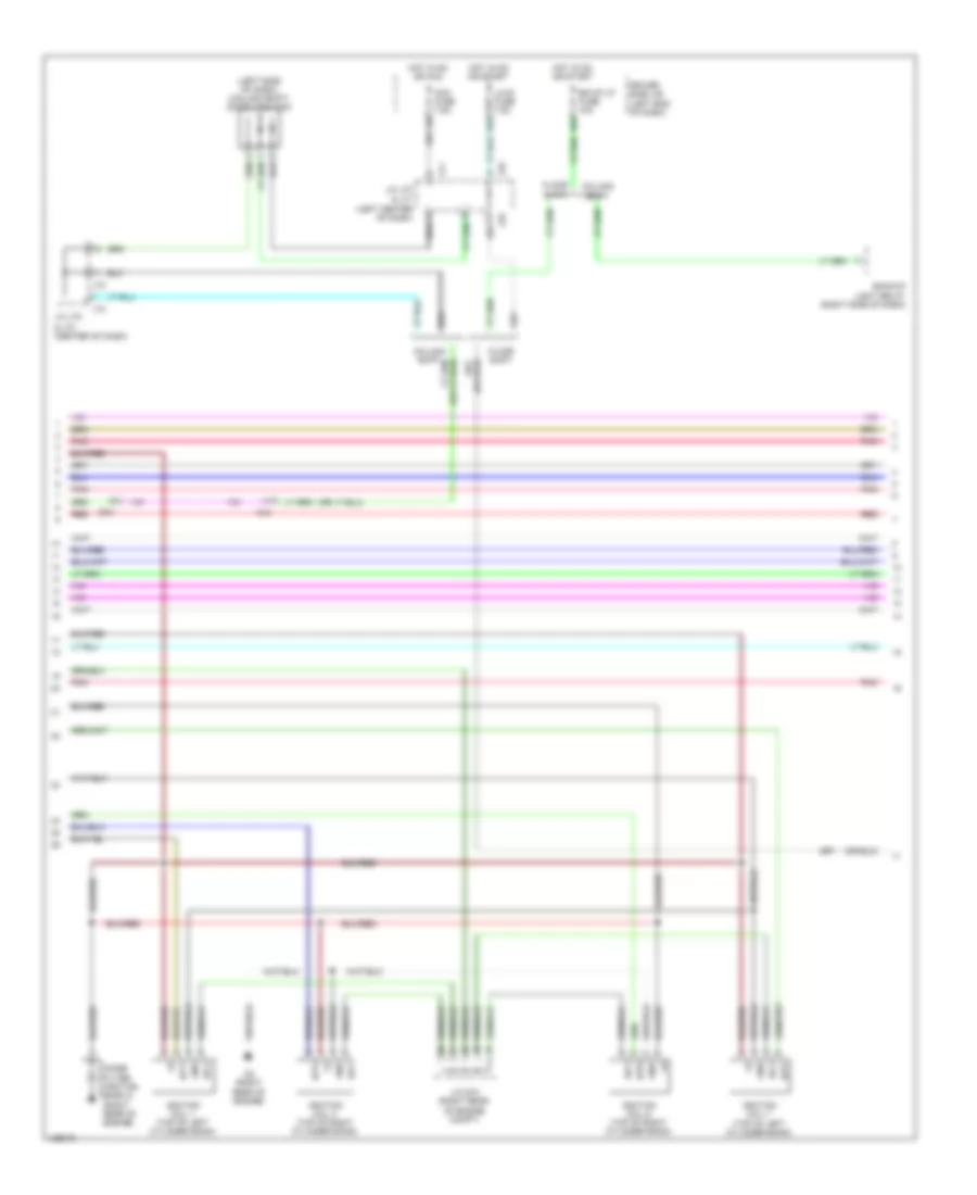
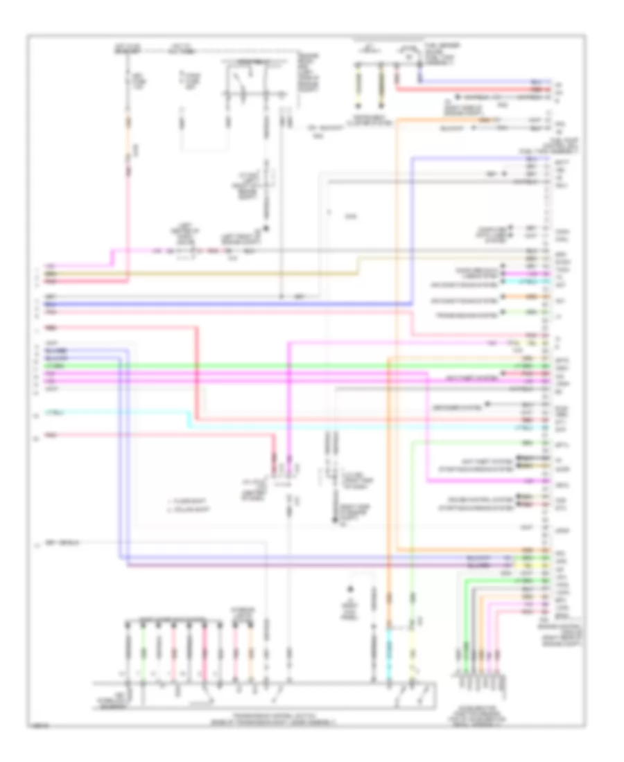
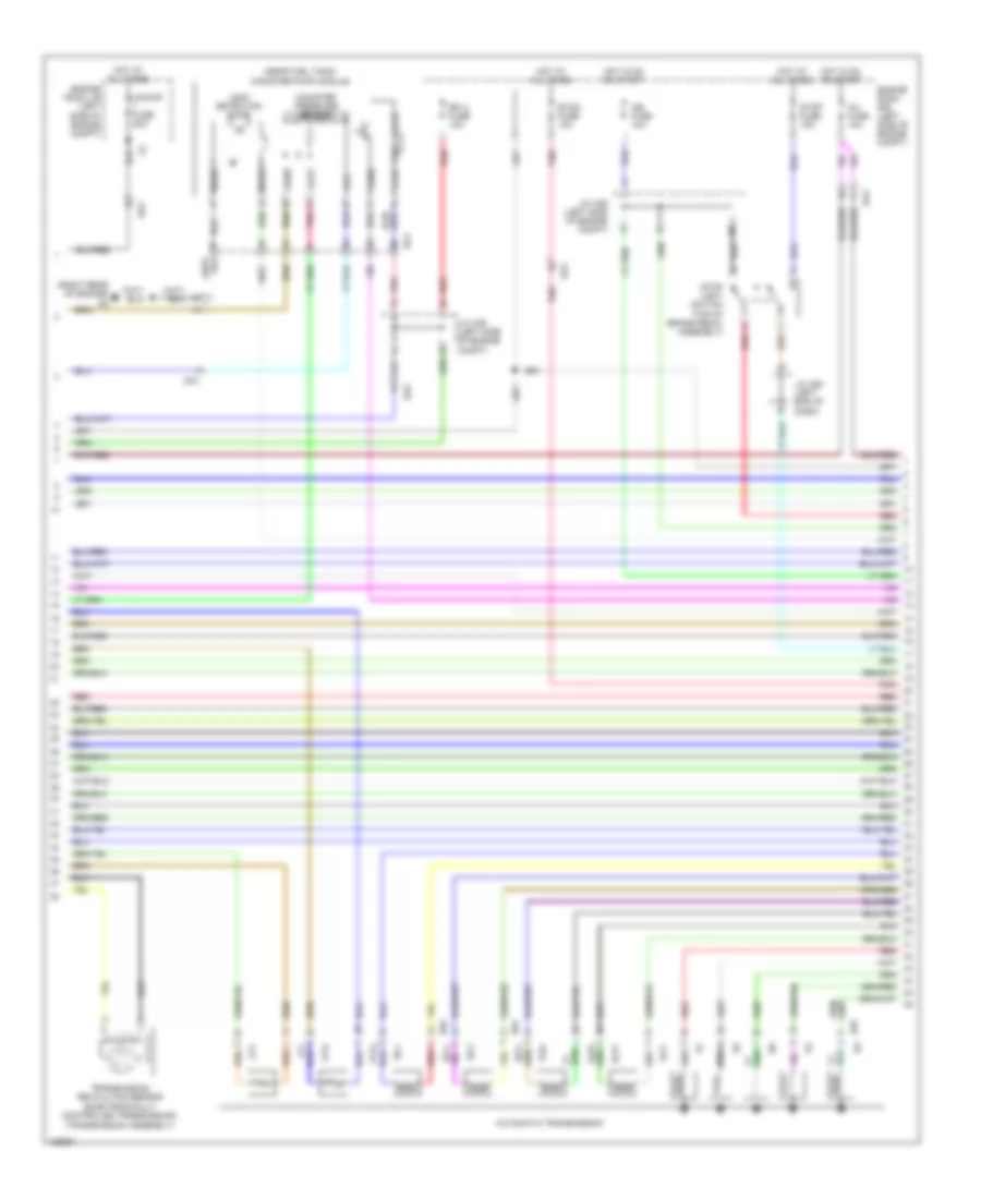
4.0L, Engine Performance Wiring Diagram (4 of 6) for Toyota Tundra Limited 2014
 https://portal-diagnostov.com/license.html
Automotive Electricians Portal FZCO
Automotive Electricians Portal FZCO
https://portal-diagnostov.com/license.html
https://portal-diagnostov.com/license.html
Automotive Electricians Portal FZCO
Automotive Electricians Portal FZCOList of elements for 4.0L, Engine Performance Wiring Diagram (4 of 6) for Toyota Tundra Limited 2014:
- (near fuel tank) canister pump module
- (right rear of engine) d9
- A/pump fuse 50a
- Automatic transmission
- Canister pressure sensor
- Da1
- Da2
- Da3
- Efi 2 fuse 10a
- Engine room j/b (left side of engine compt)
- Engine room r/b (left side of engine compt)
- Etcs fuse 10a
- F/pmp fuse 25a
- Hot at all times
- Hot in on or start
- Ign fuse 10a
- Inj fuse 10a
- J/c a49 (left side of engine compt)
- J/c a50 (left end of dash)
- Leak detection pump
- Ot+
- Ot-
- Ot2+
- Ot2-
- Pnk
- Ra1
- Red
- Sl1+
- Sl1-
- Sl2+
- Sl2-
- Slt+
- Slt-
- Slu+
- Slu-
- Stop fuse 15a
- Stop light switch (top of brake pedal assembly)
- Transmission revolution sensor (electronically controlled transmission) (transmission assembly)
- Vent valve
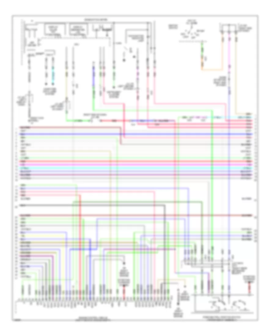
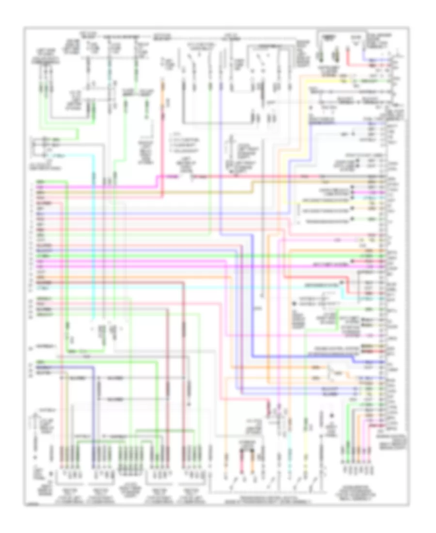
4.0L, Engine Performance Wiring Diagram (5 of 6) for Toyota Tundra Limited 2014
 https://portal-diagnostov.com/license.html
Automotive Electricians Portal FZCO
Automotive Electricians Portal FZCO
https://portal-diagnostov.com/license.html
https://portal-diagnostov.com/license.html
Automotive Electricians Portal FZCO
Automotive Electricians Portal FZCOList of elements for 4.0L, Engine Performance Wiring Diagram (5 of 6) for Toyota Tundra Limited 2014:
- (right end of dash) j/c j66
- (right kick panel) j3
- +bm
- 5v ic
- 5v+b
- A45
- Acc
- Aidi
- Airv
- Aj2
- Aj3
- Aj4
- Aj5
- Alt
- Buzzer
- Can if
- Canh
- Canl
- Chk
- Combination meter
- Computer data lines system
- Cpu
- D73
- D74
- D8 (right rear of engine)
- D9 (right rear of engine)
- Da4
- Diode (starting) (right end of dash)
- Display color tft (if equipped)
- Display segmented lcd (if equipped)
- E01
- E02
- E04
- E05
- Engine control module (right rear of engine compt)
- Ge01
- Ha1a
- Ha2a
- Hot at all times
- Ht1b
- Ht2b
- I/f
- Ig+
- Ignition switch
- Igt1
- Igt2
- Igt3
- Igt4
- Igt5
- Igt6
- Instrument cluster system
- J/c a45 & d73 (right rear of engine d73 compt)
- J/c a51 (right end of dash)
- J/c j61 (left side of dash)
- J/c j65 (left side of dash)
- J/c j70 (left center of dash)
- Led driver
- Lock
- Malfunction indicator lamp
- Off
- Park/neutral position switch (transmission assembly)
- Pnk
- Red
- Sl1+
- Sl1-
- Sl2+
- Sl2-
- Slt+
- Slt-
- Slu+
- Slu-
- Star
- Start
- Starting/ charging system
- Telltale
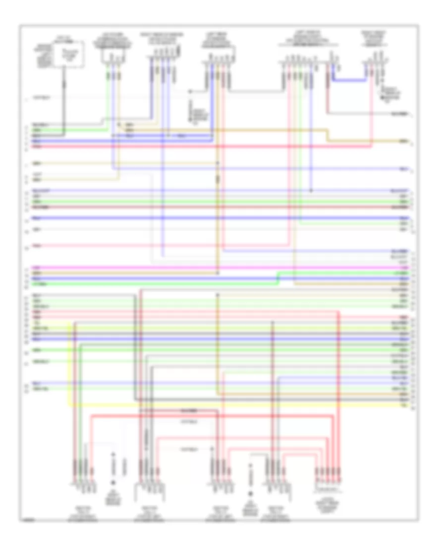
4.0L, Engine Performance Wiring Diagram (6 of 6) for Toyota Tundra Limited 2014
 https://portal-diagnostov.com/license.html
Automotive Electricians Portal FZCO
Automotive Electricians Portal FZCO
https://portal-diagnostov.com/license.html
https://portal-diagnostov.com/license.html
Automotive Electricians Portal FZCO
Automotive Electricians Portal FZCOList of elements for 4.0L, Engine Performance Wiring Diagram (6 of 6) for Toyota Tundra Limited 2014:
- (fuel tank assembly) fuel pump control ecu
- (fuel tank assembly) fuel sender gauge
- +b2
- A24
- A3 (right side of engine compt)
- A4 (right side of engine compt)
- Ac1
- Acc fuse 7.5a
- Accelerator position sensor (top of accelerator pedal assembly)
- Act
- Aip
- Aip2
- Air conditioning system
- Aj10
- Aj4
- Aj5
- Anti-theft system
- Backup light relay (right side of dash)
- Batt
- Bk/up lp fuse 10a
- Canh
- Canl
- Ccs
- Column shift
- Computer data lines system
- Cruise control system
- D55
- D65
- D9 (right rear of engine)
- Da4
- Diode (ignition) (column shift) (left side of dash)
- Driver side j/b (left end of dash)
- Engine control module (right rear of engine compt)
- Engine room r/b (left side of engine compt)
- Epa
- Epa2
- F/pmp relay
- Floor shift
- Fp-
- Fpc
- Gauge
- Gnd
- Hot in on or acc
- Hot in on or start
- Igf
- Ignition coil 1 (top of right cylinder bank)
- Ignition coil 6 (top of left cylinder bank)
- Ignition coil4 (top of left cylinder bank)
- Igsw
- Igt1
- Igt4
- Igt6
- Ill+
- Ill-
- Imi
- Imo
- Instrument cluster system
- Interior lights system
- J/c a52 (right end of dash)
- J/c d72 (right rear of engine compt)
- J/c j70 & j71 (left center of dash)
- J/c j72 & j73 (center of dash)
- J2 (bottom left center of dash)
- J70
- J71
- J72
- J73
- Lh-ig fuse 7.5a
- Met fuse 7.5a
- Mpmp
- Mrel
- Pnk
- Pump
- Ra1
- Ra2
- Red
- Sftd
- Sftu
- Spd
- St1-
- Sta
- Starting/charging system
- Stp
- Stsw
- Tach
- Transmission control switch (base of transmission shift lever assembly)
- Vcp2
- Vcpa
- Vpa
- Vpa2
- Vpmp
4.6L
4.6L, Engine Performance Wiring Diagram (1 of 8) for Toyota Tundra Limited 2014
 https://portal-diagnostov.com/license.html
Automotive Electricians Portal FZCO
Automotive Electricians Portal FZCO
https://portal-diagnostov.com/license.html
https://portal-diagnostov.com/license.html
Automotive Electricians Portal FZCO
Automotive Electricians Portal FZCOList of elements for 4.6L, Engine Performance Wiring Diagram (1 of 8) for Toyota Tundra Limited 2014:
- (air intake duct) mass air flow meter
- (on throttle body) throttle position sensor
- (top of left cylinder bank) fuel injector 1
- (top of left cylinder bank) fuel injector 3
- (top of left cylinder bank) fuel injector 5
- (top of left cylinder bank) fuel injector 7
- (top of right cylinder bank) fuel injector 2
- (top of right cylinder bank) fuel injector 4
- (top of right cylinder bank) fuel injector 6
- (top of right cylinder bank) fuel injector 8
- A1a+
- A1a-
- A2a+
- A2a-
- Air fuel ratio sensor (bank 1 sensor 1) (left side exhaust, before catalytic converter)
- Air fuel ratio sensor (bank 2 sensor 1) (right side exhaust, before catalytic converter)
- D1 (left rear of engine)
- D2 (right rear of engine)
- D74
- Da1
- Df1
- Dh1
- Da1
- E2g
- Ekn2
- Ekn3
- Ekn4
- Eknk
- Engine control module (right rear of engine compt)
- Eta
- Ev1+
- Ev1-
- Ex1b
- Ex2b
- G2-
- Ha1a
- Ha2a
- Heated oxygen sensor (bank 1 sensor 2) (left side exhaust, after catalytic converter)
- Heated oxygen sensor (bank 2 sensor 2) (right side exhaust, after catalytic converter)
- Ht1b
- Ht2b
- Igf1
- Igf2
- J/c d71 (right rear of engine compt)
- Knk1
- Knk2
- Knk3
- Knk4
- Knock sensor (bank 2 sensor 1) (under intake manifold, on right cylinder bank)
- Me01
- Nca
- Ne+
- Ne-
- Nsw
- Nt+
- Nt-
- Ox1b
- Ox2b
- Pim
- Pnk
- Ppmp
- Psp
- Red
- Sp2+
- Sp2-
- Tha
- Tho1
- Tho2
- Thw
- Transmission revolution sensor (turbine) (in transmission)
- Vcta
- Vcv1
- Vcv2
- Vta
- Vta1
- Vta2
- Vv1+
- Vv1-
- Vv2+
- Vv2-
4.6L, Engine Performance Wiring Diagram (2 of 8) for Toyota Tundra Limited 2014
 https://portal-diagnostov.com/license.html
Automotive Electricians Portal FZCO
Automotive Electricians Portal FZCO
https://portal-diagnostov.com/license.html
https://portal-diagnostov.com/license.html
Automotive Electricians Portal FZCO
Automotive Electricians Portal FZCOList of elements for 4.6L, Engine Performance Wiring Diagram (2 of 8) for Toyota Tundra Limited 2014:
- (front of left cylinder bank) engine coolant temperature sensor
- (left front of engine compt) j/c a44
- (left side of engine compt) vvt sensor (bank 1 exhaust side)
- (left side of engine compt) vvt sensor (bank 1 intake side)
- A/f fuse 15a
- A/f relay
- A/pump fuse 50a
- A2 (left front of engine compt)
- Camshaft position sensor (front of left cylinder bank)
- Crankshaft position sensor (left front of engine)
- Da3
- Da1
- Efi 1 fuse 25a
- Efi relay
- Engine room j/b (left side of engine compt)
- Ex+
- Ex-
- Hot at all times
- Intake manifold vacuum sensor (left front of intake manifold)
- J/c d71 (right rear of engine compt)
- Knock sensor (bank 1 sensor 1) (under intake manifold, on left cylinder bank)
- Knock sensor (bank 1 sensor 2) (under intake manifold, on left cylinder bank)
- Knock sensor (bank 2 sensor 2) (under intake manifold, on right cylinder bank)
- Ne+
- Ne-
- Pim
- Purge vsv (left rear of engine)
- Red
- Vc2
- Vvl+
- Vvl-
4.6L, Engine Performance Wiring Diagram (3 of 8) for Toyota Tundra Limited 2014
 https://portal-diagnostov.com/license.html
Automotive Electricians Portal FZCO
Automotive Electricians Portal FZCO
https://portal-diagnostov.com/license.html
https://portal-diagnostov.com/license.html
Automotive Electricians Portal FZCO
Automotive Electricians Portal FZCOList of elements for 4.6L, Engine Performance Wiring Diagram (3 of 8) for Toyota Tundra Limited 2014:
- (left rear of engine) d1
- (left side of engine compt) air injection control driver (bank 2)
- (right front of engine) air pump (bank 2)
- (right rear of engine) egr control valve sub-assembly
- (right side of engine) vvt sensor (bank 2 exhaust side)
- (right side of engine) vvt sensor (bank 2 intake side)
- +b1
- +b2
- Acis
- Acis vsv (rear of engine)
- Ai-htr fuse 10a
- Ai-htr relay
- Airp
- Aph+
- Aphg
- Arp2
- Bat2
- Camshaft timing oil control valve (bank 1 exhaust side) (front of left cylinder bank)
- Camshaft timing oil control valve (bank 1 intake side) (front of left cylinder bank)
- Camshaft timing oil control valve (bank 2 exhaust side) (front of right cylinder bank)
- Camshaft timing oil control valve (bank 2 intake side) (front of right cylinder bank)
- D2 (right rear of engine)
- D52
- D54
- D74
- Da2
- Da4
- Di2
- E03
- Egr1
- Egr2
- Egr3
- Egr4
- Engine control module (right rear of engine compt)
- Engine room r/b (left side of engine compt)
- Ev2+
- Ev2-
- Ex+
- Ex-
- Gnd
- Hai1
- Hot at all times
- Ht1b
- Ht2b
- Oc1+
- Oc1-
- Oc2+
- Oc2-
- Oe1+
- Oe1-
- Oe2+
- Oe2-
- Pnk
- Prg
- Red
- Sip2
- Siv2
- Vc2
- Vp2
- Vv2
- Vvr+
- Vvr-
4.6L, Engine Performance Wiring Diagram (4 of 8) for Toyota Tundra Limited 2014
 https://portal-diagnostov.com/license.html
Automotive Electricians Portal FZCO
Automotive Electricians Portal FZCO
https://portal-diagnostov.com/license.html
https://portal-diagnostov.com/license.html
Automotive Electricians Portal FZCO
Automotive Electricians Portal FZCOList of elements for 4.6L, Engine Performance Wiring Diagram (4 of 8) for Toyota Tundra Limited 2014:
- (left rear of engine) air switching (bank 1)
- (left side of engine compt) air injection control driver (bank 1)
- (on power steering pump) power steering oil pressure sensor
- (right front of engine) air pump (bank 1)
- (right rear of engine) air switching valve (bank 2)
- (right rear of engine) d3
- +bl
- Aip
- Aip2
- Aph+
- Aphg
- Batt
- D3 (right rear of engine)
- D48
- D50
- E22
- Gnd
- Gndl
- Igf2
- Ignition coil 2 (top of right cylinder bank)
- Ignition coil 3 (top of left cylinder bank)
- Ignition coil 5 (top of left cylinder bank)
- Ignition coil 8 (top of right cylinder bank)
- Igt2
- Igt3
- Igt5
- Igt8
- J/c d72 (right rear of engine compt)
- Noise filter (ignition bank 1) (left rear of engine)
- Pnk
- Psp
- Red
- Sip
- Siv
- Transmission revolution sensor (electronically controlled transmission) (transmission assembly)
- Vc2
4.6L, Engine Performance Wiring Diagram (5 of 8) for Toyota Tundra Limited 2014
 https://portal-diagnostov.com/license.html
Automotive Electricians Portal FZCO
Automotive Electricians Portal FZCO
https://portal-diagnostov.com/license.html
https://portal-diagnostov.com/license.html
Automotive Electricians Portal FZCO
Automotive Electricians Portal FZCOList of elements for 4.6L, Engine Performance Wiring Diagram (5 of 8) for Toyota Tundra Limited 2014:
- (near fuel tank) canister pump module
- A/pump fuse 50a
- Canister pressure sensor
- D2 (right rear of engine)
- Da1
- Da2
- Da3
- Efi 2 fuse 10a
- Engine room j/b (left side of engine compt)
- Engine room r/b (left side of engine compt)
- Etcs fuse 10a
- Hot at all times
- Hot in on or start
- Ign fuse 10a
- Inj fuse 10a
- J/c a49 (left side of engine compt)
- J/c a50 (left end of dash)
- Leak detection pump
- Ot+
- Ot-
- Ot2+
- Ot2-
- Pnk
- Ra1
- Red
- S3 automatic transmission
- Sl1+
- Sl1-
- Sl2+
- Sl2-
- Slt+
- Slt-
- Slu+
- Slu-
- Stop fuse 15a
- Stop light switch (top of brake pedal assembly)
- Vent valve
4.6L, Engine Performance Wiring Diagram (6 of 8) for Toyota Tundra Limited 2014
 https://portal-diagnostov.com/license.html
Automotive Electricians Portal FZCO
Automotive Electricians Portal FZCO
https://portal-diagnostov.com/license.html
https://portal-diagnostov.com/license.html
Automotive Electricians Portal FZCO
Automotive Electricians Portal FZCOList of elements for 4.6L, Engine Performance Wiring Diagram (6 of 8) for Toyota Tundra Limited 2014:
- (right rear of engine) d2
- +bm
- 5v ic
- 5v+b
- A45
- Acc
- Aid2
- Aidi
- Airv
- Aj3
- Aj4
- Aj5
- Alt
- Buzzer
- Can if
- Canh
- Canl
- Chk
- Combination meter
- Computer data lines system
- Cpu
- D1 (left rear of engine)
- D2 (right rear of engine)
- D73
- D74 e01
- Da4
- Diode (starting) (right end of dash)
- Display color tft (if equipped)
- Display segmented lcd (if equipped)
- E02
- E04
- E05
- Egr2
- Egr3
- Engine control module (right rear of engine compt)
- Ge01
- Ha1a
- Ha2a
- Hot at all times
- I/f
- Ig+
- Ignition switch
- Igt1
- Igt2
- Igt3
- Igt4
- Igt5
- Igt6
- Igt7
- Igt8
- Instrument cluster system
- J/c a45 & d73 (right rear of engine compt) d73
- J/c a51 (right end of dash)
- J/c j61 (left side of dash)
- J/c j65 (left side of dash)
- J/c j66 (right end of dash)
- J3 (right kick panel)
- Led driver
- Lock
- Malfunction indicator lamp
- Off
- Park/neutral position switch (transmission assembly)
- Pnk
- Red
- Sl1+
- Sl1-
- Sl2+
- Sl2-
- Slt+
- Slt-
- Slu+
- Slu-
- Star
- Start
- Starting/ charging system
- Starting/charging system
- Telltale
4.6L, Engine Performance Wiring Diagram (7 of 8) for Toyota Tundra Limited 2014
 https://portal-diagnostov.com/license.html
Automotive Electricians Portal FZCO
Automotive Electricians Portal FZCO
https://portal-diagnostov.com/license.html
https://portal-diagnostov.com/license.html
Automotive Electricians Portal FZCO
Automotive Electricians Portal FZCOList of elements for 4.6L, Engine Performance Wiring Diagram (7 of 8) for Toyota Tundra Limited 2014:
- & j71 (left center of dash)
- & j73 (center of dash)
- (left side of dash) (column shift) diode (ignition)
- Acc fuse 7.5a
- Aj2
- Backup light relay (right side of dash)
- Bk/up lp fuse 10a
- Column shift
- D3 (right rear of engine)
- D55
- D65
- Da4
- Driver side j/b (left end of dash)
- Floor shift
- Gnd
- Hot in on or acc
- Hot in on or start
- Igf1
- Ignition coil 1 (top of left cylinder bank)
- Ignition coil 4 (top of right cylinder bank)
- Ignition coil 6 (top of right cylinder bank)
- Ignition coil 7 (top of left cylinder bank)
- Igt1
- Igt4
- Igt6
- Igt7
- J/c d72 (right rear of engine compt)
- J/c j70
- J/c j72
- J70
- J71
- J72
- J73
- Lh-ig fuse 7.5a
- Noise filter (ignition bank 2) (right rear of engine)
- Pnk
- Red
4.6L, Engine Performance Wiring Diagram (8 of 8) for Toyota Tundra Limited 2014
 https://portal-diagnostov.com/license.html
Automotive Electricians Portal FZCO
Automotive Electricians Portal FZCO
https://portal-diagnostov.com/license.html
https://portal-diagnostov.com/license.html
Automotive Electricians Portal FZCO
Automotive Electricians Portal FZCOList of elements for 4.6L, Engine Performance Wiring Diagram (8 of 8) for Toyota Tundra Limited 2014:
- (left center of dash) j/c j70
- (right side of engine compt)
- +b2
- 2wd
- A2 (left front of engine compt)
- A24
- A4 (right side of engine compt)
- Ac1
- Accelerator position sensor (top of accelerator pedal assembly)
- Accr
- Act
- Adj1
- Aip
- Aip2
- Air conditioning system
- Aj10
- Aj4
- Aj5
- Anti-theft system
- Arv2
- Batt
- Canh
- Canl
- Ccs
- Column shift
- Computer data lines system
- Cruise control system
- Da4
- Defogger system
- Els2
- Engine control module (right rear of engine compt)
- Engine room r/b (left side of engine compt)
- Epa
- Epa2
- F/pmp fuse 25a
- F/pmp relay
- Floor shift
- Fp-
- Fpc
- Fuel pump control ecu (fuel tank assembly)
- Fuel sender gauge (fuel tank assembly)
- Hot at all times
- Hot in on or start
- Igsw
- Ill+
- Ill-
- Imi
- Imo
- Instrument cluster system
- Interior lights system
- J/c a44 (left front of engine compt)
- J/c a52 (right end of dash)
- J/c j72 & j73 (center of dash)
- J3 (right kick panel)
- J72
- J73
- Key interlock solenoid
- Met fuse 7.5a
- Mpmp
- Mrel
- Pnk
- Pump
- Ra1
- Ra2
- Red
- Sftd
- Sftu
- Shift interlock system
- Sls+
- Spd
- St1-
- Sta
- Starting/charging system
- Stp
- Stsw
- Tach
- Transmission control switch (base of transmission shift lever assembly)
- Transmissions system
- Vcp2
- Vcpa
- Vpa
- Vpa2
- Vpmp
5.7L
5.7L, Engine Performance Wiring Diagram (1 of 7) for Toyota Tundra Limited 2014
 https://portal-diagnostov.com/license.html
Automotive Electricians Portal FZCO
Automotive Electricians Portal FZCO
https://portal-diagnostov.com/license.html
https://portal-diagnostov.com/license.html
Automotive Electricians Portal FZCO
Automotive Electricians Portal FZCOList of elements for 5.7L, Engine Performance Wiring Diagram (1 of 7) for Toyota Tundra Limited 2014:
- (air intake duct) mass air flow meter
- (on throttle body) throttle position sensor
- (top of left cylinder bank) fuel injector 1
- (top of left cylinder bank) fuel injector 3
- (top of left cylinder bank) fuel injector 5
- (top of left cylinder bank) fuel injector 7
- (top of right cylinder bank) fuel injector 2
- (top of right cylinder bank) fuel injector 4
- (top of right cylinder bank) fuel injector 6
- (top of right cylinder bank) fuel injector 8
- A1a+
- A1a-
- A2a+
- A2a-
- Air fuel ratio sensor (bank 1 sensor 1) (left side exhaust, before catalytic converter)
- Air fuel ratio sensor (bank 2 sensor 1) (right side exhaust, before catalytic converter)
- D1 (left rear of engine)
- D2 (right rear of engine)
- D74
- Da1
- Df1
- Dh1
- Da1
- E2g
- Ekn2
- Ekn3
- Ekn4
- Eknk
- Engine control module (right rear of engine compt)
- Eta
- Etha
- Ethw
- Ev1+
- Ev1-
- Ex1b
- Ex2b
- G2-
- Ha1a
- Ha2a
- Heated oxygen sensor (bank 1 sensor 2) (left side exhaust, after catalytic converter)
- Heated oxygen sensor (bank 2 sensor 2) (right side exhaust, after catalytic converter)
- Ht1b
- Ht2b
- Igf1
- Igf2
- J/c d71 (right rear of engine compt)
- Knk1
- Knk2
- Knk3
- Knk4
- Knock sensor (bank 2 sensor 1) (under intake manifold, on right cylinder bank)
- Me01
- Nca
- Ne+
- Ne-
- Nsw
- Nt+
- Nt-
- Ox1b
- Ox2b
- Pnk
- Ppmp
- Psp
- Red
- Sp2+
- Sp2-
- Tha
- Tho1
- Tho2
- Thw
- Transmission revolution sensor (turbine) (in transmission)
- Vcta
- Vcv1
- Vcv2
- Vta
- Vta1
- Vta2
- Vv1+
- Vv1-
- Vv2+
- Vv2-
5.7L, Engine Performance Wiring Diagram (2 of 7) for Toyota Tundra Limited 2014
 https://portal-diagnostov.com/license.html
Automotive Electricians Portal FZCO
Automotive Electricians Portal FZCO
https://portal-diagnostov.com/license.html
https://portal-diagnostov.com/license.html
Automotive Electricians Portal FZCO
Automotive Electricians Portal FZCOList of elements for 5.7L, Engine Performance Wiring Diagram (2 of 7) for Toyota Tundra Limited 2014:
- (front of left engine compt) engine coolant temperature sensor
- (left front of engine compt) j/c a44
- (left side of engine compt) vvt sensor (bank 1 exhaust side)
- (left side of engine) vvt sensor (bank 1 intake side)
- A/f fuse 15a
- A/f relay
- A/pump fuse 50a
- A2 (left front of engine compt)
- Camshaft position sensor (front of left cylinder bank)
- Crankshaft position sensor (left front of engine)
- Da3
- Da1
- Efi 1 fuse 25a
- Efi relay
- Engine room j/b (left side of engine compt)
- Ex+
- Ex-
- Hot at all times
- J/c d71 (right rear of engine compt)
- Knock sensor (bank 1 sensor 1) (under intake manifold, on left cylinder bank)
- Knock sensor (bank 1 sensor 2) (under intake manifold, on left cylinder bank)
- Knock sensor (bank 2 sensor 2) (under intake manifold, on right cylinder bank)
- Ne+
- Ne-
- Purge vsv (left rear of engine)
- Red
- Vc2
- Vvl+
- Vvl-
5.7L, Engine Performance Wiring Diagram (3 of 7) for Toyota Tundra Limited 2014
 https://portal-diagnostov.com/license.html
Automotive Electricians Portal FZCO
Automotive Electricians Portal FZCO
https://portal-diagnostov.com/license.html
https://portal-diagnostov.com/license.html
Automotive Electricians Portal FZCO
Automotive Electricians Portal FZCOList of elements for 5.7L, Engine Performance Wiring Diagram (3 of 7) for Toyota Tundra Limited 2014:
- (fuel tank assembly) (5.7l flex fuel) fuel tank solenoid valve
- (left rear of engine) d1
- (left side of engine compt) air injection control driver (bank 2)
- (rear of right frame member) r1
- (right front of engine) air pump (bank 2)
- (right side of engine) vvt sensor (bank 2 exhaust side)
- (right side of engine) vvt sensor (bank 2 intake side)
- +b2
- Acis
- Acis vsv (rear of engine)
- Ai htr relay
- Airp
- Aph+
- Aphg
- Arp2
- Bat2
- Camshaft timing oil control valve (bank 1 exhaust side) (front of left cylinder bank)
- Camshaft timing oil control valve (bank 1 intake side) (front of left cylinder bank)
- Camshaft timing oil control valve (bank 2 exhaust side) (front of right cylinder bank)
- Camshaft timing oil control valve (bank 2 intake side) (front of right cylinder bank)
- D2 (right rear of engine)
- D3 (right rear of engine)
- D52
- D54
- D74
- Da1
- Da2
- Da4
- Di2
- E03
- Engine control module (right rear of engine compt)
- Engine room r/b (left side of engine compt)
- Ev2+
- Ev2-
- Ex+
- Ex-
- F/pmp vsv relay (5.7l flex fuel)
- Fpcr
- Gnd
- Hai1
- Oc1+
- Oc1-
- Oc2+
- Oc2-
- Oe1+
- Oe1-
- Oe2+
- Oe2-
- Pnk
- Prg
- Ra1
- Red
- Sip2
- Siv2
- Vc2
- Vp2
- Vv2
- Vvr+
- Vvr-
5.7L, Engine Performance Wiring Diagram (4 of 7) for Toyota Tundra Limited 2014
 https://portal-diagnostov.com/license.html
Automotive Electricians Portal FZCO
Automotive Electricians Portal FZCO
https://portal-diagnostov.com/license.html
https://portal-diagnostov.com/license.html
Automotive Electricians Portal FZCO
Automotive Electricians Portal FZCOList of elements for 5.7L, Engine Performance Wiring Diagram (4 of 7) for Toyota Tundra Limited 2014:
- (left rear of engine) air switching valve (bank 1)
- (left side of engine compt) air injection control driver (bank 1)
- (on power steering pump) power steering oil pressure sensor
- (right front of engine) air pump (bank 1)
- (right rear of engine) air switching valve (bank 2)
- (right rear of engine) d3
- +b d50
- +bl
- Ai-htr fuse 10a
- Aip
- Aip2
- Aph+ pnk
- Batt
- D3 (right rear of engine)
- E22
- Engine room r/b (left side of engine compt)
- Gnd
- Gndl
- Hot at all times
- Igf2
- Ignition coil 2 (top of right cylinder bank)
- Ignition coil 3 (top of left cylinder bank)
- Ignition coil 5 (top of left cylinder bank)
- Ignition coil 8 (top of right cylinder bank)
- Igt2
- Igt3
- Igt5
- Igt8
- J/c d72 (right rear of engine compt)
- Pnk
- Psp
- Red
- Sip
- Siv
- Vc2
- Vp d48
5.7L, Engine Performance Wiring Diagram (5 of 7) for Toyota Tundra Limited 2014
 https://portal-diagnostov.com/license.html
Automotive Electricians Portal FZCO
Automotive Electricians Portal FZCO
https://portal-diagnostov.com/license.html
https://portal-diagnostov.com/license.html
Automotive Electricians Portal FZCO
Automotive Electricians Portal FZCOList of elements for 5.7L, Engine Performance Wiring Diagram (5 of 7) for Toyota Tundra Limited 2014:
- (near fuel tank) canister pump module
- (right rear of engine) d2
- A/pump fuse 50a
- Automatic transmission
- Canister pressure sensor
- D63
- D64
- Da1
- Da2
- Da3
- Efi 2 fuse 10a
- Engine room j/b (left side of engine compt)
- Engine room r/b (left side of engine compt)
- Etcs fuse 10a
- Hot at all times
- Hot in on or start
- Ign fuse 10a
- Inj fuse 10a
- J/c a49 (left side of engine compt)
- J/c a50 (left end of dash)
- Leak detection pump
- Mgnd
- Mtrb
- Ot+
- Ot-
- Ot2+
- Ot2-
- Pnk
- Ra1
- Red
- Sgnd
- Sl1+
- Sl1-
- Sl2+
- Sl2-
- Slt+
- Slt-
- Slu+
- Slu-
- Stop fuse 15a
- Stop light switch (top of brake pedal assembly)
- Transmission revolution sensor (electronically controlled transmission) (transmission assembly)
- Vcc
- Vent valve
- Vgnd
- Vlvb
- Vout
5.7L, Engine Performance Wiring Diagram (6 of 7) for Toyota Tundra Limited 2014
 https://portal-diagnostov.com/license.html
Automotive Electricians Portal FZCO
Automotive Electricians Portal FZCO
https://portal-diagnostov.com/license.html
https://portal-diagnostov.com/license.html
Automotive Electricians Portal FZCO
Automotive Electricians Portal FZCOList of elements for 5.7L, Engine Performance Wiring Diagram (6 of 7) for Toyota Tundra Limited 2014:
- (right rear of engine) d2
- +bm
- 5v ic
- 5v+b
- A45
- Acc
- Aid2
- Aidi
- Airv
- Aj3
- Aj4
- Aj5
- Alt
- Buzzer
- Can if
- Canh
- Canl
- Chk
- Combination meter
- Computer data lines system
- Cpu
- D1 (left rear of engine)
- D2 (right rear of engine)
- D73
- D74
- Da4
- Diode (starting) (right end of dash)
- Display color tft (if equipped)
- Display segmented lcd (if equipped)
- E01
- E02
- E04
- E05
- Engine control module (right rear of engine compt)
- Ge01
- Ha1a
- Ha2a
- Hot at all times
- Ht1b
- Ht2b
- I/f
- Ig+
- Ignition switch
- Igt1
- Igt2
- Igt3
- Igt4
- Igt5
- Igt6
- Igt7
- Igt8
- Instrument cluster system
- Interior lights system
- J/c a45 & d73 (right rear of engine compt) d73
- J/c a51 (right end of dash)
- J/c j60 (left end of dash)
- J/c j61 (left side of dash)
- J/c j65 (left side of dash)
- J/c j66 (right end of dash)
- J1 (left kick panel)
- J3 (right kick panel)
- Led driver
- Lock
- Malfunction indicator lamp
- Off
- Park/neutral position switch (transmission assembly)
- Pnk
- Red
- Sl1+
- Sl1-
- Sl2+
- Sl2-
- Slt+
- Slt-
- Slu+
- Slu-
- Star
- Start
- Starting/ charging system
- Starting/charging system
- Telltale
- Tow/haul pattern select switch (floor shift)
5.7L, Engine Performance Wiring Diagram (7 of 7) for Toyota Tundra Limited 2014
 https://portal-diagnostov.com/license.html
Automotive Electricians Portal FZCO
Automotive Electricians Portal FZCO
https://portal-diagnostov.com/license.html
https://portal-diagnostov.com/license.html
Automotive Electricians Portal FZCO
Automotive Electricians Portal FZCOList of elements for 5.7L, Engine Performance Wiring Diagram (7 of 7) for Toyota Tundra Limited 2014:
- (5.7l flex fuel) c/opn relay
- (left center of dash) j/c j70
- (left front of engine compt) a2
- (left side of dash) (column shift) diode (ignition)
- (pin 6 to 9 not used)
- +b2
- 2wd
- 5.7l
- 5.7l flex fuel
- A24
- A3 (right side of engine compt)
- A4 (right side of engine compt)
- Ac1
- Acc fuse 7.5a
- Accelerator position sensor (top of accelerator pedal assembly)
- Accr
- Act
- Adj1
- Aip
- Aip2
- Air conditioning system
- Aj10
- Aj2
- Aj4
- Aj5
- Anti-theft system
- Arv2
- Backup light relay (right side of dash)
- Batt
- Bk/up lp fuse 10a
- Canh
- Canl
- Ccs
- Column shift
- Computer data lines system
- Cruise control system
- D3 (right rear of engine)
- D55
- D65
- Da4
- Defogger system
- Driver side j/b (left end of dash)
- Els2
- Engine control module (right rear of engine compt)
- Engine room r/b (left side of engine compt)
- Epa
- Epa2
- F/pmp fuse 25a
- F/pmp relay
- Floor shift
- Fp-
- Fpc
- Fuel pump control ecu (fuel tank assembly)
- Fuel sender gauge (fuel tank assembly)
- Gnd
- Hot at all times
- Hot in on or acc
- Hot in on or start
- Igf1
- Ignition coil 1 (top of left cylinder bank)
- Ignition coil 4 (top of right cylinder bank)
- Ignition coil 6 (top of right cylinder bank)
- Ignition coil 7 (top of left cylinder bank)
- Igsw
- Igt1
- Igt4
- Igt6
- Igt7
- Ill+
- Ill-
- Imi
- Imo
- Instrument cluster system
- Interior lights system
- J/c a44 (left front of engine compt)
- J/c a52 (right end of dash)
- J/c d72 (right rear of engine compt)
- J/c j60 (left end of dash)
- J/c j70 & j71 (left center of dash)
- J/c j72 & j73 (center of dash)
- J1 (left kick panel)
- J2 (right kick panel)
- J70
- J71
- J72
- J73
- Lh-ig fuse 7.5a
- Met fuse 7.5a
- Mpmp
- Mrel
- Pnk
- Pump
- Pwr
- R11
- Ra1
- Ra2
- Ra4
- Red
- Sender
- Sftd
- Sftu
- Spd
- St1-
- Sta
- Starting/ charging system
- Starting/charging system
- Stp
- Stsw
- Tach
- Transmission control switch (base of transmission shift lever assembly)
- Transmissions system
- Vcp2
- Vcpa
- Vpa
- Vpa2
- Vpmp
5.7L FLEX FUEL
5.7L Flex Fuel, Engine Performance Wiring Diagram (1 of 7) for Toyota Tundra Limited 2014
 https://portal-diagnostov.com/license.html
Automotive Electricians Portal FZCO
Automotive Electricians Portal FZCO
https://portal-diagnostov.com/license.html
https://portal-diagnostov.com/license.html
Automotive Electricians Portal FZCO
Automotive Electricians Portal FZCOList of elements for 5.7L Flex Fuel, Engine Performance Wiring Diagram (1 of 7) for Toyota Tundra Limited 2014:
- (air intake duct) mass air flow meter
- (on throttle body) throttle position sensor
- (top of left cylinder bank) fuel injector 1
- (top of left cylinder bank) fuel injector 3
- (top of left cylinder bank) fuel injector 5
- (top of left cylinder bank) fuel injector 7
- (top of right cylinder bank) fuel injector 2
- (top of right cylinder bank) fuel injector 4
- (top of right cylinder bank) fuel injector 6
- (top of right cylinder bank) fuel injector 8
- A1a+
- A1a-
- A2a+
- A2a-
- Air fuel ratio sensor (bank 1 sensor 1) (left side exhaust, before catalytic converter)
- Air fuel ratio sensor (bank 2 sensor 1) (right side exhaust, before catalytic converter)
- D1 (left rear of engine)
- D2 (right rear of engine)
- D74
- Da1
- Df1
- Dh1
- Da1
- E2g
- Ekn2
- Ekn3
- Ekn4
- Eknk
- Engine control module (right rear of engine compt)
- Eta
- Etha
- Ethw
- Ev1+
- Ev1-
- Ex1b
- Ex2b
- G2-
- Ha1a
- Ha2a
- Heated oxygen sensor (bank 1 sensor 2) (left side exhaust, after catalytic converter)
- Heated oxygen sensor (bank 2 sensor 2) (right side exhaust, after catalytic converter)
- Ht1b
- Ht2b
- Igf1
- Igf2
- J/c d71 (right rear of engine compt)
- Knk1
- Knk2
- Knk3
- Knk4
- Knock sensor (bank 2 sensor 1) (under intake manifold, on right cylinder bank)
- Me01
- Nca
- Ne+
- Ne-
- Nsw
- Nt+
- Nt-
- Ox1b
- Ox2b
- Pnk
- Ppmp
- Psp
- Red
- Sp2+
- Sp2-
- Tha
- Tho1
- Tho2
- Thw
- Transmission revolution sensor (turbine) (in transmission)
- Vcta
- Vcv1
- Vcv2
- Vta
- Vta1
- Vta2
- Vv1+
- Vv1-
- Vv2+
- Vv2-
5.7L Flex Fuel, Engine Performance Wiring Diagram (2 of 7) for Toyota Tundra Limited 2014
 https://portal-diagnostov.com/license.html
Automotive Electricians Portal FZCO
Automotive Electricians Portal FZCO
https://portal-diagnostov.com/license.html
https://portal-diagnostov.com/license.html
Automotive Electricians Portal FZCO
Automotive Electricians Portal FZCOList of elements for 5.7L Flex Fuel, Engine Performance Wiring Diagram (2 of 7) for Toyota Tundra Limited 2014:
- (front of left engine compt) engine coolant temperature sensor
- (left front of engine compt) j/c a44
- (left side of engine compt) vvt sensor (bank 1 exhaust side)
- (left side of engine) vvt sensor (bank 1 intake side)
- A/f fuse 15a
- A/f relay
- A/pump fuse 50a
- A2 (left front of engine compt)
- Camshaft position sensor (front of left cylinder bank)
- Crankshaft position sensor (left front of engine)
- Da3
- Da1
- Efi 1 fuse 25a
- Efi relay
- Engine room j/b (left side of engine compt)
- Ex+
- Ex-
- Hot at all times
- J/c d71 (right rear of engine compt)
- Knock sensor (bank 1 sensor 1) (under intake manifold, on left cylinder bank)
- Knock sensor (bank 1 sensor 2) (under intake manifold, on left cylinder bank)
- Knock sensor (bank 2 sensor 2) (under intake manifold, on right cylinder bank)
- Ne+
- Ne-
- Purge vsv (left rear of engine)
- Red
- Vc2
- Vvl+
- Vvl-
5.7L Flex Fuel, Engine Performance Wiring Diagram (3 of 7) for Toyota Tundra Limited 2014
 https://portal-diagnostov.com/license.html
Automotive Electricians Portal FZCO
Automotive Electricians Portal FZCO
https://portal-diagnostov.com/license.html
https://portal-diagnostov.com/license.html
Automotive Electricians Portal FZCO
Automotive Electricians Portal FZCOList of elements for 5.7L Flex Fuel, Engine Performance Wiring Diagram (3 of 7) for Toyota Tundra Limited 2014:
- (fuel tank assembly) (5.7l flex fuel) fuel tank solenoid valve
- (left rear of engine) d1
- (left side of engine compt) air injection control driver (bank 2)
- (rear of right frame member) r1
- (right front of engine) air pump (bank 2)
- (right side of engine) vvt sensor (bank 2 exhaust side)
- (right side of engine) vvt sensor (bank 2 intake side)
- +b2
- Acis
- Acis vsv (rear of engine)
- Ai htr relay
- Airp
- Aph+
- Aphg
- Arp2
- Bat2
- Camshaft timing oil control valve (bank 1 exhaust side) (front of left cylinder bank)
- Camshaft timing oil control valve (bank 1 intake side) (front of left cylinder bank)
- Camshaft timing oil control valve (bank 2 exhaust side) (front of right cylinder bank)
- Camshaft timing oil control valve (bank 2 intake side) (front of right cylinder bank)
- D2 (right rear of engine)
- D3 (right rear of engine)
- D52
- D54
- D74
- Da1
- Da2
- Da4
- Di2
- E03
- Engine control module (right rear of engine compt)
- Engine room r/b (left side of engine compt)
- Ev2+
- Ev2-
- Ex+
- Ex-
- F/pmp vsv relay (5.7l flex fuel)
- Fpcr
- Gnd
- Hai1
- Oc1+
- Oc1-
- Oc2+
- Oc2-
- Oe1+
- Oe1-
- Oe2+
- Oe2-
- Pnk
- Prg
- Ra1
- Red
- Sip2
- Siv2
- Vc2
- Vp2
- Vv2
- Vvr+
- Vvr-
5.7L Flex Fuel, Engine Performance Wiring Diagram (4 of 7) for Toyota Tundra Limited 2014
 https://portal-diagnostov.com/license.html
Automotive Electricians Portal FZCO
Automotive Electricians Portal FZCO
https://portal-diagnostov.com/license.html
https://portal-diagnostov.com/license.html
Automotive Electricians Portal FZCO
Automotive Electricians Portal FZCOList of elements for 5.7L Flex Fuel, Engine Performance Wiring Diagram (4 of 7) for Toyota Tundra Limited 2014:
- (left rear of engine) air switching valve (bank 1)
- (left side of engine compt) air injection control driver (bank 1)
- (on power steering pump) power steering oil pressure sensor
- (right front of engine) air pump (bank 1)
- (right rear of engine) air switching valve (bank 2)
- (right rear of engine) d3
- +b d50
- +bl
- Ai-htr fuse 10a
- Aip
- Aip2
- Aph+ pnk
- Batt
- D3 (right rear of engine)
- E22
- Engine room r/b (left side of engine compt)
- Gnd
- Gndl
- Hot at all times
- Igf2
- Ignition coil 2 (top of right cylinder bank)
- Ignition coil 3 (top of left cylinder bank)
- Ignition coil 5 (top of left cylinder bank)
- Ignition coil 8 (top of right cylinder bank)
- Igt2
- Igt3
- Igt5
- Igt8
- J/c d72 (right rear of engine compt)
- Pnk
- Psp
- Red
- Sip
- Siv
- Vc2
- Vp d48
5.7L Flex Fuel, Engine Performance Wiring Diagram (5 of 7) for Toyota Tundra Limited 2014
 https://portal-diagnostov.com/license.html
Automotive Electricians Portal FZCO
Automotive Electricians Portal FZCO
https://portal-diagnostov.com/license.html
https://portal-diagnostov.com/license.html
Automotive Electricians Portal FZCO
Automotive Electricians Portal FZCOList of elements for 5.7L Flex Fuel, Engine Performance Wiring Diagram (5 of 7) for Toyota Tundra Limited 2014:
- (near fuel tank) canister pump module
- (right rear of engine) d2
- A/pump fuse 50a
- Automatic transmission
- Canister pressure sensor
- D63
- D64
- Da1
- Da2
- Da3
- Efi 2 fuse 10a
- Engine room j/b (left side of engine compt)
- Engine room r/b (left side of engine compt)
- Etcs fuse 10a
- Hot at all times
- Hot in on or start
- Ign fuse 10a
- Inj fuse 10a
- J/c a49 (left side of engine compt)
- J/c a50 (left end of dash)
- Leak detection pump
- Mgnd
- Mtrb
- Ot+
- Ot-
- Ot2+
- Ot2-
- Pnk
- Ra1
- Red
- Sgnd
- Sl1+
- Sl1-
- Sl2+
- Sl2-
- Slt+
- Slt-
- Slu+
- Slu-
- Stop fuse 15a
- Stop light switch (top of brake pedal assembly)
- Transmission revolution sensor (electronically controlled transmission) (transmission assembly)
- Vcc
- Vent valve
- Vgnd
- Vlvb
- Vout
5.7L Flex Fuel, Engine Performance Wiring Diagram (6 of 7) for Toyota Tundra Limited 2014
 https://portal-diagnostov.com/license.html
Automotive Electricians Portal FZCO
Automotive Electricians Portal FZCO
https://portal-diagnostov.com/license.html
https://portal-diagnostov.com/license.html
Automotive Electricians Portal FZCO
Automotive Electricians Portal FZCOList of elements for 5.7L Flex Fuel, Engine Performance Wiring Diagram (6 of 7) for Toyota Tundra Limited 2014:
- (right rear of engine) d2
- +bm
- 5v ic
- 5v+b
- A45
- Acc
- Aid2
- Aidi
- Airv
- Aj3
- Aj4
- Aj5
- Alt
- Buzzer
- Can if
- Canh
- Canl
- Chk
- Combination meter
- Computer data lines system
- Cpu
- D1 (left rear of engine)
- D2 (right rear of engine)
- D73
- D74
- Da4
- Diode (starting) (right end of dash)
- Display color tft (if equipped)
- Display segmented lcd (if equipped)
- E01
- E02
- E04
- E05
- Engine control module (right rear of engine compt)
- Ge01
- Ha1a
- Ha2a
- Hot at all times
- Ht1b
- Ht2b
- I/f
- Ig+
- Ignition switch
- Igt1
- Igt2
- Igt3
- Igt4
- Igt5
- Igt6
- Igt7
- Igt8
- Instrument cluster system
- Interior lights system
- J/c a45 & d73 (right rear of engine compt) d73
- J/c a51 (right end of dash)
- J/c j60 (left end of dash)
- J/c j61 (left side of dash)
- J/c j65 (left side of dash)
- J/c j66 (right end of dash)
- J1 (left kick panel)
- J3 (right kick panel)
- Led driver
- Lock
- Malfunction indicator lamp
- Off
- Park/neutral position switch (transmission assembly)
- Pnk
- Red
- Sl1+
- Sl1-
- Sl2+
- Sl2-
- Slt+
- Slt-
- Slu+
- Slu-
- Star
- Start
- Starting/ charging system
- Starting/charging system
- Telltale
- Tow/haul pattern select switch (floor shift)
5.7L Flex Fuel, Engine Performance Wiring Diagram (7 of 7) for Toyota Tundra Limited 2014
 https://portal-diagnostov.com/license.html
Automotive Electricians Portal FZCO
Automotive Electricians Portal FZCO
https://portal-diagnostov.com/license.html
https://portal-diagnostov.com/license.html
Automotive Electricians Portal FZCO
Automotive Electricians Portal FZCOList of elements for 5.7L Flex Fuel, Engine Performance Wiring Diagram (7 of 7) for Toyota Tundra Limited 2014:
- (5.7l flex fuel) c/opn relay
- (left center of dash) j/c j70
- (left front of engine compt) a2
- (left side of dash) (column shift) diode (ignition)
- (pin 6 to 9 not used)
- +b2
- 2wd
- 5.7l
- 5.7l flex fuel
- A24
- A3 (right side of engine compt)
- A4 (right side of engine compt)
- Ac1
- Acc fuse 7.5a
- Accelerator position sensor (top of accelerator pedal assembly)
- Accr
- Act
- Adj1
- Aip
- Aip2
- Air conditioning system
- Aj10
- Aj2
- Aj4
- Aj5
- Anti-theft system
- Arv2
- Backup light relay (right side of dash)
- Batt
- Bk/up lp fuse 10a
- Canh
- Canl
- Ccs
- Column shift
- Computer data lines system
- Cruise control system
- D3 (right rear of engine)
- D55
- D65
- Da4
- Defogger system
- Driver side j/b (left end of dash)
- Els2
- Engine control module (right rear of engine compt)
- Engine room r/b (left side of engine compt)
- Epa
- Epa2
- F/pmp fuse 25a
- F/pmp relay
- Floor shift
- Fp-
- Fpc
- Fuel pump control ecu (fuel tank assembly)
- Fuel sender gauge (fuel tank assembly)
- Gnd
- Hot at all times
- Hot in on or acc
- Hot in on or start
- Igf1
- Ignition coil 1 (top of left cylinder bank)
- Ignition coil 4 (top of right cylinder bank)
- Ignition coil 6 (top of right cylinder bank)
- Ignition coil 7 (top of left cylinder bank)
- Igsw
- Igt1
- Igt4
- Igt6
- Igt7
- Ill+
- Ill-
- Imi
- Imo
- Instrument cluster system
- Interior lights system
- J/c a44 (left front of engine compt)
- J/c a52 (right end of dash)
- J/c d72 (right rear of engine compt)
- J/c j60 (left end of dash)
- J/c j70 & j71 (left center of dash)
- J/c j72 & j73 (center of dash)
- J1 (left kick panel)
- J2 (right kick panel)
- J70
- J71
- J72
- J73
- Lh-ig fuse 7.5a
- Met fuse 7.5a
- Mpmp
- Mrel
- Pnk
- Pump
- Pwr
- R11
- Ra1
- Ra2
- Ra4
- Red
- Sender
- Sftd
- Sftu
- Spd
- St1-
- Sta
- Starting/ charging system
- Starting/charging system
- Stp
- Stsw
- Tach
- Transmission control switch (base of transmission shift lever assembly)
- Transmissions system
- Vcp2
- Vcpa
- Vpa
- Vpa2
- Vpmp

 Čeština
 Dansk
Dansk Deutsch
 Ελληνικά
 English
 English
 Español
 Suomi
Suomi Français
 Français
 עברית
עברית Hrvatski
 Magyar
 Italiano
 日本語
日本語 한국어
한국어 Nederlands
 Polski
 Português
 Português
 Română
 Русский
 Slovenčina
 Slovenščina
 Svenska
 Türkçe
