POWER DOOR LOCKS
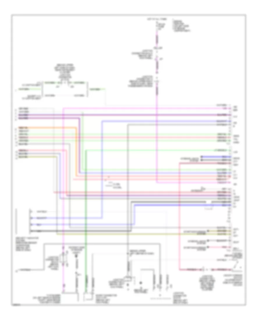
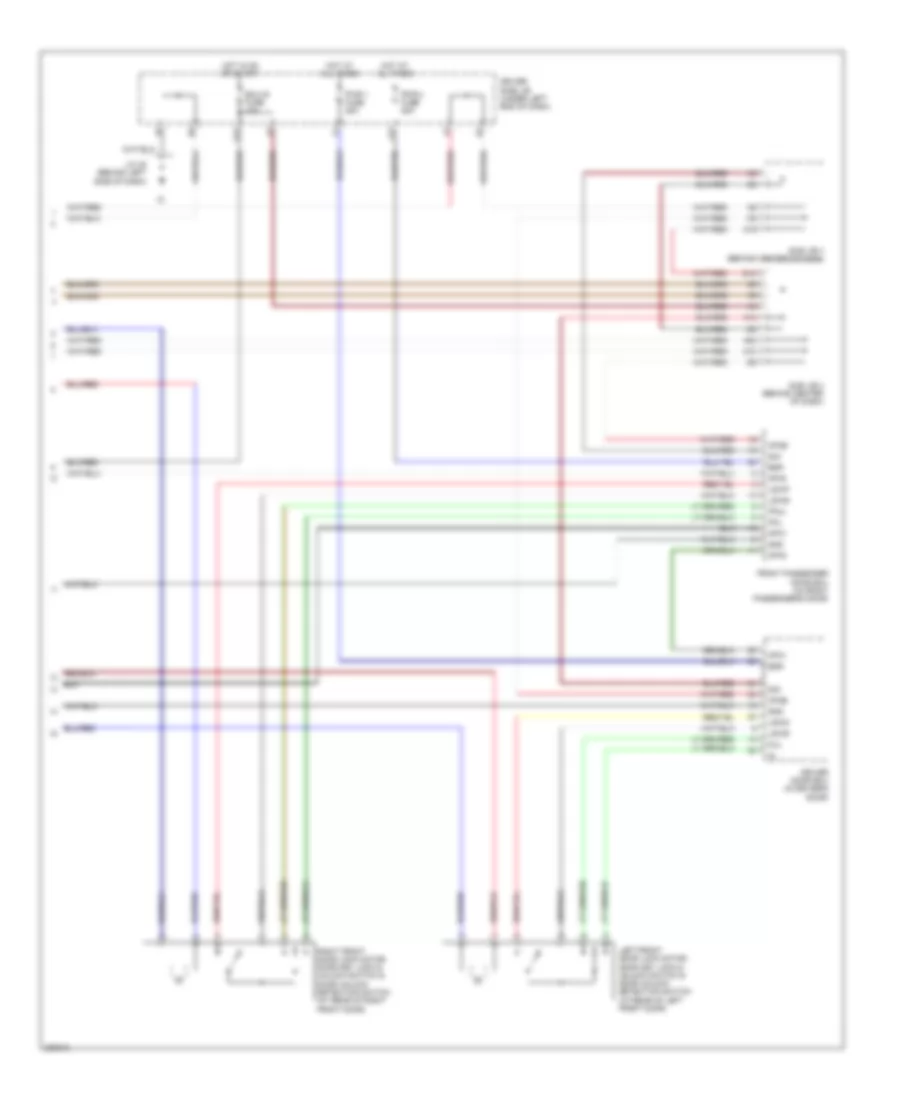
Power Door Locks Wiring Diagram, Access/Standard Cab with Keyless Entry (1 of 2) for Toyota Tundra SR5 2006
 https://portal-diagnostov.com/license.html
Automotive Electricians Portal FZCO
Automotive Electricians Portal FZCO
https://portal-diagnostov.com/license.html
https://portal-diagnostov.com/license.html
Automotive Electricians Portal FZCO
Automotive Electricians Portal FZCO
List of elements for Power Door Locks Wiring Diagram, Access/Standard Cab with Keyless Entry (1 of 2) for Toyota Tundra SR5 2006:
- (ends in harness)
- (in body harness, in left front door) b3
- Diode (w/o drl)
- Driver side j/b (behind lower left side of dash)
- Ecu ig fuse 5a
- G13
- Headlights system
- Horn fuse 10a
- Hot at all times
- Hot in on or start
- Integration relay
- J21
- Junction connector 10 (behind upper left side of dash, near instrument cluster)
- Junction connector 13 (behind right kick panel)
- Junction connector 21 & 22 (behind upper j22 left side of dash, near instrument cluster)
- Junction connector 4 (behind left kick panel)
- Junction connector 5 (behind upper left side of dash, near instrument cluster)
- Junction connector 7 (behind upper left side of dash, near instrument cluster)
- Junction connector 9 (behind upper left side of dash, near instrument cluster)
- L12
- L15
- Left door key lock & unlock lock switch
- Left door lock control unlk switch (power window master switch)
- Left door lock motor & door unlock detection switch (at rear of left front door)
- Lock
- N12
- N14
- Power fuse 30a
- Right door key lock & unlock unlk switch
- Right door lock control unlk switch
- Right door lock motor & door unlock detection switch (at rear of right front door)
- Tail fuse 15a
- Unlk
- W/ drl
- W/o drl
Power Door Locks Wiring Diagram, Access/Standard Cab with Keyless Entry (2 of 2) for Toyota Tundra SR5 2006
 https://portal-diagnostov.com/license.html
Automotive Electricians Portal FZCO
Automotive Electricians Portal FZCO
https://portal-diagnostov.com/license.html
https://portal-diagnostov.com/license.html
Automotive Electricians Portal FZCO
Automotive Electricians Portal FZCOList of elements for Power Door Locks Wiring Diagram, Access/Standard Cab with Keyless Entry (2 of 2) for Toyota Tundra SR5 2006:
- (behind left end of dash)
- (behind upper left center of dash) i2
- (behind upper left side of dash, near instrument cluster) junction connector 21 & 22
- (on right side of engine
- +b1
- +b2
- 4.7l w/ captain seat
- Act+
- Act-
- Antenna
- Bzr
- Compt) et
- Cty
- Dmlp
- Dswd
- E11
- Ecu-b fuse 5a
- Engine room r/b (on left side of engine compartment)
- Except 4.7l w/ captain seat
- Head
- Horn
- Hot at all times
- Ie (behind left kick panel)
- Ind
- Interior lights system
- J21
- J22
- J23
- J24
- J26
- J27
- Junction connector 12 (behind upper right side of dash, near passenger's air bag)
- Junction connector 23 & 24
- Junction connector 26 & 27 (behind left kick panel)
- Junction connector 3 (behind left kick panel)
- Junction connector 7 (behind upper left side of dash, near instrument cluster)
- Ksw
- Lswd
- Lswp
- Lug
- Mi+
- Mi-
- Nca
- Pnk
- Security indicator & glass breakage sensor microphone (behind left side of dash)
- Short connector (w/o tvip) (behind left kick panel)
- Srly
- Starting/charging system
- T11
- T12
- T13
- Tail
- Tvip buzzer (on left rear of engine compt, near brake master cylinder)
- Tvip ecu (behind center of dash)
- Ul1
- Ul2
- Ul3
- Unlock warning switch (in upper right side of steering column)
- W/ drl
- W/o drl
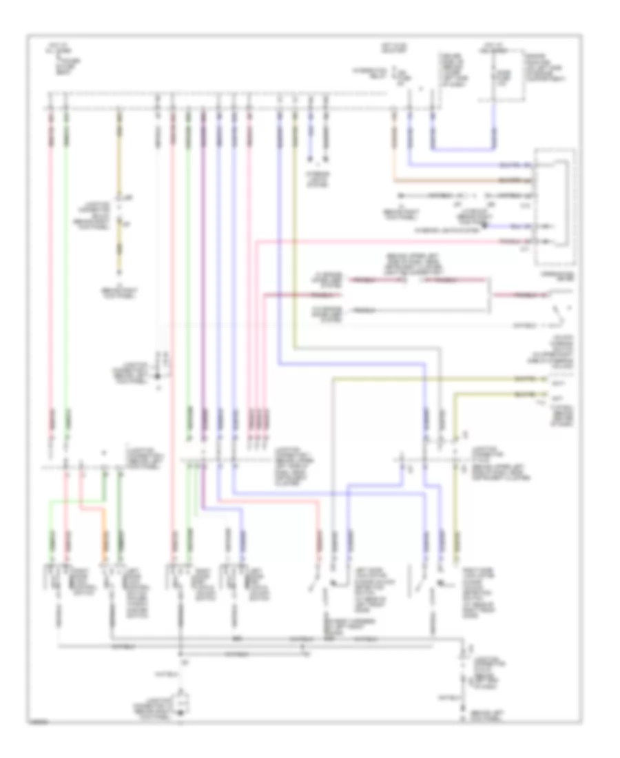
Power Door Locks Wiring Diagram, Access/Standard Cab withDRL, without Keyless Entry for Toyota Tundra SR5 2006
 https://portal-diagnostov.com/license.html
Automotive Electricians Portal FZCO
Automotive Electricians Portal FZCO
https://portal-diagnostov.com/license.html
https://portal-diagnostov.com/license.html
Automotive Electricians Portal FZCO
Automotive Electricians Portal FZCOList of elements for Power Door Locks Wiring Diagram, Access/Standard Cab withDRL, without Keyless Entry for Toyota Tundra SR5 2006:
- (behind left kick panel)
- (behind upper left side of dash, near instrument cluster)
- (behind upper left side of dash, near instrument cluster) junction connector 7
- (in body harness, in left front door) b3
- Act+
- Act-
- C11
- C12
- Combination meter
- Dome fuse 10a
- Driver side j/b (behind lower left side of dash)
- Engine room r/b (on left side of engine compartment)
- F10
- Hot at all times
- Hot in on or start
- Ign fuse 5a
- Ih (behind right kick panel)
- Integration relay
- Interior lights system
- J/c 66 & 67 (behind right kick panel)
- J21
- J22
- J23
- J24
- J66
- J67
- Junction connector 13 (behind right kick panel)
- Junction connector 21 & 22
- Junction connector 23 & 24 (behind left end of dash)
- Junction connector 3 (behind left kick panel)
- Junction connector 4 (behind left kick panel)
- Junction connector 66 & 67 (behind right kick panel)
- Junction connector 7 (behind upper left side of dash, near instrument cluster)
- Left door key lock & unlk unlock switch
- Left door lock control lock switch (power window master switch)
- Left door lock motor & door unlock detection switch (at rear of left front door)
- Lock
- N10
- N19
- N20
- N21
- N22
- N23
- N24
- Power fuse 30a
- Right door key lock & lock unlock switch
- Right door lock control unlk switch
- Right door lock motor & door unlock detection switch (at rear of right front door)
- T13
- Tvip ecu (behind center of dash)
- Unlk
- Unlock warning switch (in upper right side of steering column)
- W/ engine immobilizer system
- W/o engine immobilizer system
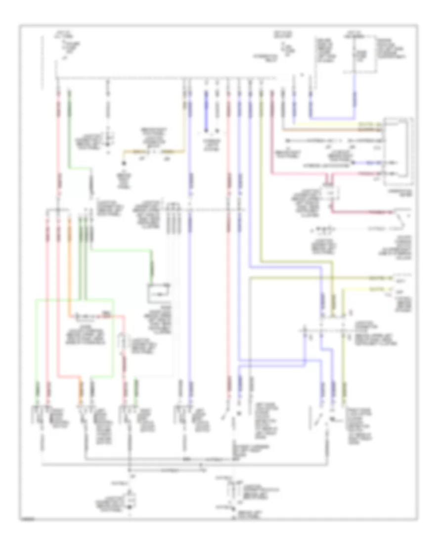
Power Door Locks Wiring Diagram, Access/Standard Cab without DRL, without Keyless Entry for Toyota Tundra SR5 2006
 https://portal-diagnostov.com/license.html
Automotive Electricians Portal FZCO
Automotive Electricians Portal FZCO
https://portal-diagnostov.com/license.html
https://portal-diagnostov.com/license.html
Automotive Electricians Portal FZCO
Automotive Electricians Portal FZCOList of elements for Power Door Locks Wiring Diagram, Access/Standard Cab without DRL, without Keyless Entry for Toyota Tundra SR5 2006:
- (behind left kick panel) ie
- (behind right kick panel) junction connector 66 & 67
- (behind upper left side of dash, near instrument cluster)
- (in body harness, in left front door) b3
- Acf
- Act+
- C11
- C12
- Combination meter
- Diode (door lock) (behind upper left side of dash, near instrument cluster)
- Diode (unlock warning) (behind upper left end of dash, near base of windshield)
- Dome fuse 10a
- Driver side j/b (behind lower left side of dash)
- Engine room r/b (on left side of engine compartment)
- F10
- Hot at all times
- Hot in on or start
- Ign fuse 5a
- Ih (behind right kick panel)
- Integration relay
- Interior lights system
- J/c 66 & 67 (behind right kick panel)
- J21
- J22
- J23
- J24
- J66
- J67
- Junction connector 13 (behind right kick panel)
- Junction connector 21 & 22
- Junction connector 23 & 24 (behind left end of dash)
- Junction connector 3 (behind left kick panel)
- Junction connector 4 (behind left kick panel)
- Junction connector 7 (behind upper left side of dash, near instrument cluster)
- L16
- Left door key lock & unlk unlock switch
- Left door lock control lock switch (power window master switch)
- Left door lock motor & door unlock detection switch (at rear of left front door)
- Lock
- Power fuse 30a
- Right door key lock & lock unlock switch
- Right door lock control unlk switch
- Right door lock motor & door unlock detection switch (at rear of right front door)
- T13
- Tvip ecu (behind center of dash)
- Unlk
- Unlock warning switch (in upper right side of steering column)
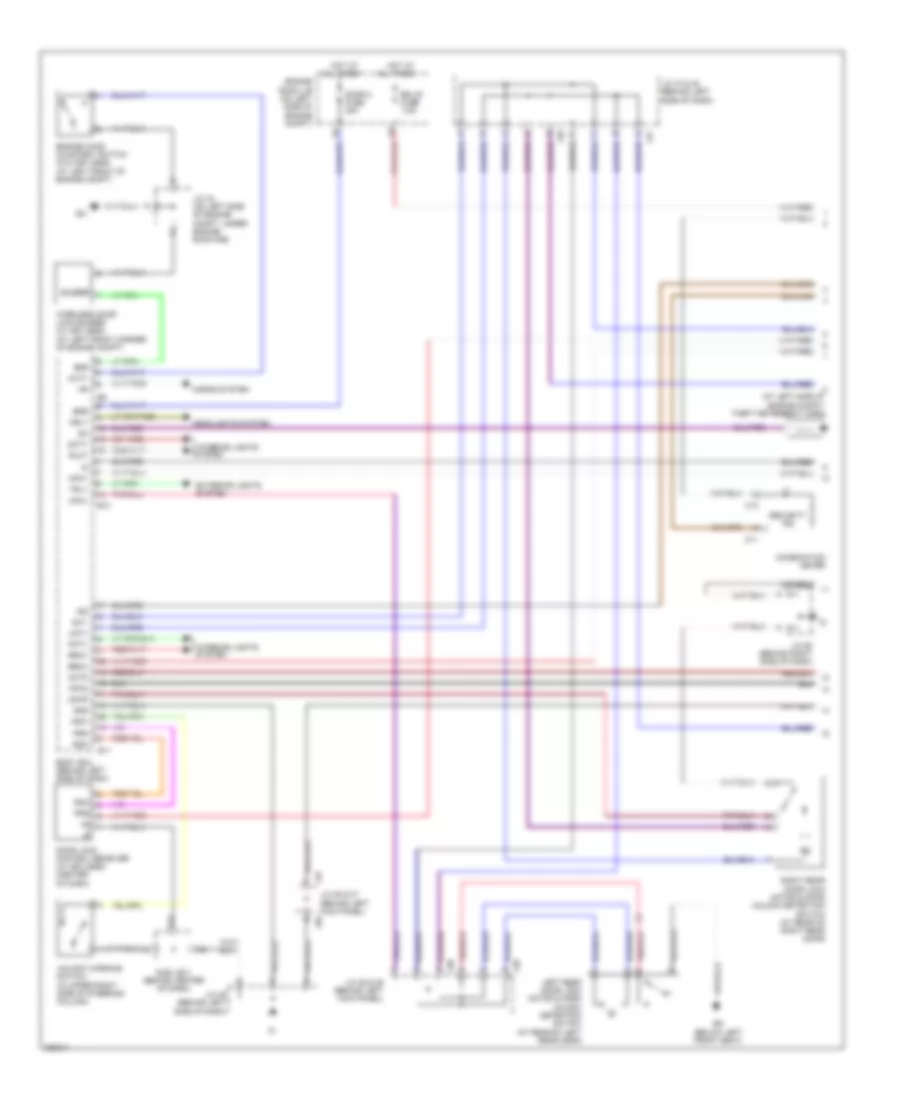
Power Door Locks Wiring Diagram, Double Cab (1 of 2) for Toyota Tundra SR5 2006
 https://portal-diagnostov.com/license.html
Automotive Electricians Portal FZCO
Automotive Electricians Portal FZCO
https://portal-diagnostov.com/license.html
https://portal-diagnostov.com/license.html
Automotive Electricians Portal FZCO
Automotive Electricians Portal FZCOList of elements for Power Door Locks Wiring Diagram, Double Cab (1 of 2) for Toyota Tundra SR5 2006:
- (at left side of engine compt) theft deterrent horn
- A12
- Act+
- Act-
- Actd
- All times
- B10
- B11
- Bdr
- Becu
- Body ecu (behind left side of dash)
- Bq (below left front seat)
- Buzzer
- Bzr
- C11
- C12
- Combination meter
- Dcty
- Door 2 fuse 30a
- Door lock control receiver (w/ keyless) (center of dash)
- Ecu b fuse 7.5a
- Engine hood courtesy switch (w/o keyless) (at left front of engine compt)
- Engine room j/b (on left side of engine compt)
- Exterior lights system
- Gnd
- Hcty
- Headlights system
- Horns system
- Hot at
- Hrly
- Ind
- Interior lights
- Interior lights system
- J/c 34 (on left side of engine compt, under engine room r/b)
- J/c 36 & 37 (behind left kick panel)
- J/c 38 & 39 (behind left kick panel)
- J/c 45 (behind left side of dash)
- J/c 47 & 48 (behind left side of dash)
- J/c 58 (behind right side of dash)
- J36
- J37
- J38
- J39
- J47
- J48
- Ksw
- Left rear door lock motor & door unlock detection switch (at rear of left rear door)
- Lswl
- Lswr
- Mpx1
- Mpx2
- Pcty
- Prg
- Rda
- Right rear door lock motor & door unlock detection switch (at rear of right rear door)
- Rlcy
- Rrcy
- Security ind
- Sub j/b 3 (behind center of dash)
- System
- Trly
- Unlock warning switch (in upper right side of steering column)
- Wireless door lock buzzer (w/ keyless) (at left front corner of engine compt)
Power Door Locks Wiring Diagram, Double Cab (2 of 2) for Toyota Tundra SR5 2006
 https://portal-diagnostov.com/license.html
Automotive Electricians Portal FZCO
Automotive Electricians Portal FZCO
https://portal-diagnostov.com/license.html
https://portal-diagnostov.com/license.html
Automotive Electricians Portal FZCO
Automotive Electricians Portal FZCOList of elements for Power Door Locks Wiring Diagram, Double Cab (2 of 2) for Toyota Tundra SR5 2006:
- A10
- A14
- A19
- A20
- Bdr
- Cpub
- D10
- Driver door ecu (in driver's door)
- Driver side j/b (under left end of dash)
- Ecu-ig fuse 10a
- F17
- Front passenger door ecu (in front passenger's door)
- G11
- Gnd
- Hot at all times
- Hot in on or start
- J/c 45 (behind left side of dash)
- Kul
- Left front door lock motor, door key lock & unlock switch & door unlock detection switch (at rear of left front door)
- Lswd
- Lswe
- Lswp
- Mpx1
- Mpx2
- Pkl
- Pkul
- Pwr 1 fuse 25a
- Pwr 2 fuse 25a
- Right front door lock motor, door key lock & unlock switch & door unlock detection switch (at rear of right front door)
- Sig
- Sub j/b 3 (behind center of dash)
- Sub j/b 4 (behind center of dash)

 Čeština
 Dansk
Dansk Deutsch
 Ελληνικά
 English
 English
 Español
 Suomi
Suomi Français
 Français
 עברית
עברית Hrvatski
 Magyar
 Italiano
 日本語
日本語 한국어
한국어 Nederlands
 Polski
 Português
 Português
 Română
 Русский
 Slovenčina
 Slovenščina
 Svenska
 Türkçe
