TRANSMISSION
2.4L
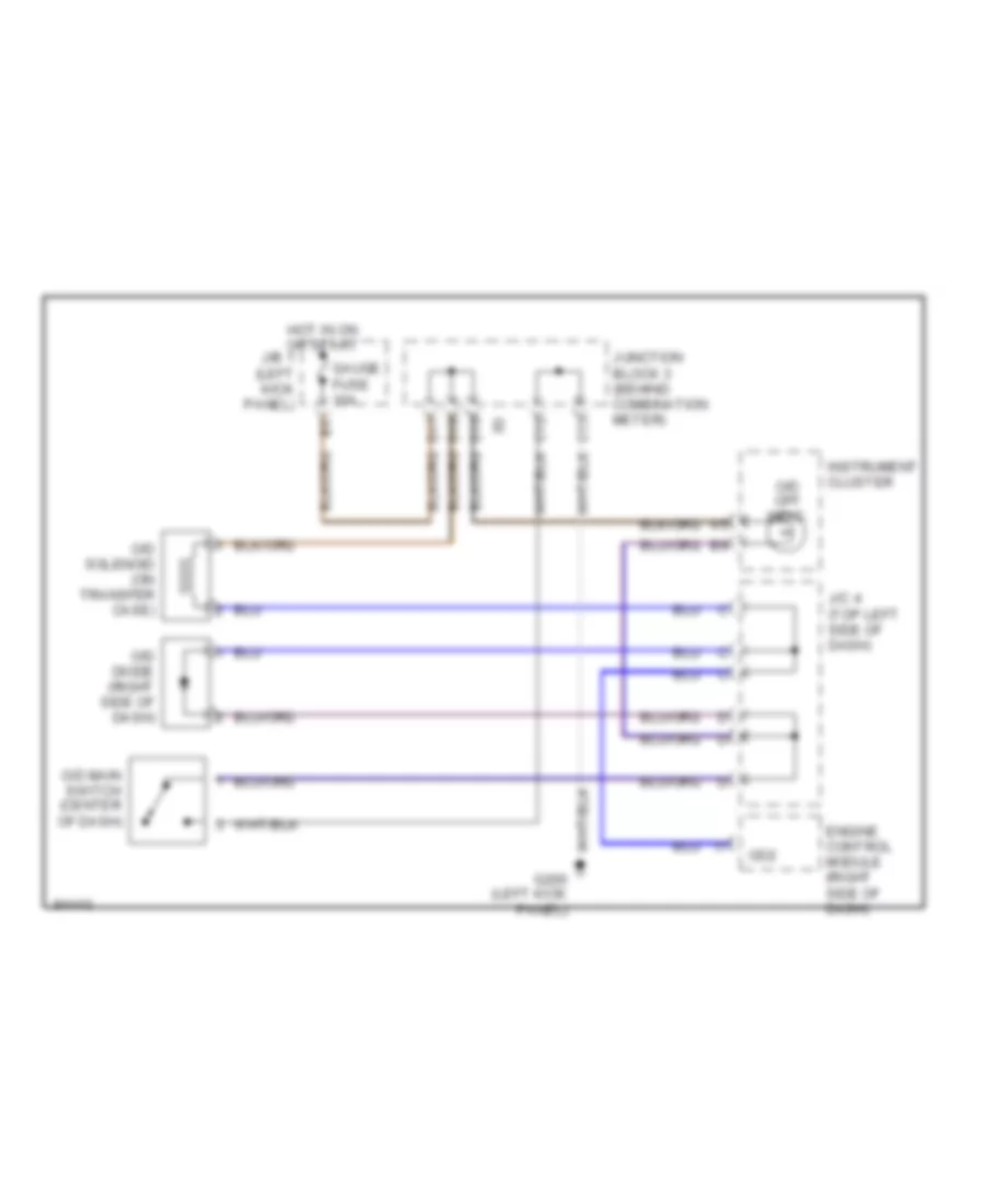
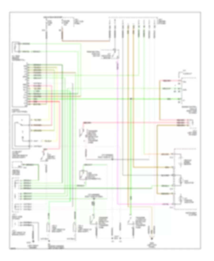
2.4L, Overdrive Wiring Diagram, 2WD for Toyota Tacoma SR5 1996
 https://portal-diagnostov.com/license.html
Automotive Electricians Portal FZCO
Automotive Electricians Portal FZCO
https://portal-diagnostov.com/license.html
https://portal-diagnostov.com/license.html
Automotive Electricians Portal FZCO
Automotive Electricians Portal FZCO
List of elements for 2.4L, Overdrive Wiring Diagram, 2WD for Toyota Tacoma SR5 1996:
- C12
- C13
- D16
- D17
- D19
- Engine control module (right side of dash)
- G200 (left kick panel)
- Gauge fuse 10a
- Hot in on or start
- Instrument cluster
- J/b 1 (left kick panel)
- J/c 4 (top left side of dash)
- Junction block 3 (behind combination meter)
- O/d diode (right side of dash)
- O/d main switch (center of dash)
- O/d off indic.
- O/d solenoid (on transfer case)
- Od2
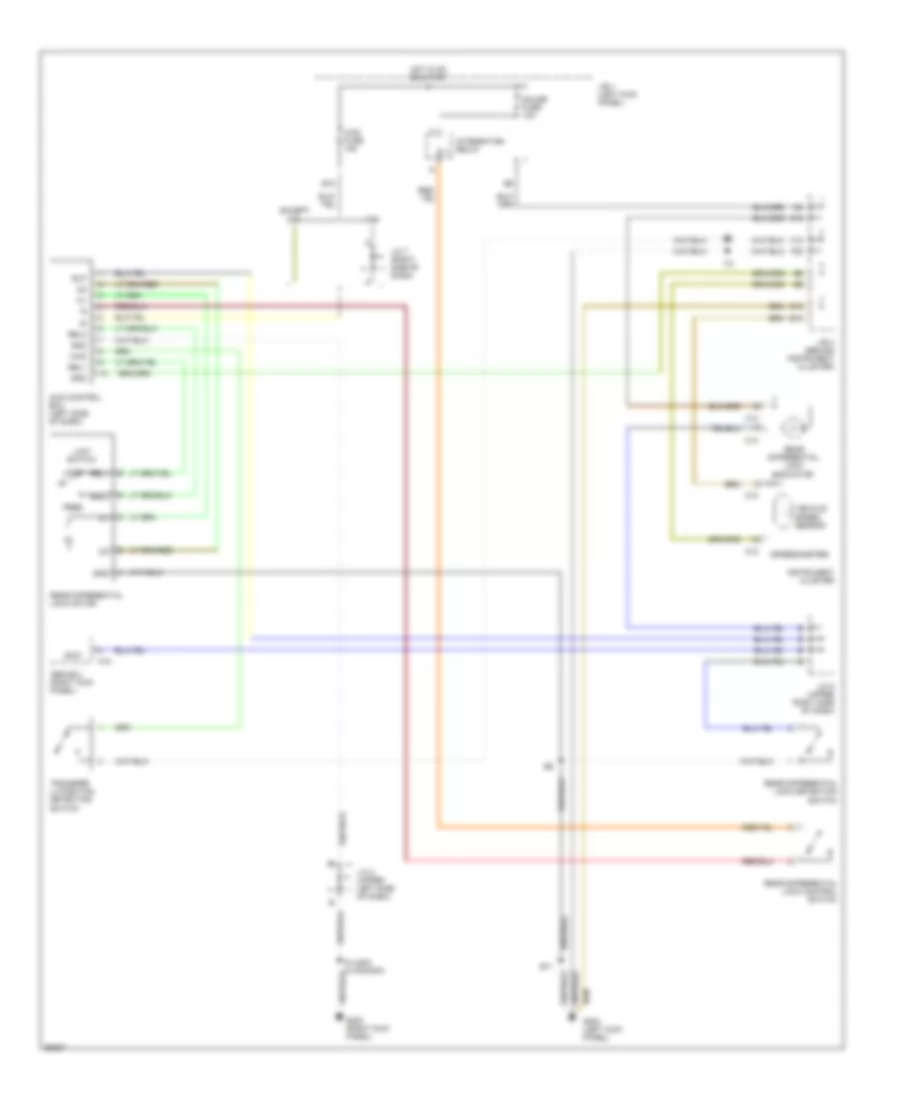
Rear Differential Lock Wiring Diagram for Toyota Tacoma SR5 1996
 https://portal-diagnostov.com/license.html
Automotive Electricians Portal FZCO
Automotive Electricians Portal FZCO
https://portal-diagnostov.com/license.html
https://portal-diagnostov.com/license.html
Automotive Electricians Portal FZCO
Automotive Electricians Portal FZCOList of elements for Rear Differential Lock Wiring Diagram for Toyota Tacoma SR5 1996:
- (speedometer)
- 3.4l
- 4wd
- 4wd control ecu (left side of dash)
- 4wd fuse 15a
- A10
- Abs ecu (right kick panel)
- B10
- B11
- B12
- C10
- C12
- C13
- D12
- D19
- Except 3.4l
- Exi2
- F18
- F20
- Free
- G200 (left kick panel)
- G203 (right kick panel)
- Gauge fuse 10a
- Gnd
- Hot in on or start
- I10
- I12
- I5 (usa) i4 canada)
- Instrument cluster
- Integration relay
- J/b 1 (left kick panel)
- J/b 3 (behind instrument cluster)
- J/c 2 (upper left side of dash)
- J/c 5 (upper right side of dash)
- J/c 7 (right side of dash)
- Limit switch
- Lock
- Rear differential lock control switch
- Rear differential lock detection switch
- Rear differential lock indicator
- Rear differential lock motor
- Rel1
- Rel2
- Rlp
- Spd
- Transfer l4 position detection switch
- Vehicle speed sensor
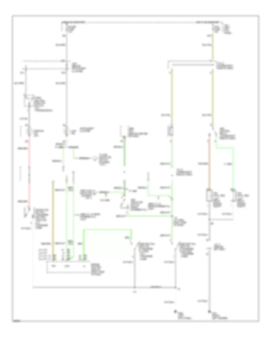
Transfer Case Wiring Diagram, with 2-4 Select Switch for Toyota Tacoma SR5 1996
 https://portal-diagnostov.com/license.html
Automotive Electricians Portal FZCO
Automotive Electricians Portal FZCO
https://portal-diagnostov.com/license.html
https://portal-diagnostov.com/license.html
Automotive Electricians Portal FZCO
Automotive Electricians Portal FZCOList of elements for Transfer Case Wiring Diagram, with 2-4 Select Switch for Toyota Tacoma SR5 1996:
- (i/p harness, right side of dash) i10
- (i/p harness, right side of i/p) i10
- (left front fender)
- 2-4
- 2-4 select motor (center rear of engine compt)
- 2-4 select switch
- 4wd
- 4wd ecu (left kick panel)
- 4wd fuse 15a
- 4wd indicator
- A/t indicator switch
- A/t parking indicator
- A10
- Abs ecu (center of dash)
- Add indicator switch (differential)
- C10
- C12
- C13
- D10
- D12
- D14
- D17
- D19
- E2 (engine harness, left of battery)
- Engine control module (right side of dash)
- Exi
- F18
- F20
- Floor a/t
- G100
- G200 (left kick panel)
- Gauge fuse 10a
- Grd
- Hot in run or start
- I10
- Ind
- Instrument cluster
- J/b 1 (left kick panel)
- J/b 3 (center of dash)
- J/c 1 (left front of engine compt)
- J/c 4 (left side of dash)
- J/c 7 (right side of dash)
- M/t
- Oil temp sensor (differential)
- Park/neutral position switch
- Red
- Rl1
- Rl2
- Spd
- Tfn
- Th+
- Th-
- Transfer l4 position detection switch (transfer case)
- Transfer neutral position detection switch (transfer case)
- Transfer position detection switch (transfer case)
- Vehicle speed sensor
- Vsv 2 (add) (left front of eng compt)
- Vsv 4 (add) (left front of eng compt)
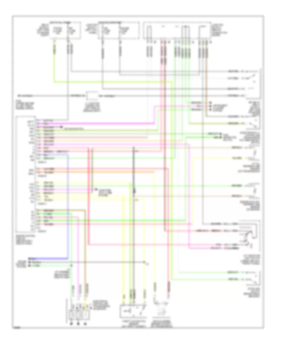
Transfer Case Wiring Diagram, without 2-4 Select Switch for Toyota Tacoma SR5 1996
 https://portal-diagnostov.com/license.html
Automotive Electricians Portal FZCO
Automotive Electricians Portal FZCO
https://portal-diagnostov.com/license.html
https://portal-diagnostov.com/license.html
Automotive Electricians Portal FZCO
Automotive Electricians Portal FZCOList of elements for Transfer Case Wiring Diagram, without 2-4 Select Switch for Toyota Tacoma SR5 1996:
- (a/t) (transfer case)
- (behind center of dash)
- (diagram 1 of 1)
- (left front engine compt)
- 1996 2.7l w/ rear differential lock
- 2.7l a/t
- 2.7l m/t
- 3.4l a/t
- 3.4l m/t
- 4wd
- 4wd fuse 15a
- 4wd ind
- Abs ecu
- Add control relay (lower right side of dash)
- Add indicator switch (front differential)
- B12
- D14
- D17
- D19
- Dectection switch (transfer 4wd pos) (transfer case)
- Dectection switch (transfer l4 pos) (a/t) (transfer case)
- Detection switch (transfer neutral position)
- Engine control module (right side of dash)
- Exi
- From 4wd indicator a
- G101 (front left fender)
- G200 (left kick panel)
- Gauge fuse 10a
- Hot in on or start
- I10
- I10 (i/p harn, right side of dash)
- Instrument cluster
- J/b 1 (left kick panel)
- J/b 3 (behind instrument cluster)
- J/c j1 (behind battery)
- J/c j7 (upper right side of dash)
- Park/ neutral position switch (a/t) (transmission)
- Parking ind (a/t)
- Tfn
- To add indicator switch (diagram 1 of 1)
- Vsv (2wd, add)
- Vsv (4wd, add)
- W/ abs
- W/o abs
2.7L
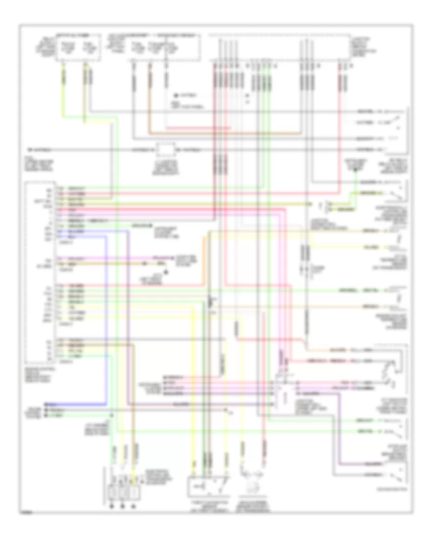
2.7L, Transmission Wiring Diagram for Toyota Tacoma SR5 1996
 https://portal-diagnostov.com/license.html
Automotive Electricians Portal FZCO
Automotive Electricians Portal FZCO
https://portal-diagnostov.com/license.html
https://portal-diagnostov.com/license.html
Automotive Electricians Portal FZCO
Automotive Electricians Portal FZCOList of elements for 2.7L, Transmission Wiring Diagram for Toyota Tacoma SR5 1996:
- (1996 only)
- (1996)
- 4wd
- 4wd detection switch
- A/t indicator light switch (under central trans tunnel)
- A/t oil temperature sensor (on transmission)
- Batt
- C11
- C12
- C13
- Computer data lines system
- Conn a
- Conn b
- Conn c
- Conn d
- Cruise control system
- D14
- D16
- D17
- Efi fuse 15a
- Efi relay (relay block 2, left side of engine compt)
- Electronic controlled transmission solenoids
- Electronically controlled transmission pattern select switch
- Engine control module (behind right side of dash)
- Engine coolant temperature sensor (on engine)
- F15
- G102 (upper center of left front fender apron)
- Gauge fuse 10a
- Hot at all times relay block 2 (left side of engine compt)
- Hot in on or start junction block 1 (left kick panel)
- I10
- I10 (i/p harness, behind right side of dash)
- Idl
- Ign fuse 7.5a
- Instrument cluster system
- J1 junction connector (left side of engine compt)
- Junction block 3 (behind combination meter)
- Nca
- No. 1
- No. 2
- No. 3
- O/d main switch
- Od1
- Od2
- Oil
- Oil-w
- Pnk
- Pwr
- Sp1
- Sp2+
- Sp2-
- Stop fuse 15a
- Stoplamp switch (brake pedal bracket)
- Te1
- Throttle position sensor (on throttle body)
- Thw
- Vcc
- Vehicle speed sensor (for ect) (on transmission)
- Vta
Rear Differential Lock Wiring Diagram for Toyota Tacoma SR5 1996
 https://portal-diagnostov.com/license.html
Automotive Electricians Portal FZCO
Automotive Electricians Portal FZCO
https://portal-diagnostov.com/license.html
https://portal-diagnostov.com/license.html
Automotive Electricians Portal FZCO
Automotive Electricians Portal FZCOList of elements for Rear Differential Lock Wiring Diagram for Toyota Tacoma SR5 1996:
- (speedometer)
- 3.4l
- 4wd
- 4wd control ecu (left side of dash)
- 4wd fuse 15a
- A10
- Abs ecu (right kick panel)
- B10
- B11
- B12
- C10
- C12
- C13
- D12
- D19
- Except 3.4l
- Exi2
- F18
- F20
- Free
- G200 (left kick panel)
- G203 (right kick panel)
- Gauge fuse 10a
- Gnd
- Hot in on or start
- I10
- I12
- I5 (usa) i4 canada)
- Instrument cluster
- Integration relay
- J/b 1 (left kick panel)
- J/b 3 (behind instrument cluster)
- J/c 2 (upper left side of dash)
- J/c 5 (upper right side of dash)
- J/c 7 (right side of dash)
- Limit switch
- Lock
- Rear differential lock control switch
- Rear differential lock detection switch
- Rear differential lock indicator
- Rear differential lock motor
- Rel1
- Rel2
- Rlp
- Spd
- Transfer l4 position detection switch
- Vehicle speed sensor
Transfer Case Wiring Diagram, with 2-4 Select Switch for Toyota Tacoma SR5 1996
 https://portal-diagnostov.com/license.html
Automotive Electricians Portal FZCO
Automotive Electricians Portal FZCO
https://portal-diagnostov.com/license.html
https://portal-diagnostov.com/license.html
Automotive Electricians Portal FZCO
Automotive Electricians Portal FZCOList of elements for Transfer Case Wiring Diagram, with 2-4 Select Switch for Toyota Tacoma SR5 1996:
- (i/p harness, right side of dash) i10
- (i/p harness, right side of i/p) i10
- (left front fender)
- 2-4
- 2-4 select motor (center rear of engine compt)
- 2-4 select switch
- 4wd
- 4wd ecu (left kick panel)
- 4wd fuse 15a
- 4wd indicator
- A/t indicator switch
- A/t parking indicator
- A10
- Abs ecu (center of dash)
- Add indicator switch (differential)
- C10
- C12
- C13
- D10
- D12
- D14
- D17
- D19
- E2 (engine harness, left of battery)
- Engine control module (right side of dash)
- Exi
- F18
- F20
- Floor a/t
- G100
- G200 (left kick panel)
- Gauge fuse 10a
- Grd
- Hot in run or start
- I10
- Ind
- Instrument cluster
- J/b 1 (left kick panel)
- J/b 3 (center of dash)
- J/c 1 (left front of engine compt)
- J/c 4 (left side of dash)
- J/c 7 (right side of dash)
- M/t
- Oil temp sensor (differential)
- Park/neutral position switch
- Red
- Rl1
- Rl2
- Spd
- Tfn
- Th+
- Th-
- Transfer l4 position detection switch (transfer case)
- Transfer neutral position detection switch (transfer case)
- Transfer position detection switch (transfer case)
- Vehicle speed sensor
- Vsv 2 (add) (left front of eng compt)
- Vsv 4 (add) (left front of eng compt)
Transfer Case Wiring Diagram, without 2-4 Select Switch for Toyota Tacoma SR5 1996
 https://portal-diagnostov.com/license.html
Automotive Electricians Portal FZCO
Automotive Electricians Portal FZCO
https://portal-diagnostov.com/license.html
https://portal-diagnostov.com/license.html
Automotive Electricians Portal FZCO
Automotive Electricians Portal FZCOList of elements for Transfer Case Wiring Diagram, without 2-4 Select Switch for Toyota Tacoma SR5 1996:
- (a/t) (transfer case)
- (behind center of dash)
- (diagram 1 of 1)
- (left front engine compt)
- 1996 2.7l w/ rear differential lock
- 2.7l a/t
- 2.7l m/t
- 3.4l a/t
- 3.4l m/t
- 4wd
- 4wd fuse 15a
- 4wd ind
- Abs ecu
- Add control relay (lower right side of dash)
- Add indicator switch (front differential)
- B12
- D14
- D17
- D19
- Dectection switch (transfer 4wd pos) (transfer case)
- Dectection switch (transfer l4 pos) (a/t) (transfer case)
- Detection switch (transfer neutral position)
- Engine control module (right side of dash)
- Exi
- From 4wd indicator a
- G101 (front left fender)
- G200 (left kick panel)
- Gauge fuse 10a
- Hot in on or start
- I10
- I10 (i/p harn, right side of dash)
- Instrument cluster
- J/b 1 (left kick panel)
- J/b 3 (behind instrument cluster)
- J/c j1 (behind battery)
- J/c j7 (upper right side of dash)
- Park/ neutral position switch (a/t) (transmission)
- Parking ind (a/t)
- Tfn
- To add indicator switch (diagram 1 of 1)
- Vsv (2wd, add)
- Vsv (4wd, add)
- W/ abs
- W/o abs
3.4L
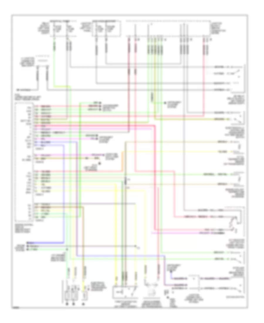
3.4L, Transmission Wiring Diagram, 2-Wheel Drive for Toyota Tacoma SR5 1996
 https://portal-diagnostov.com/license.html
Automotive Electricians Portal FZCO
Automotive Electricians Portal FZCO
https://portal-diagnostov.com/license.html
https://portal-diagnostov.com/license.html
Automotive Electricians Portal FZCO
Automotive Electricians Portal FZCOList of elements for 3.4L, Transmission Wiring Diagram, 2-Wheel Drive for Toyota Tacoma SR5 1996:
- (1996 only)
- A/t indicator light switch (under central trans tunnel)
- A/t oil temperature sensor (on transmission)
- Batt (b+)
- C12
- C13
- Cig fuse 15a
- Computer data lines system
- Conn a
- Conn b
- Conn c
- Conn d
- Cruise control system
- D13
- D16
- D17
- Diode (a/t)
- E1 (grd)
- E12
- E13
- Efi fuse 15a
- Efi relay (relay block 2, left side of engine compt)
- Electronic controlled transmission solenoids
- Electronically controlled transmission pattern select switch
- Engine control module (behind right side of dash)
- Engine coolant temperature sensor (on engine)
- F15
- G102 (upper center of left front fender apron)
- G110 (left front of engine)
- G200 (left kick panel)
- Gauge fuse 10a
- Hot at all times relay block 2 (left side of engine compt)
- Hot in accy or run
- Hot in run or start
- I10
- I10 (i/p harness, behind right side of dash)
- Idl
- Ign fuse 7.5a
- Instrument cluster system
- Instrument cluster system (vss)
- J1 junction connector (left side of engine compt)
- Junction block 1 (left kick panel)
- Junction block 3 (behind combination meter)
- Junction connector 4 (upper left end of dash)
- Junction connector 8 (right end of dash)
- Nca
- No. 1
- No. 2
- No. 3
- O/d main switch
- Od1
- Od2
- Oil
- Pnk
- Pwr
- Sp1
- Sp2+
- Sp2-
- Stop fuse 15a
- Stoplamp switch (brake pedal bracket)
- Te1
- Throttle position sensor (on throttle body)
- Thw
- Vcc
- Vehicle speed sensor (for ect) (on transmission)
- Vta
3.4L, Transmission Wiring Diagram, 4-Wheel Drive for Toyota Tacoma SR5 1996
 https://portal-diagnostov.com/license.html
Automotive Electricians Portal FZCO
Automotive Electricians Portal FZCO
https://portal-diagnostov.com/license.html
https://portal-diagnostov.com/license.html
Automotive Electricians Portal FZCO
Automotive Electricians Portal FZCOList of elements for 3.4L, Transmission Wiring Diagram, 4-Wheel Drive for Toyota Tacoma SR5 1996:
- (1996 only)
- (1996)
- 4wd
- 4wd engaged detection switch
- A/t indicator light switch (under central trans tunnel)
- A/t oil temperature sensor (on transmission)
- Batt (b+)
- C11
- C12
- C13
- Computer data lines system
- Conn a
- Conn b
- Conn c
- Conn d
- Cruise control system
- D14
- D16
- D17
- E1 (grd)
- E12
- E13
- Efi fuse 15a
- Efi relay (relay block 2, left side of engine compt)
- Electronic controlled transmission solenoids
- Electronically controlled transmission pattern select switch
- Engine control module (behind right side of dash)
- Engine coolant temperature sensor (on engine)
- F15
- G102 (upper center of left front fender apron)
- G110 (left front of engine)
- G200 (left kick panel)
- Gauge fuse 10a
- Hot at all times relay block 2 (left side of engine compt)
- Hot in run or start
- I10
- I10 (i/p harness, behind right side of dash)
- Idl
- Ign fuse 7.5a
- Instrument cluster system
- J1 junction connector (left side of eng compt)
- Junction block 1 (left kick panel)
- Junction block 3 (behind combination meter)
- Junction connector 4 (upper left end of dash)
- Nca
- No. 1
- No. 2
- No. 3
- O/d main switch
- Od1
- Od2
- Oil
- Oil-w
- Pnk
- Pwr
- Sp1
- Sp2+
- Sp2-
- Stop fuse 15a
- Stoplamp switch (brake pedal bracket)
- Te1
- Tfn
- Throttle position sensor (on throttle body)
- Thw
- Vcc
- Vehicle speed sensor (for ect) (on transmission)
- Vta
Rear Differential Lock Wiring Diagram for Toyota Tacoma SR5 1996
 https://portal-diagnostov.com/license.html
Automotive Electricians Portal FZCO
Automotive Electricians Portal FZCO
https://portal-diagnostov.com/license.html
https://portal-diagnostov.com/license.html
Automotive Electricians Portal FZCO
Automotive Electricians Portal FZCOList of elements for Rear Differential Lock Wiring Diagram for Toyota Tacoma SR5 1996:
- (speedometer)
- 3.4l
- 4wd
- 4wd control ecu (left side of dash)
- 4wd fuse 15a
- A10
- Abs ecu (right kick panel)
- B10
- B11
- B12
- C10
- C12
- C13
- D12
- D19
- Except 3.4l
- Exi2
- F18
- F20
- Free
- G200 (left kick panel)
- G203 (right kick panel)
- Gauge fuse 10a
- Gnd
- Hot in on or start
- I10
- I12
- I5 (usa) i4 canada)
- Instrument cluster
- Integration relay
- J/b 1 (left kick panel)
- J/b 3 (behind instrument cluster)
- J/c 2 (upper left side of dash)
- J/c 5 (upper right side of dash)
- J/c 7 (right side of dash)
- Limit switch
- Lock
- Rear differential lock control switch
- Rear differential lock detection switch
- Rear differential lock indicator
- Rear differential lock motor
- Rel1
- Rel2
- Rlp
- Spd
- Transfer l4 position detection switch
- Vehicle speed sensor
Transfer Case Wiring Diagram, with 2-4 Select Switch for Toyota Tacoma SR5 1996
 https://portal-diagnostov.com/license.html
Automotive Electricians Portal FZCO
Automotive Electricians Portal FZCO
https://portal-diagnostov.com/license.html
https://portal-diagnostov.com/license.html
Automotive Electricians Portal FZCO
Automotive Electricians Portal FZCOList of elements for Transfer Case Wiring Diagram, with 2-4 Select Switch for Toyota Tacoma SR5 1996:
- (i/p harness, right side of dash) i10
- (i/p harness, right side of i/p) i10
- (left front fender)
- 2-4
- 2-4 select motor (center rear of engine compt)
- 2-4 select switch
- 4wd
- 4wd ecu (left kick panel)
- 4wd fuse 15a
- 4wd indicator
- A/t indicator switch
- A/t parking indicator
- A10
- Abs ecu (center of dash)
- Add indicator switch (differential)
- C10
- C12
- C13
- D10
- D12
- D14
- D17
- D19
- E2 (engine harness, left of battery)
- Engine control module (right side of dash)
- Exi
- F18
- F20
- Floor a/t
- G100
- G200 (left kick panel)
- Gauge fuse 10a
- Grd
- Hot in run or start
- I10
- Ind
- Instrument cluster
- J/b 1 (left kick panel)
- J/b 3 (center of dash)
- J/c 1 (left front of engine compt)
- J/c 4 (left side of dash)
- J/c 7 (right side of dash)
- M/t
- Oil temp sensor (differential)
- Park/neutral position switch
- Red
- Rl1
- Rl2
- Spd
- Tfn
- Th+
- Th-
- Transfer l4 position detection switch (transfer case)
- Transfer neutral position detection switch (transfer case)
- Transfer position detection switch (transfer case)
- Vehicle speed sensor
- Vsv 2 (add) (left front of eng compt)
- Vsv 4 (add) (left front of eng compt)
Transfer Case Wiring Diagram, without 2-4 Select Switch for Toyota Tacoma SR5 1996
 https://portal-diagnostov.com/license.html
Automotive Electricians Portal FZCO
Automotive Electricians Portal FZCO
https://portal-diagnostov.com/license.html
https://portal-diagnostov.com/license.html
Automotive Electricians Portal FZCO
Automotive Electricians Portal FZCOList of elements for Transfer Case Wiring Diagram, without 2-4 Select Switch for Toyota Tacoma SR5 1996:
- (a/t) (transfer case)
- (behind center of dash)
- (diagram 1 of 1)
- (left front engine compt)
- 1996 2.7l w/ rear differential lock
- 2.7l a/t
- 2.7l m/t
- 3.4l a/t
- 3.4l m/t
- 4wd
- 4wd fuse 15a
- 4wd ind
- Abs ecu
- Add control relay (lower right side of dash)
- Add indicator switch (front differential)
- B12
- D14
- D17
- D19
- Dectection switch (transfer 4wd pos) (transfer case)
- Dectection switch (transfer l4 pos) (a/t) (transfer case)
- Detection switch (transfer neutral position)
- Engine control module (right side of dash)
- Exi
- From 4wd indicator a
- G101 (front left fender)
- G200 (left kick panel)
- Gauge fuse 10a
- Hot in on or start
- I10
- I10 (i/p harn, right side of dash)
- Instrument cluster
- J/b 1 (left kick panel)
- J/b 3 (behind instrument cluster)
- J/c j1 (behind battery)
- J/c j7 (upper right side of dash)
- Park/ neutral position switch (a/t) (transmission)
- Parking ind (a/t)
- Tfn
- To add indicator switch (diagram 1 of 1)
- Vsv (2wd, add)
- Vsv (4wd, add)
- W/ abs
- W/o abs

 Čeština
 Dansk
Dansk Deutsch
 Ελληνικά
 English
 English
 Español
 Suomi
Suomi Français
 Français
 עברית
עברית Hrvatski
 Magyar
 Italiano
 日本語
日本語 한국어
한국어 Nederlands
 Polski
 Português
 Português
 Română
 Русский
 Slovenčina
 Slovenščina
 Svenska
 Türkçe
