Čeština
 Dansk
Dansk Deutsch
 Ελληνικά
 English
 English
 Español
 Suomi
Suomi Français
 Français
 עברית
עברית Hrvatski
 Magyar
 Italiano
 日本語
日本語 한국어
한국어 Nederlands
 Polski
 Português
 Português
 Română
 Русский
 Slovenčina
 Slovenščina
 Svenska
 Türkçe

Audi allroad Quattro 2005 - 2000-2004 ENGINE 2.7L V6 5V Biturbo (APB, BEL) - A6 & Allroad
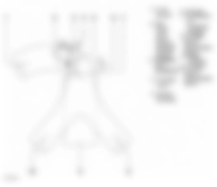
Audi allroad Quattro 2005 - Technical data VIN number
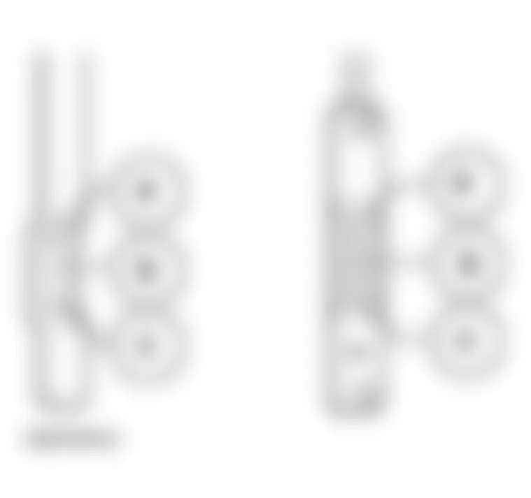
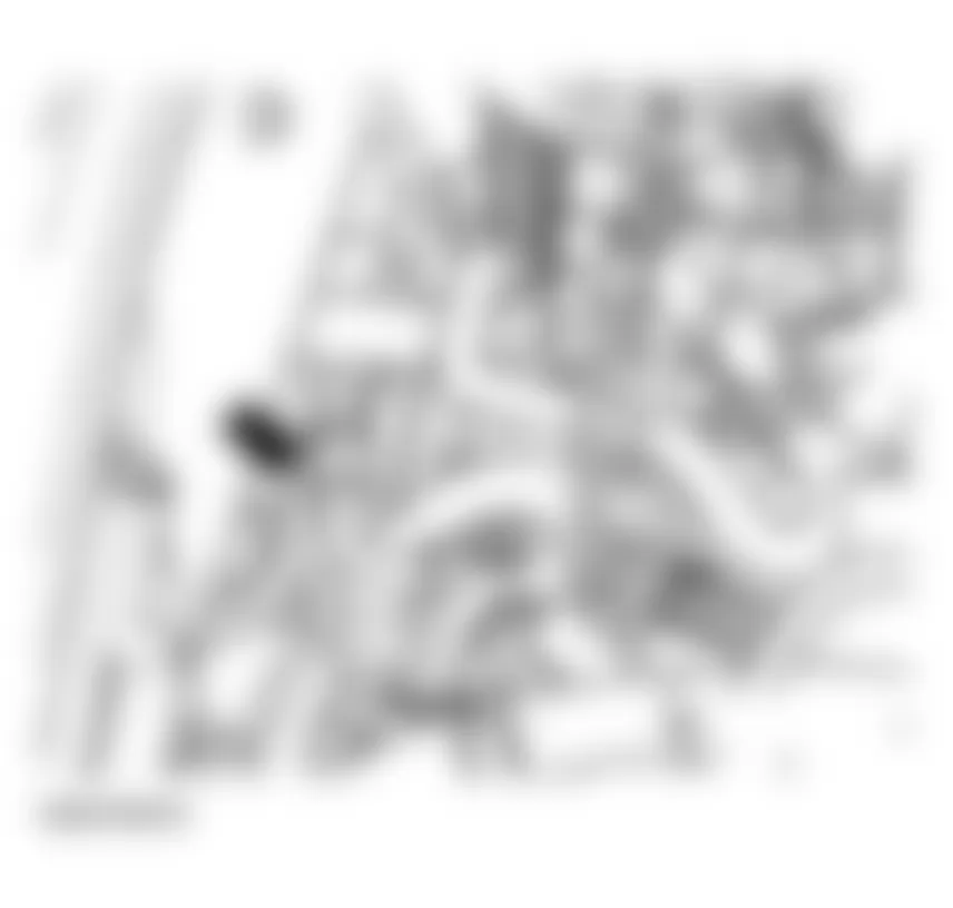
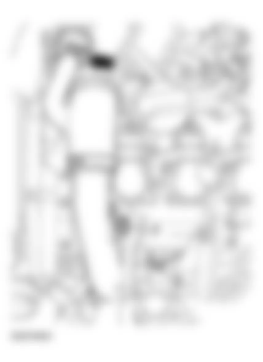
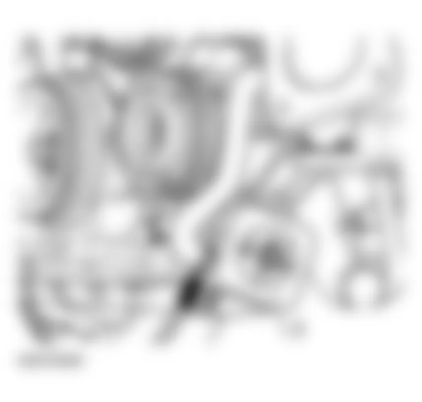
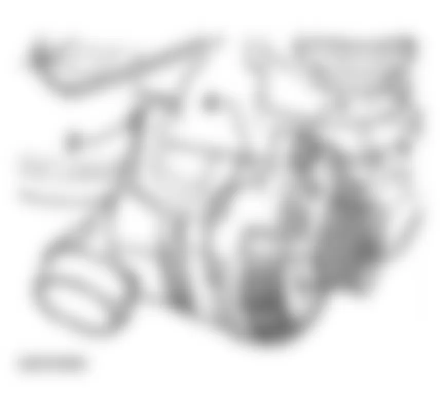
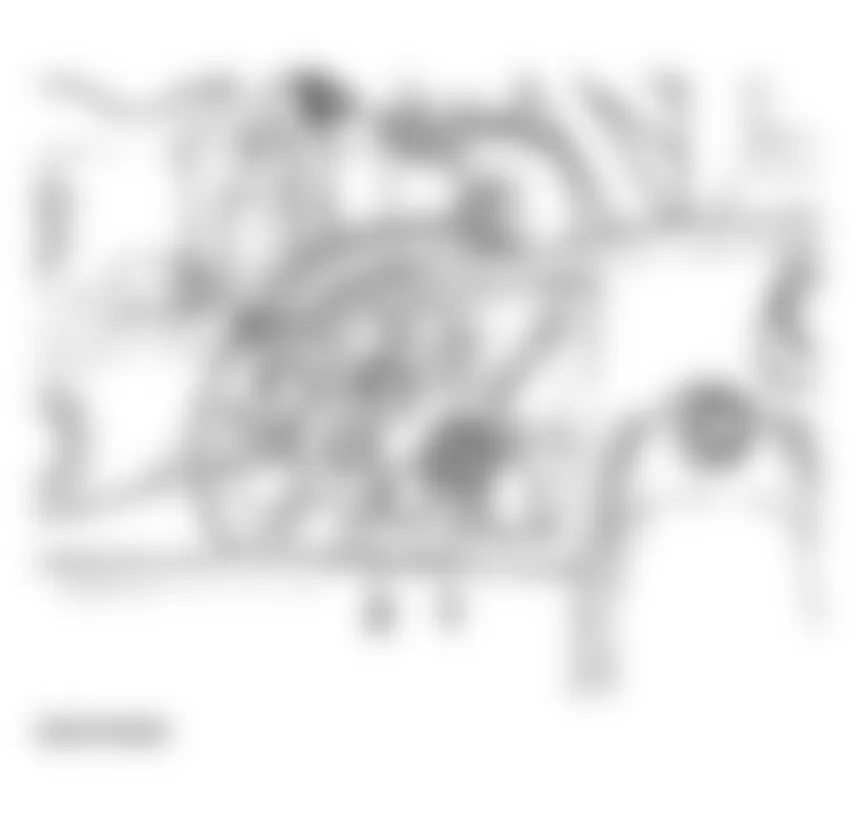
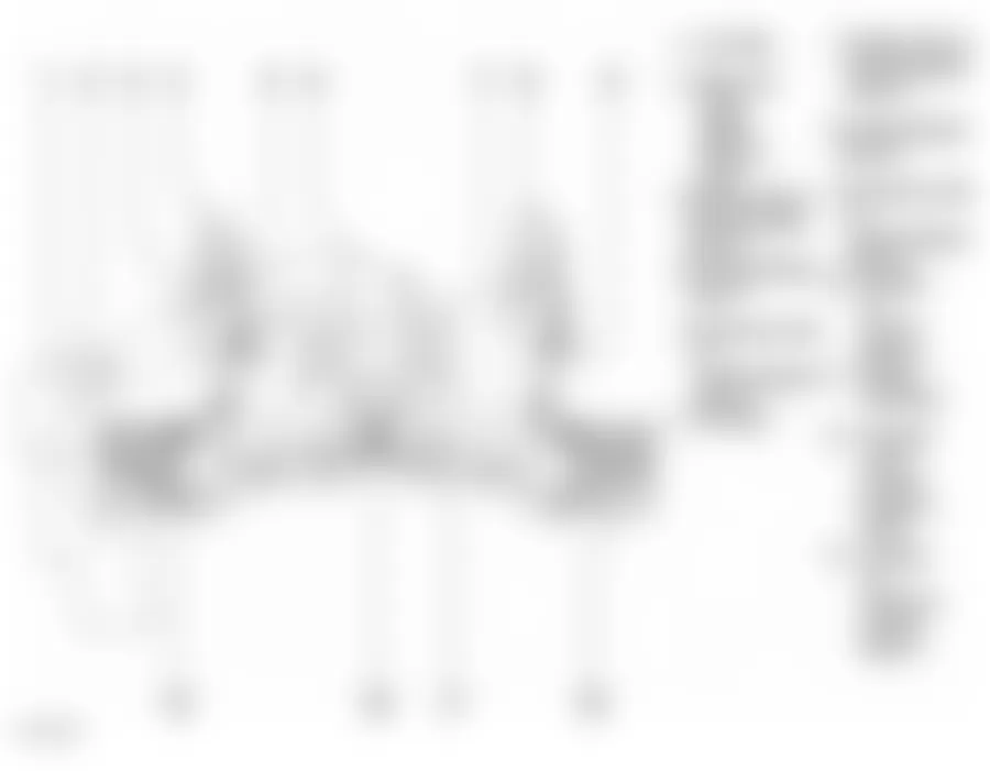
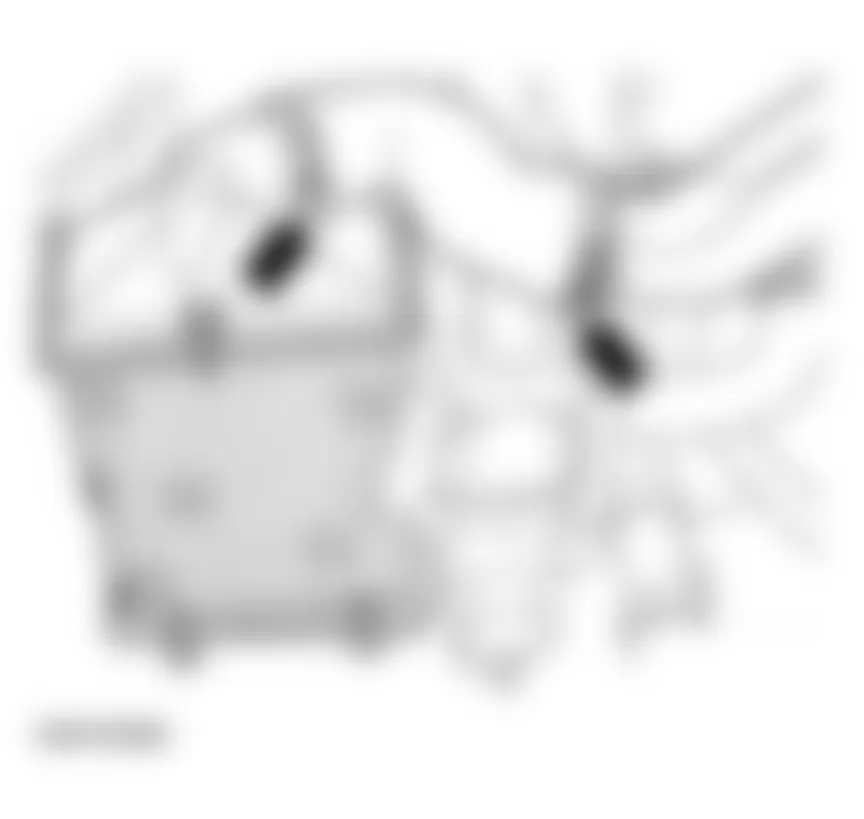
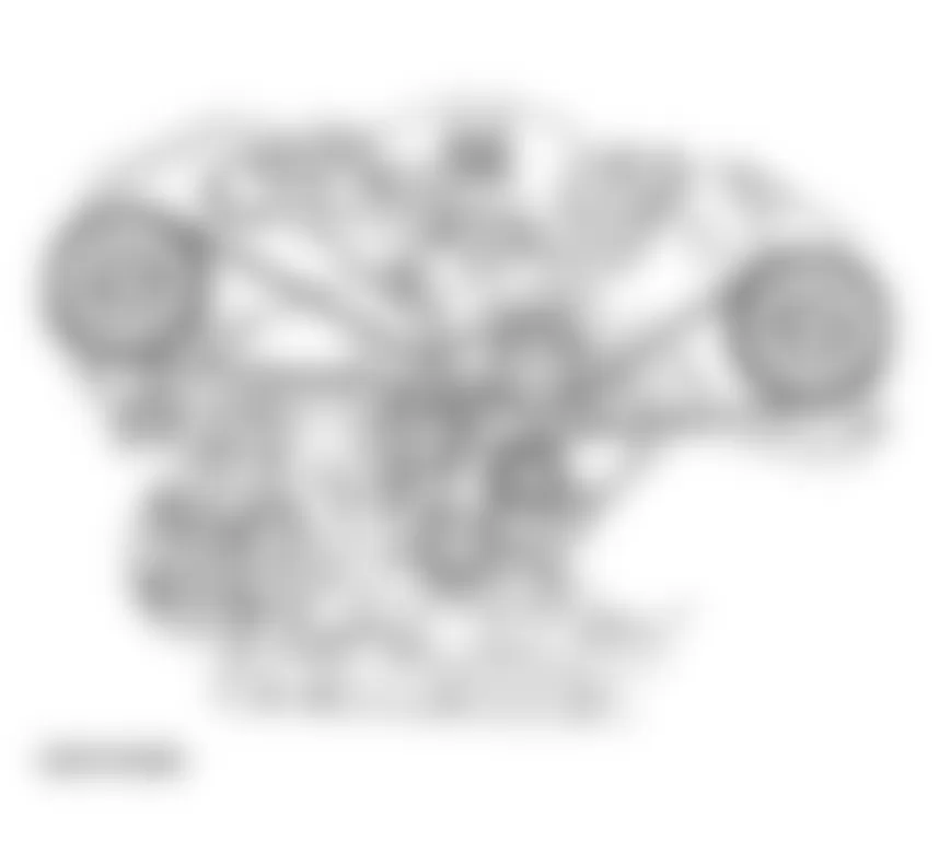
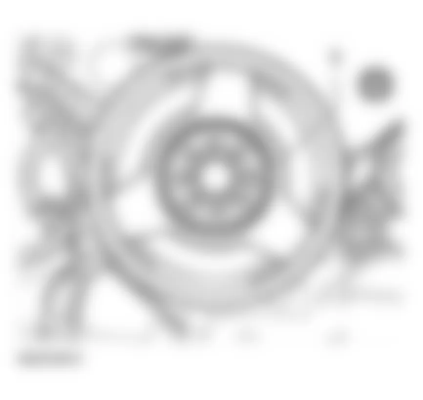
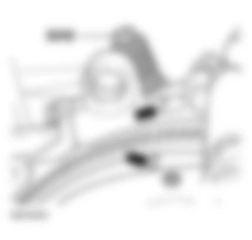
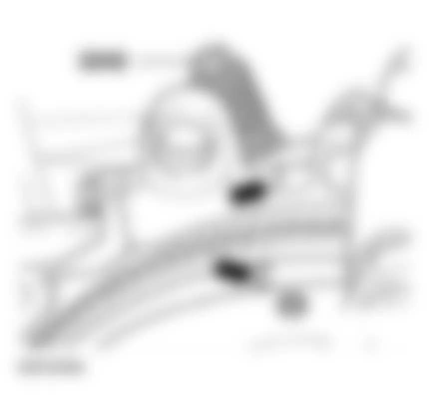
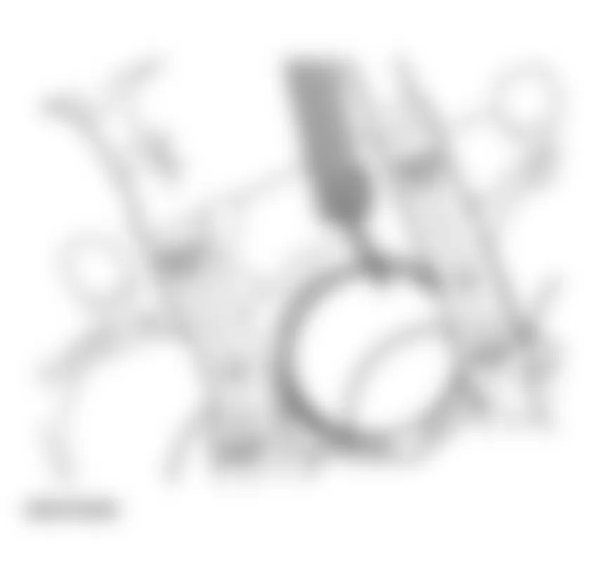
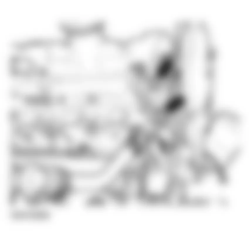
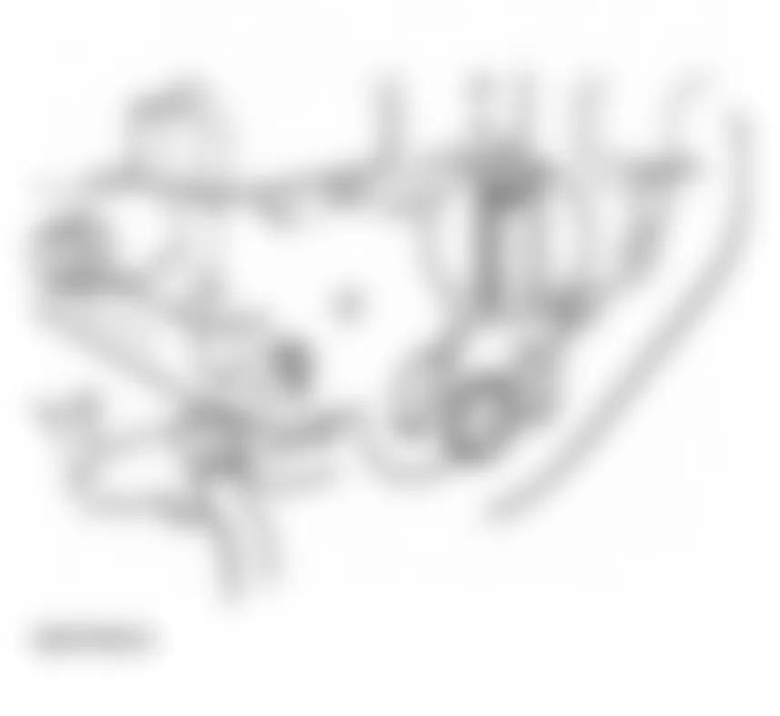
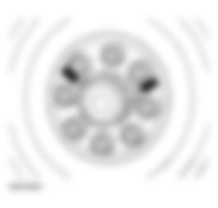
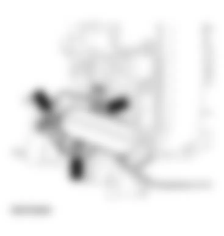
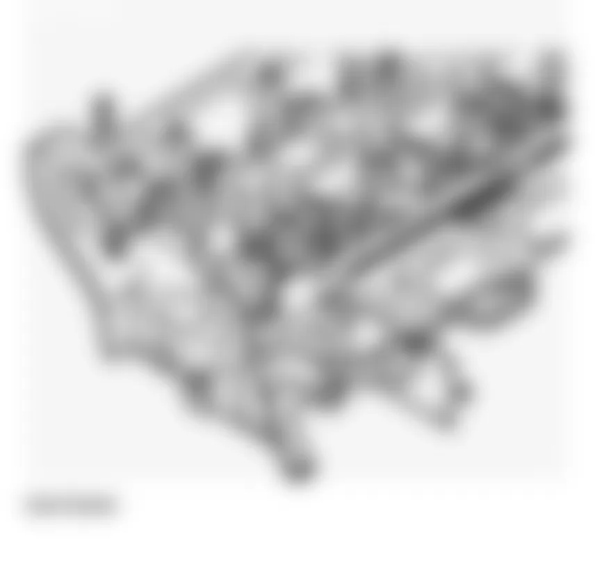
The VIN number (engine code and serial number) is on the machined surface on the cylinder block, at the front of the right cylinder bank.
The engine code is also indicated on the vehicle data sticker.


Fig. 1: Audi allroad Quattro 2005 - Component Locations - Identifying VIN Number
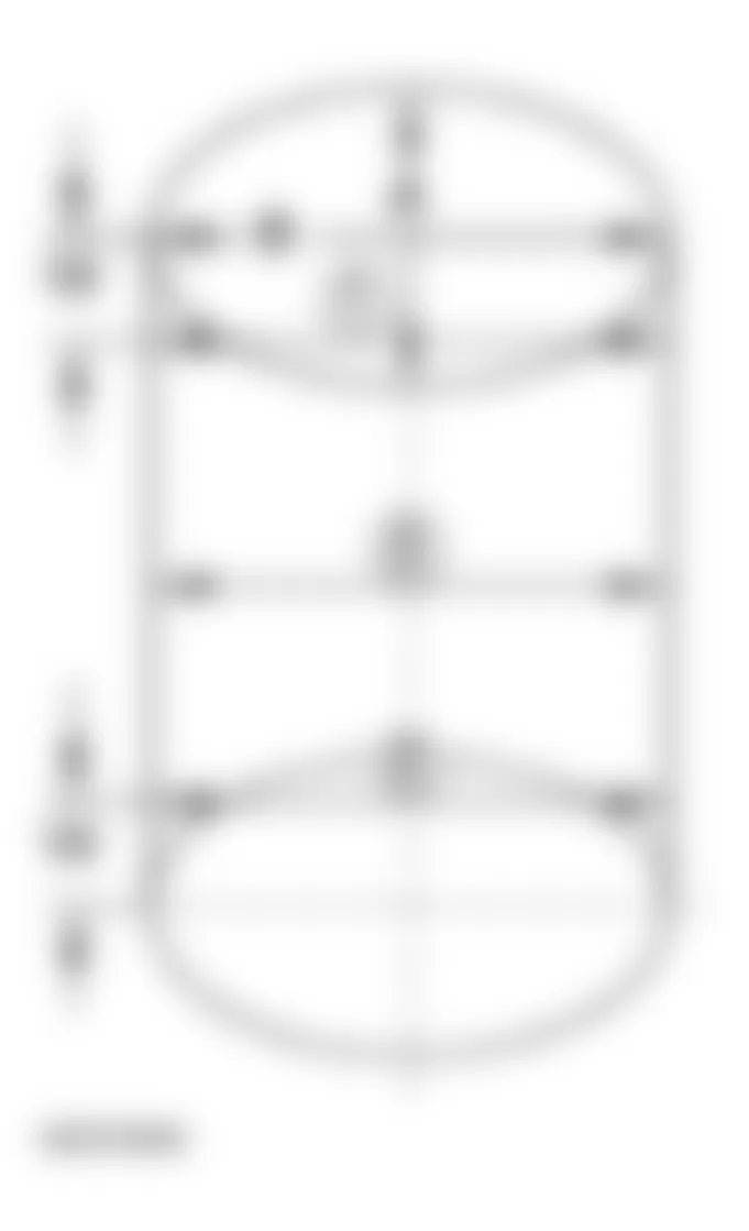
Audi allroad Quattro 2005 - Engine data
Fig. 2: Audi allroad Quattro 2005 - Component Locations - Engine Data Chart (1 Of 2)
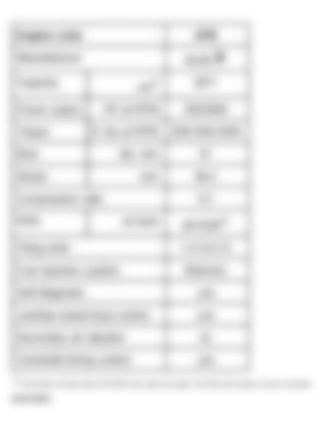
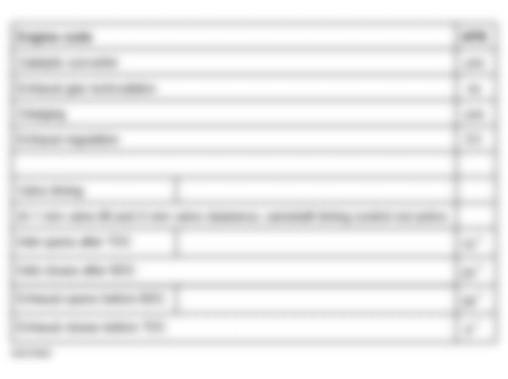
1 ) Fuel with not less than 95 RON can also be used, but this will cause a loss of power.
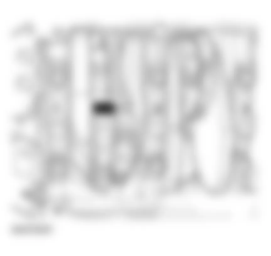
Fig. 3: Audi allroad Quattro 2005 - Component Locations - Engine Data Chart (2 Of 2)
Audi allroad Quattro 2005 - Engine - Assembly Engine, removing and installing
CAUTION: Before beginning repairs on the electrical system:
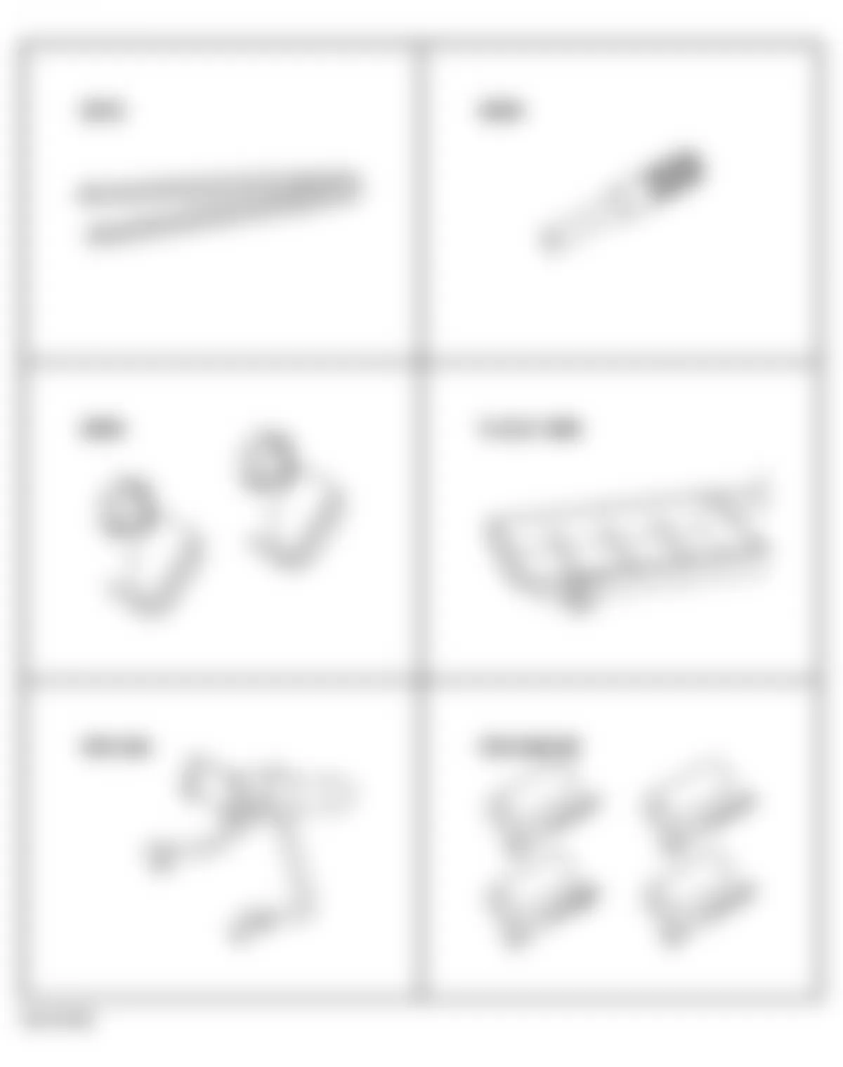
Audi allroad Quattro 2005 - Engine, removing and installing Special tools and equipment
- Special tool 3204
- Special tool 3212
- VAG 1306
- Special tool 3094
- Special tool VW 540
- Special tool VW 540/1B
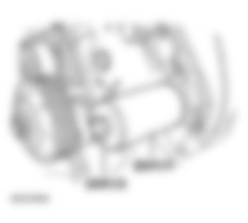
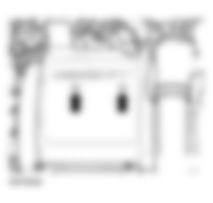
Fig. 4: Audi allroad Quattro 2005 - Component Locations - Engine Removing Special Tool (1 Of 2) - Special tool 10-222A and 10-222A/1 and 0-222A/3
- Special tool 2024 A
- VAG 1202 A
- VAG 1331
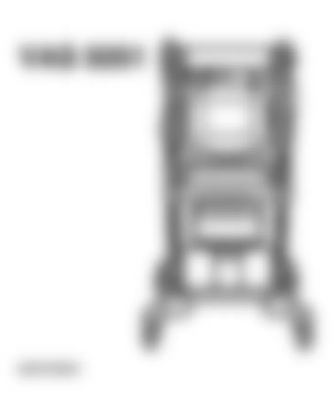
Fig. 5: Audi allroad Quattro 2005 - Component Locations - Engine Removing Special Tool (2 Of 2)
Audi allroad Quattro 2005 - Engine, removing
NOTE:
See Caution before beginning repairs on the electrical system under ENGINE, REMOVING AND INSTALLING.
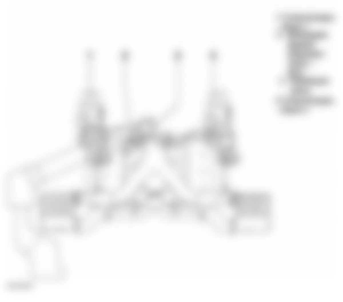
- Remove plenum cover.
- Switch ignition off and disconnect battery Ground (GND) strap.
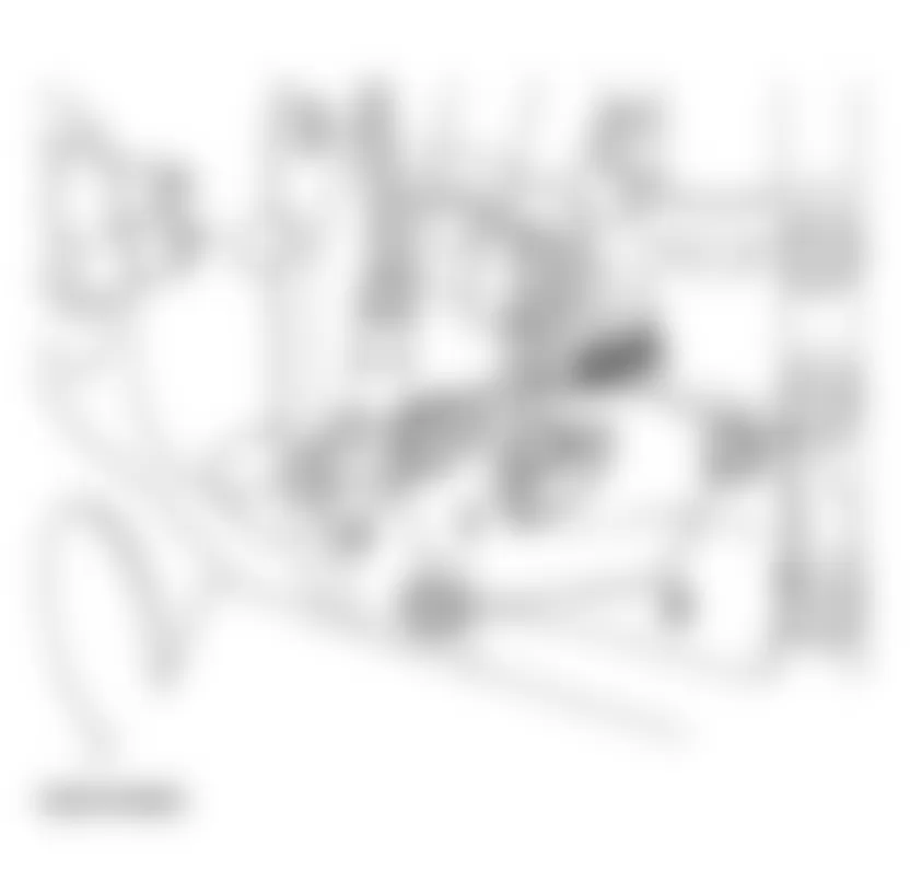
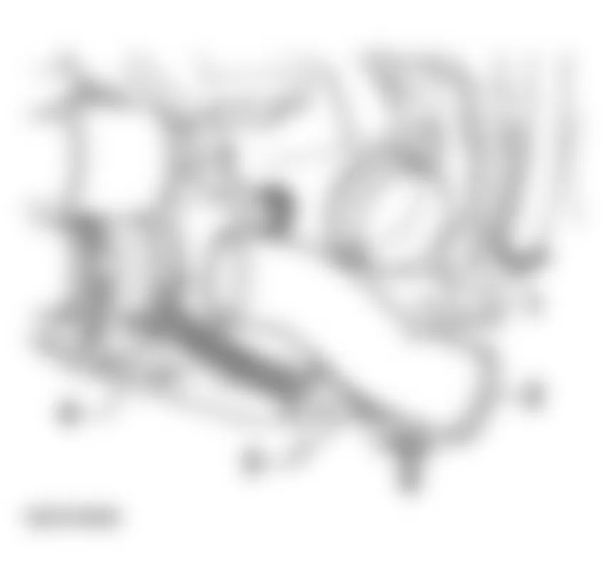
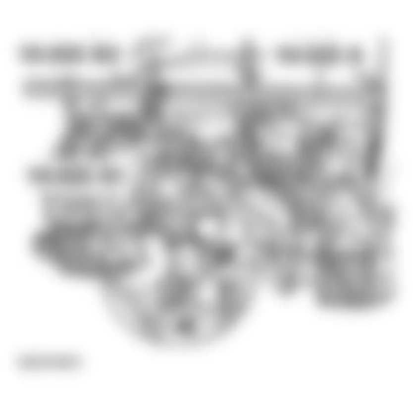
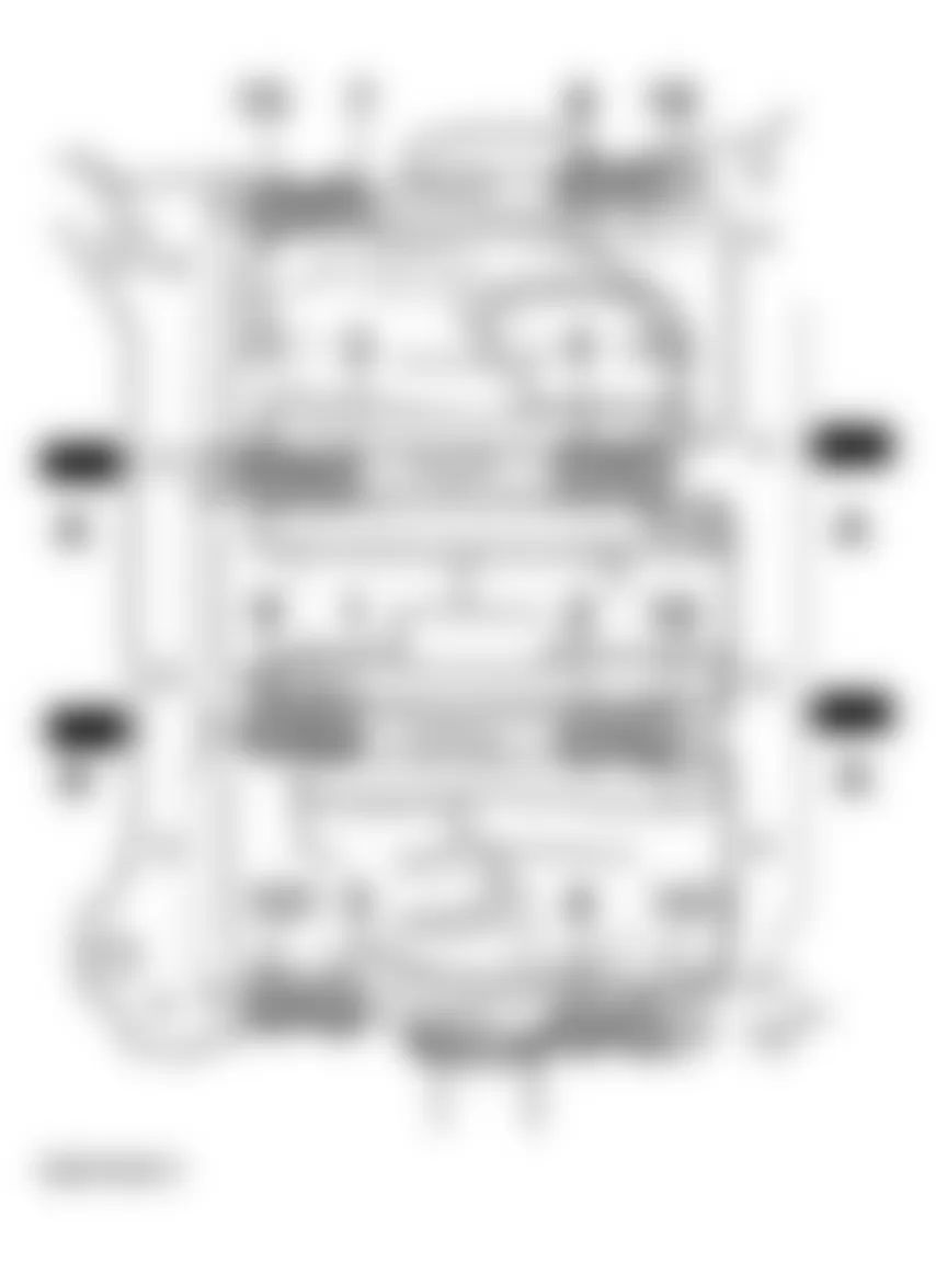
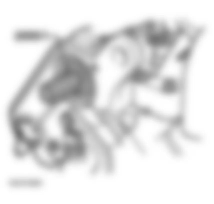
- Remove bolts (arrows) and remove engine covers -A- and -C-.
- Remove cover above air filter.
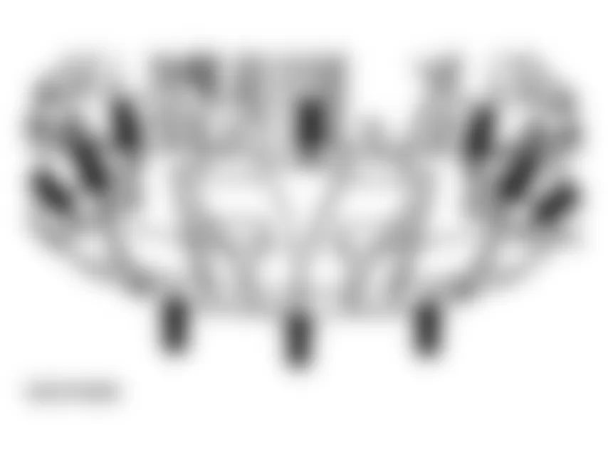
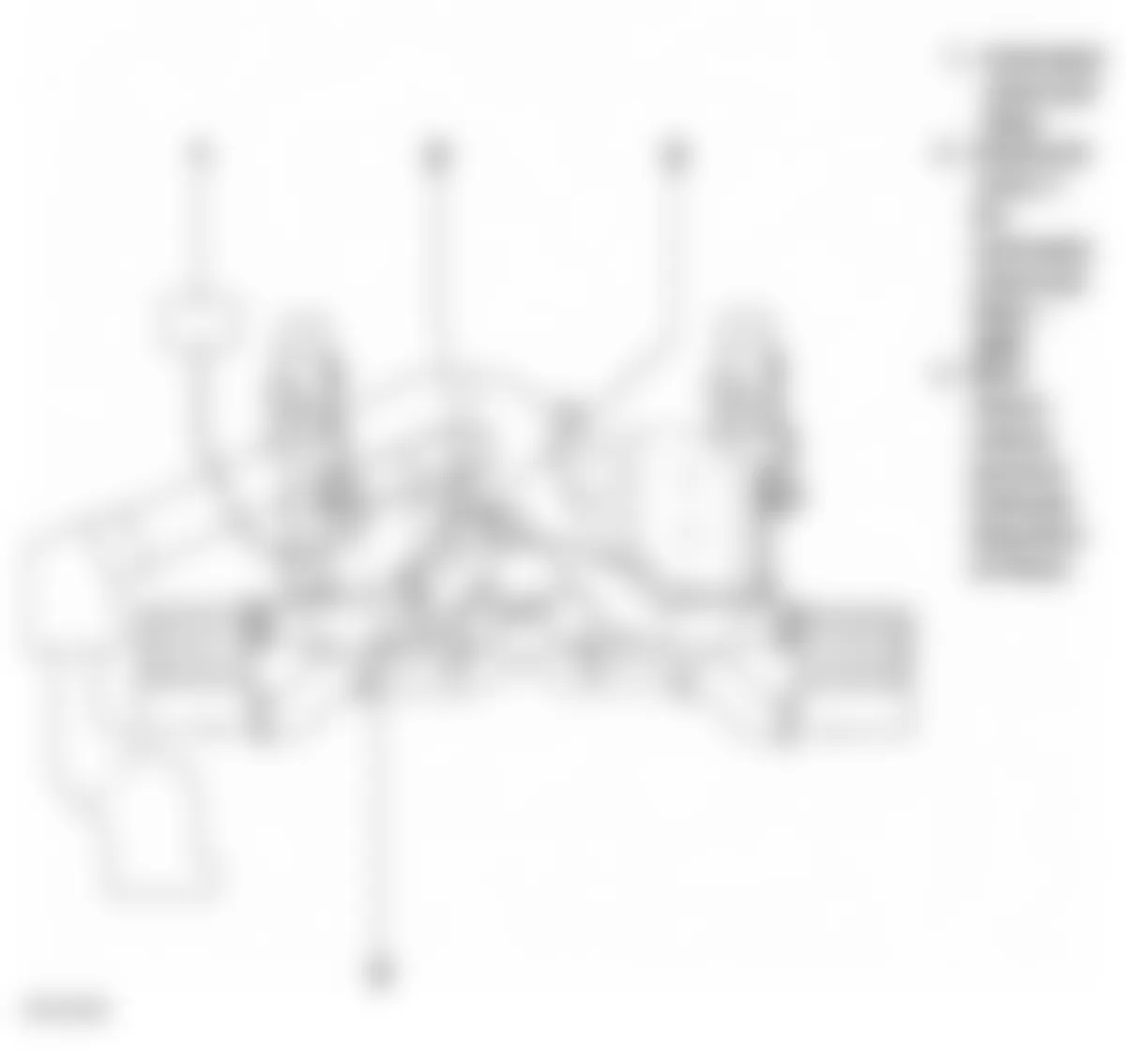
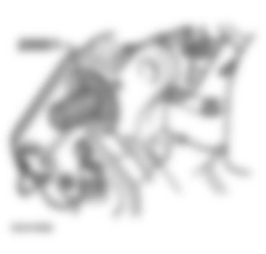
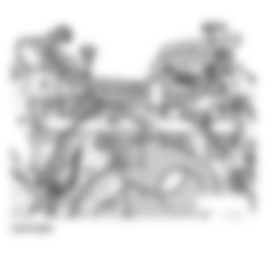
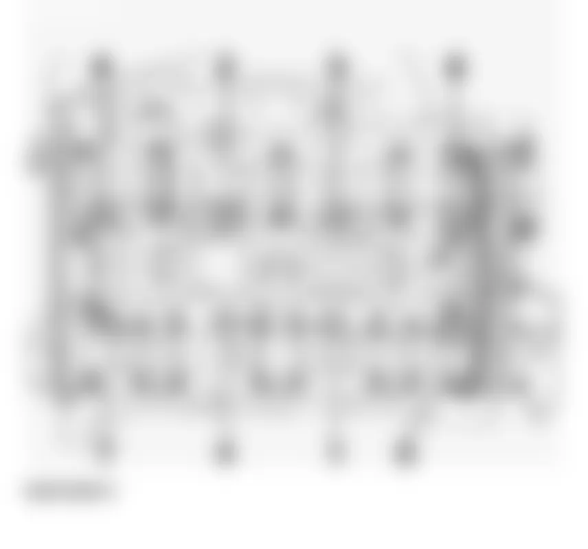
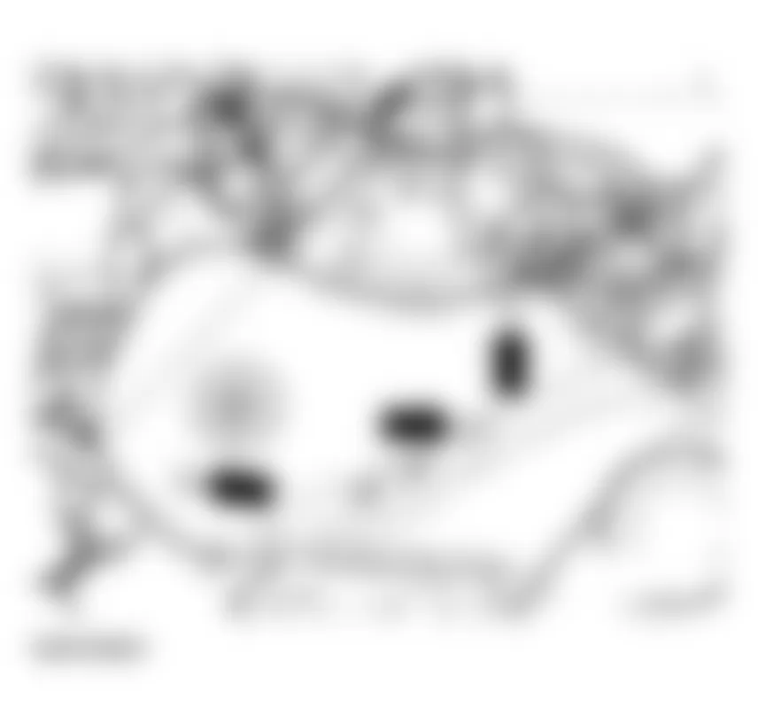
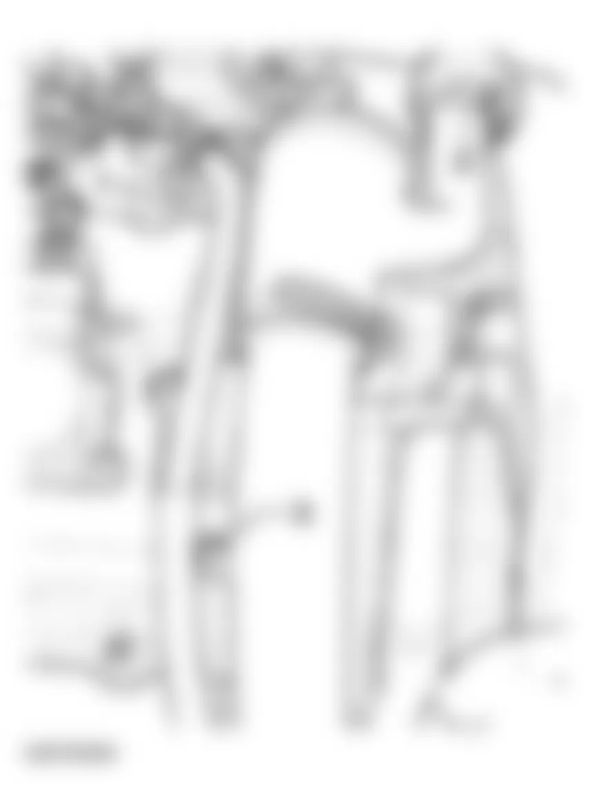
Fig. 6: Audi allroad Quattro 2005 - Component Locations - Removing Engine Covers - Remove sound-proofing material (arrows).
- Remove bracket for sound-proofing at unit support.
- Drain engine coolant. See COOLING SYSTEM, DRAINING AND FILLING .
- Remove bumper:
See FRONT BUMPER .
- Remove lock carrier:
LOCK CARRIER WITH ATTACHMENTS, REMOVING AND INSTALLING .
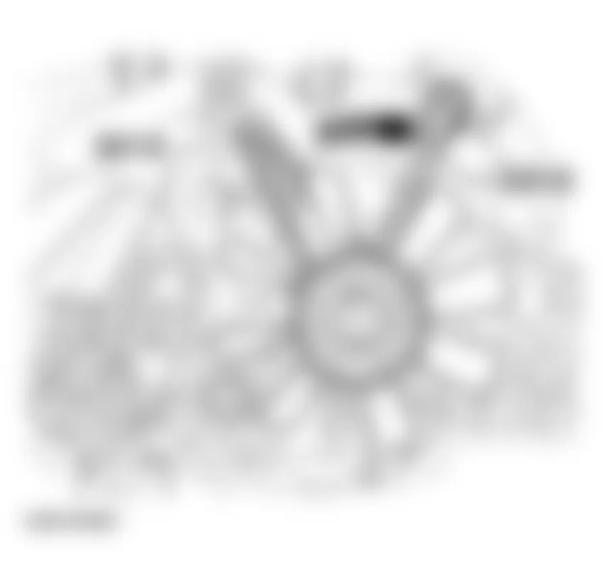
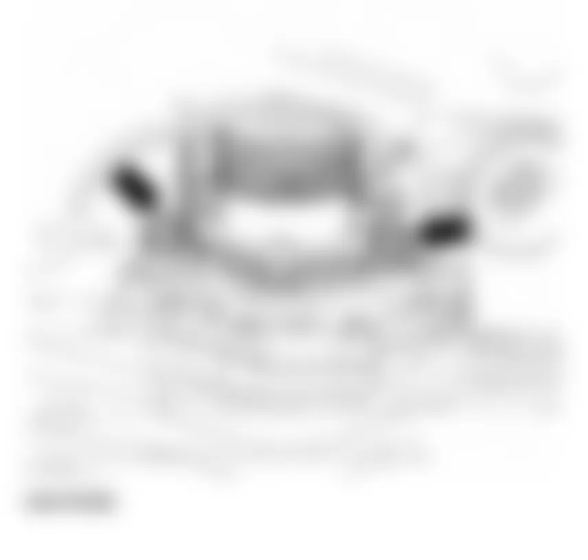
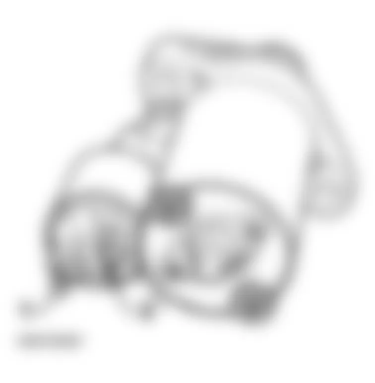
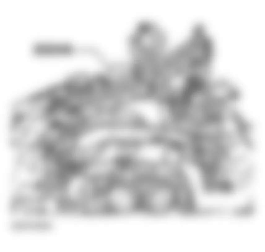
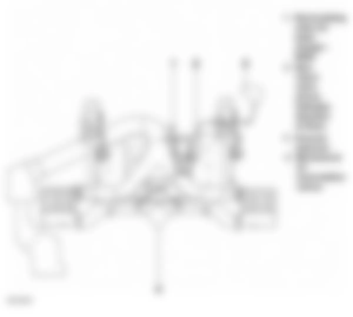
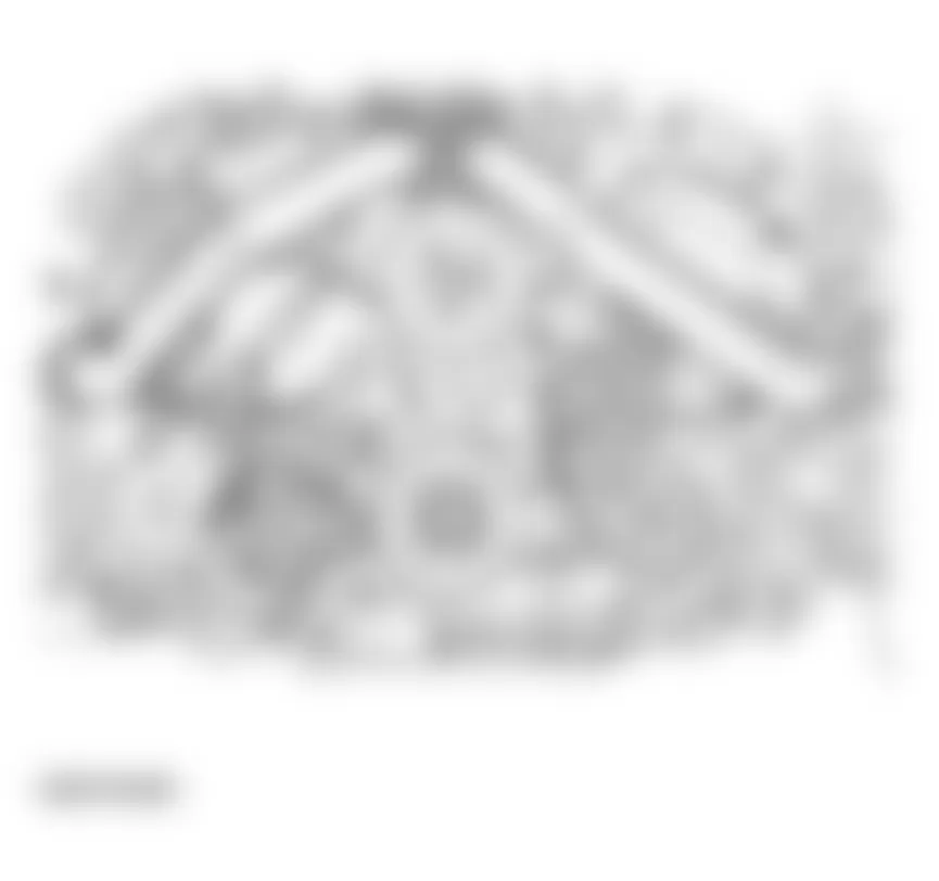
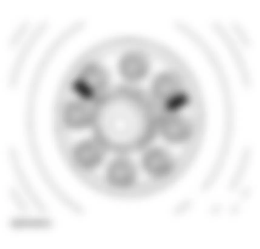
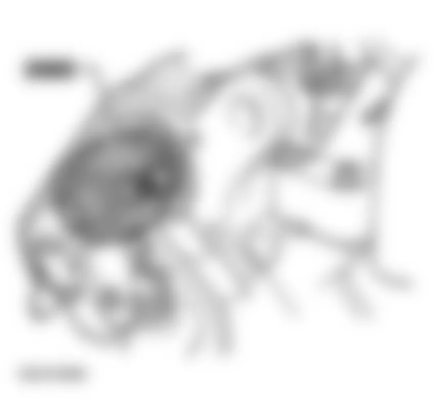
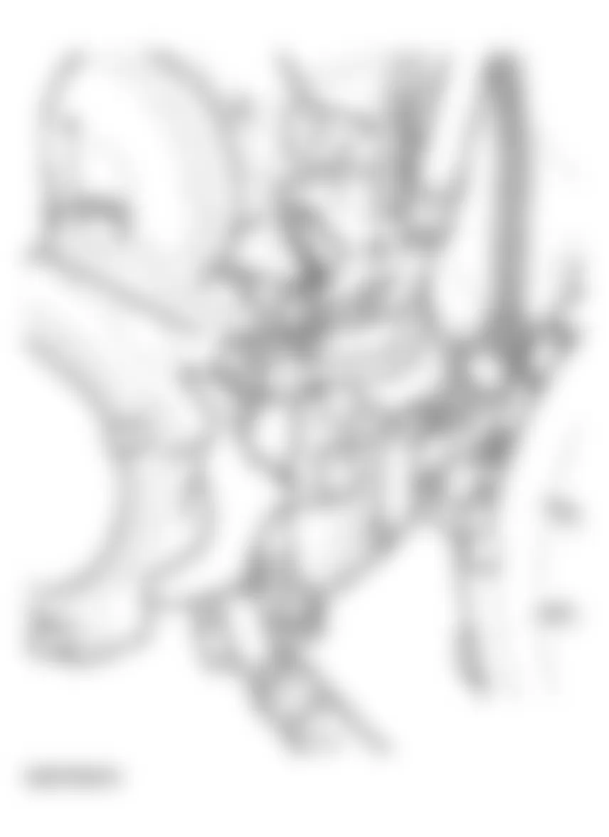
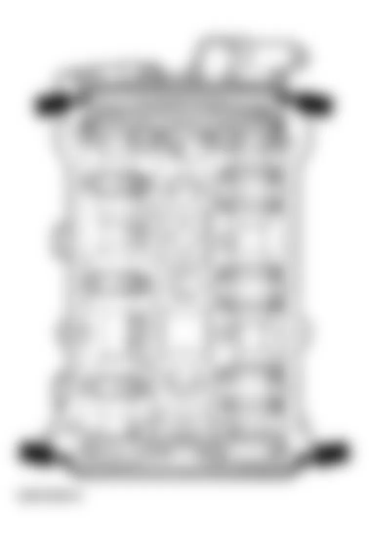
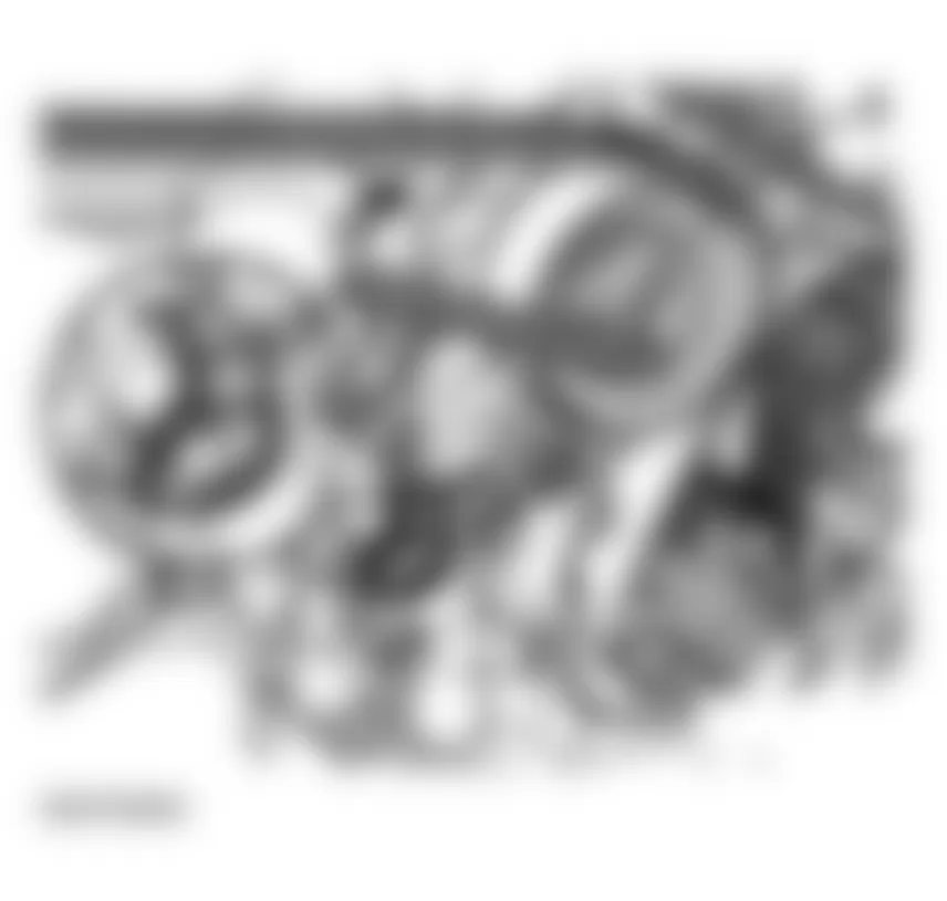
Fig. 7: Audi allroad Quattro 2005 - Component Locations - Removing Sound-Proofing Material - Remove viscous fan counter-hold using 3212 wrench.
NOTE: The viscous fan has a LEFT-HANDED thread.
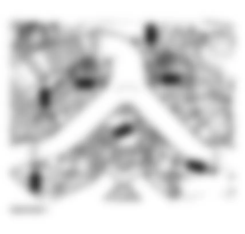
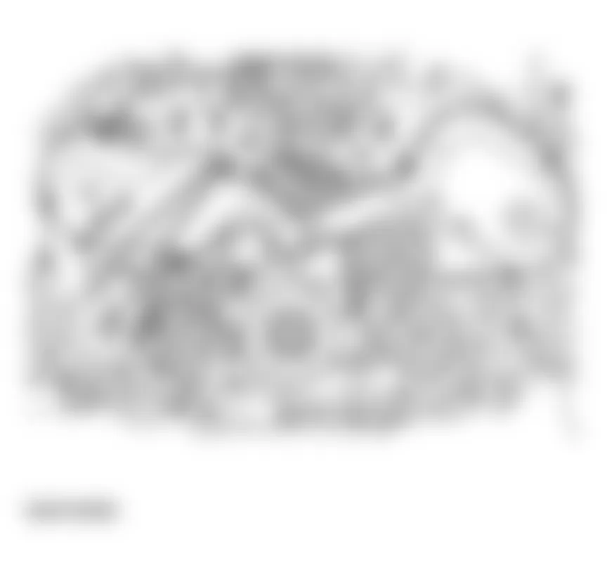
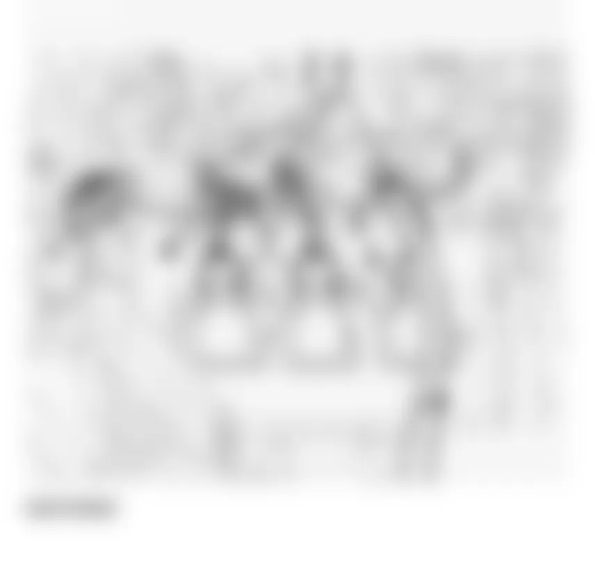
Fig. 8: Audi allroad Quattro 2005 - Component Locations - Removing Viscous Fan Using 3212 Wrench - Mark direction of rotation of ribbed belt
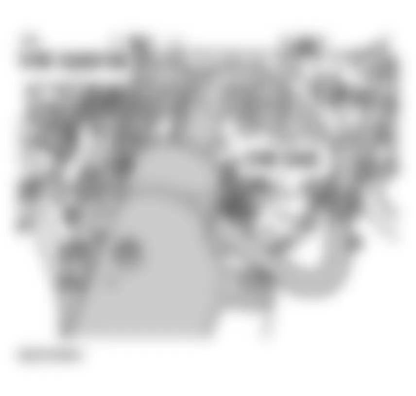
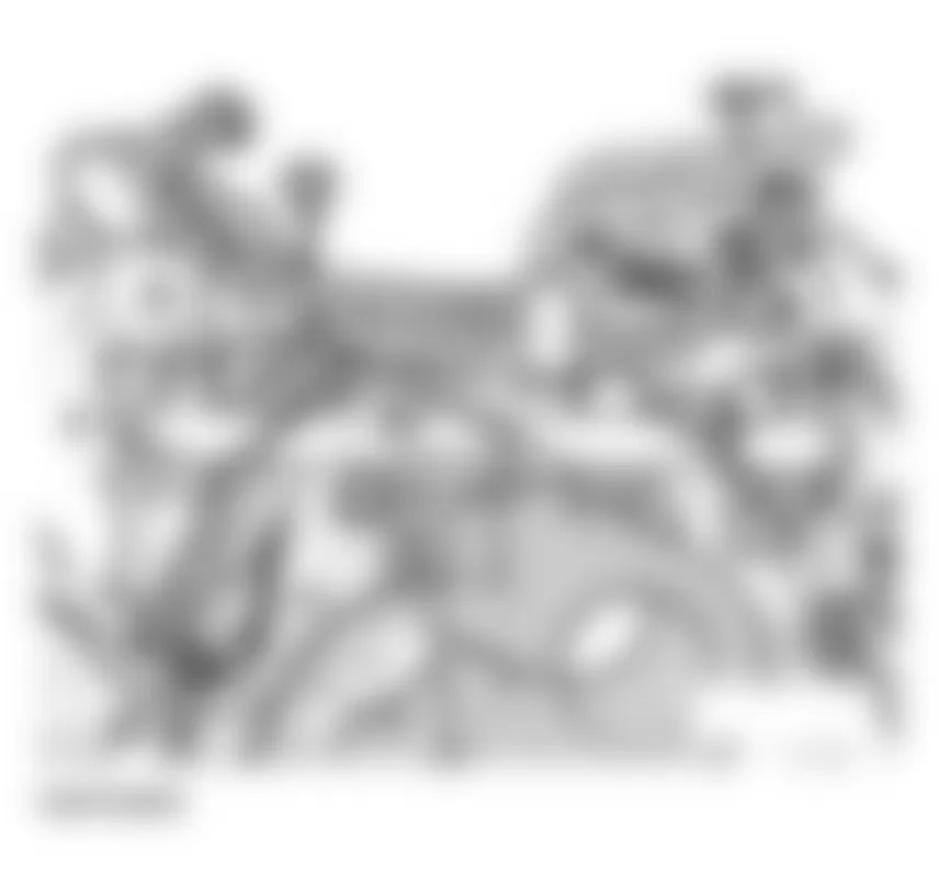
- To loosen ribbed belt, turn clockwise using 17 mm box wrench until two holes are aligned (arrow). Counter-hold in position using 3204 drift.
NOTE: Mark direction of rotation of ribbed belt. Reversing the direction in which it runs can ruin it. - Remove ribbed belt.
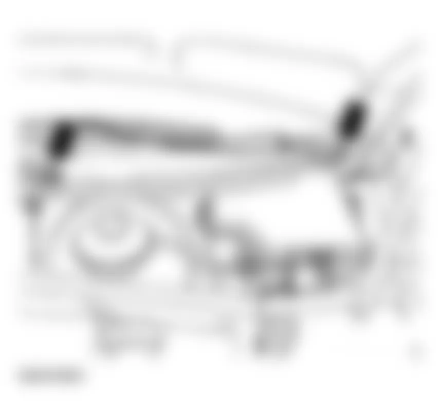
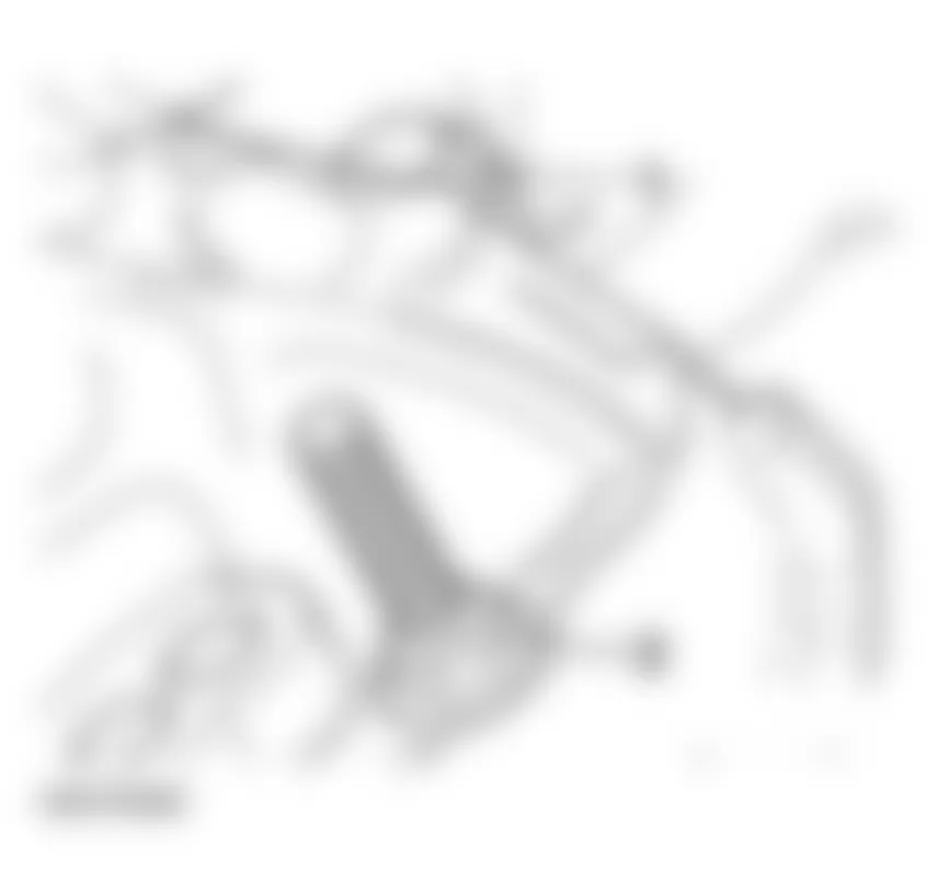
Fig. 9: Audi allroad Quattro 2005 - Component Locations - Turning Ribbed Belt Tensioner Clockwise - Cut coolant hoses -1- and -2-
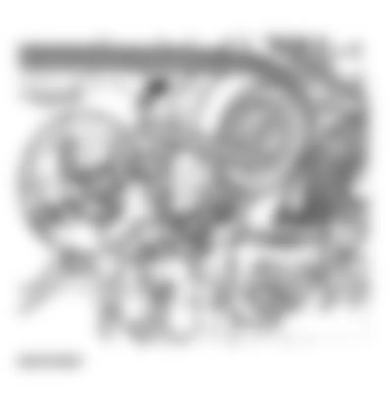
- Remove coolant reservoir (arrows).
- Disconnect connector for coolant level display.
- Remove valve cover (cylinder bank 4-6).
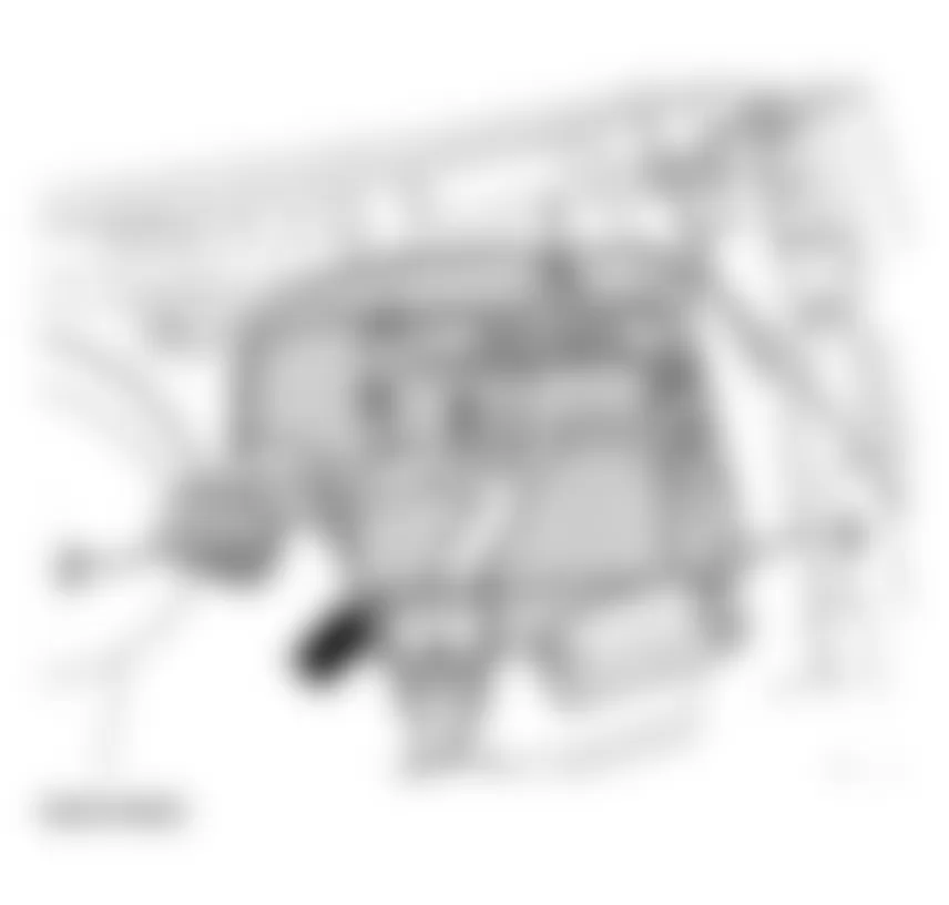
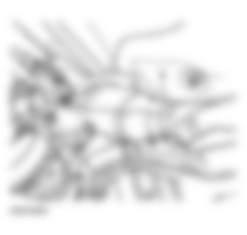
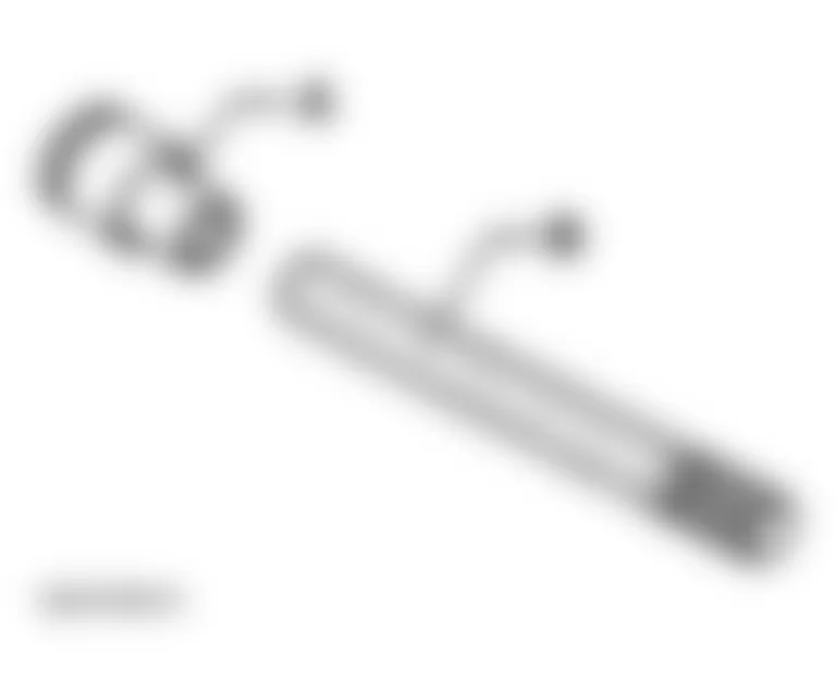
Fig. 10: Audi allroad Quattro 2005 - Component Locations - Removing Coolant Reservoir - Remove hose -1- to vacuum reservoir.
Fig. 11: Audi allroad Quattro 2005 - Component Locations - Removing Hose From Vacuum Reservoir - Remove air distributor (arrows).
Fig. 12: Audi allroad Quattro 2005 - Component Locations - Removing Air DistributorWARNING: Fuel system is under pressure! Before opening the system place a rag around the connection. Then release pressure by carefully loosening the connection. - Disconnect fuel supply and return lines -1- and -2- and move aside.
- Remove hose from Evaporative Emission (EVAP) canister purge regulator valve -3-.
- Disconnect connector -1- at Mass Air Flow (MAF) sensor. See Fig. 14
- Disconnect connectors -2- from power output stage and move cables aside.
- Remove air filter.
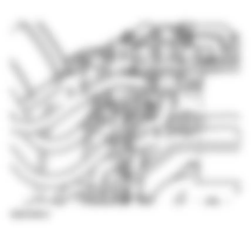
Fig. 14: Audi allroad Quattro 2005 - Component Locations - Removing Air Filter - Disconnect connector -1- for oxygen sensor at bulkhead. See Fig. 15.
- Disconnect connector -2- for knock sensor.
- Disconnect harness connector -3-.
- Move cables clear.
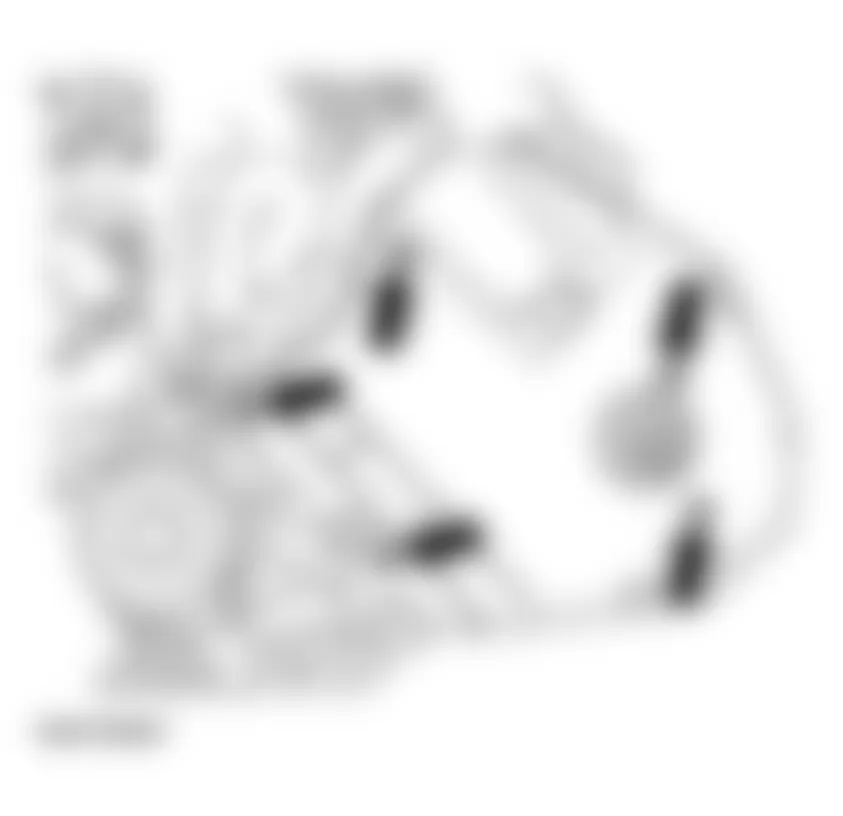
- Remove pressure hoses (arrows) from charge air cooler to left and right pressure lines.
See Caution before beginning repairs on the electrical system under ENGINE, REMOVING AND INSTALLING.
- Disconnect cable at B+ on battery.
- Disconnect B+ battery cable.
- Move cables to starter aside together with cable channels (arrows).
- Remove pressure lines -1-.
NOTE: Watch position of retaining strips -2-.
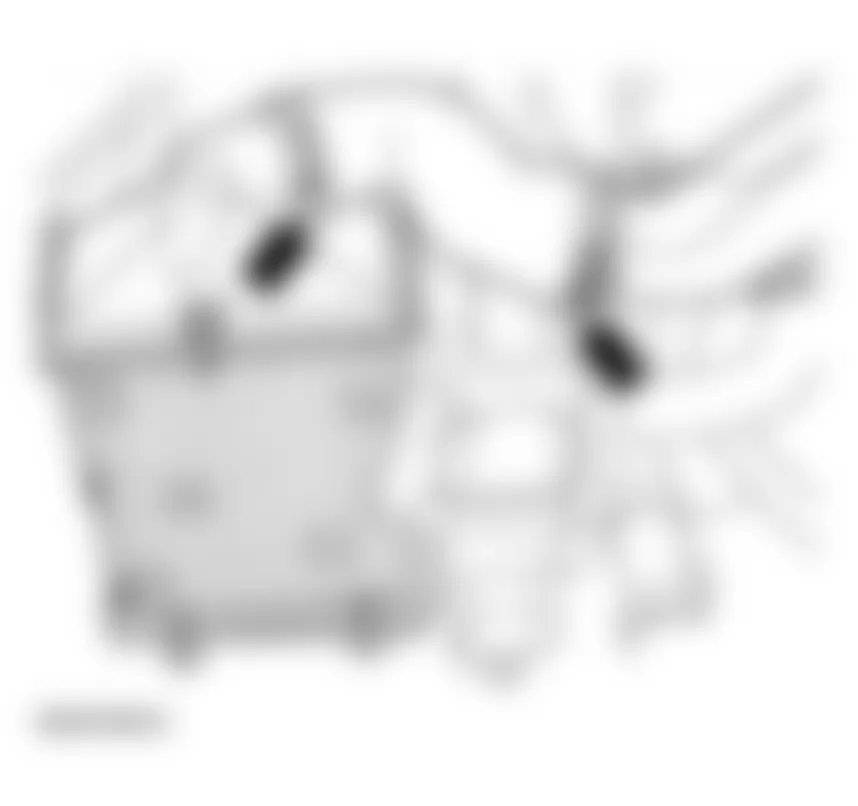
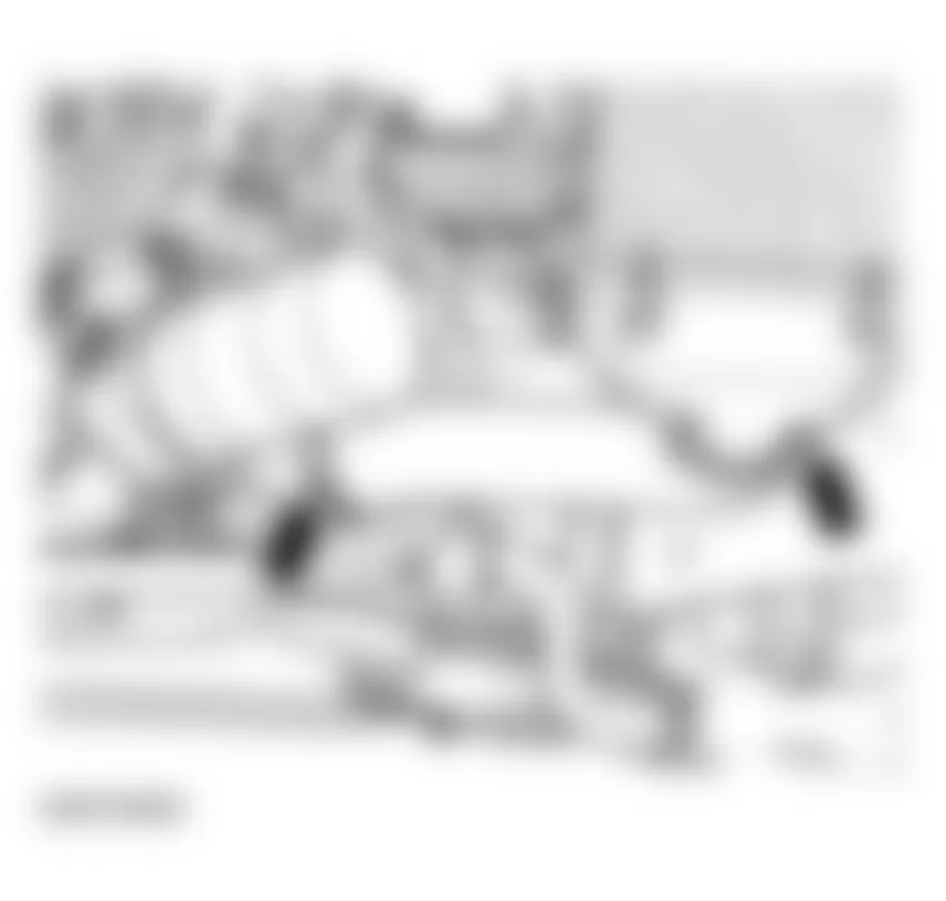
Fig. 18: Audi allroad Quattro 2005 - Component Locations - Removing Pressure Lines - Disconnect hose from power steering reservoir to power steering pump with special tool 3094. See Fig. 19.
- Disconnect power steering hose (arrow).
Fig. 19: Audi allroad Quattro 2005 - Component Locations - Disconnecting Power Steering Hose (Arrow) - Disconnect hydraulic line (arrow).
- Disconnect harness connector from vehicle speed sensor.
- Disconnect harness connector from reverse gear switch.
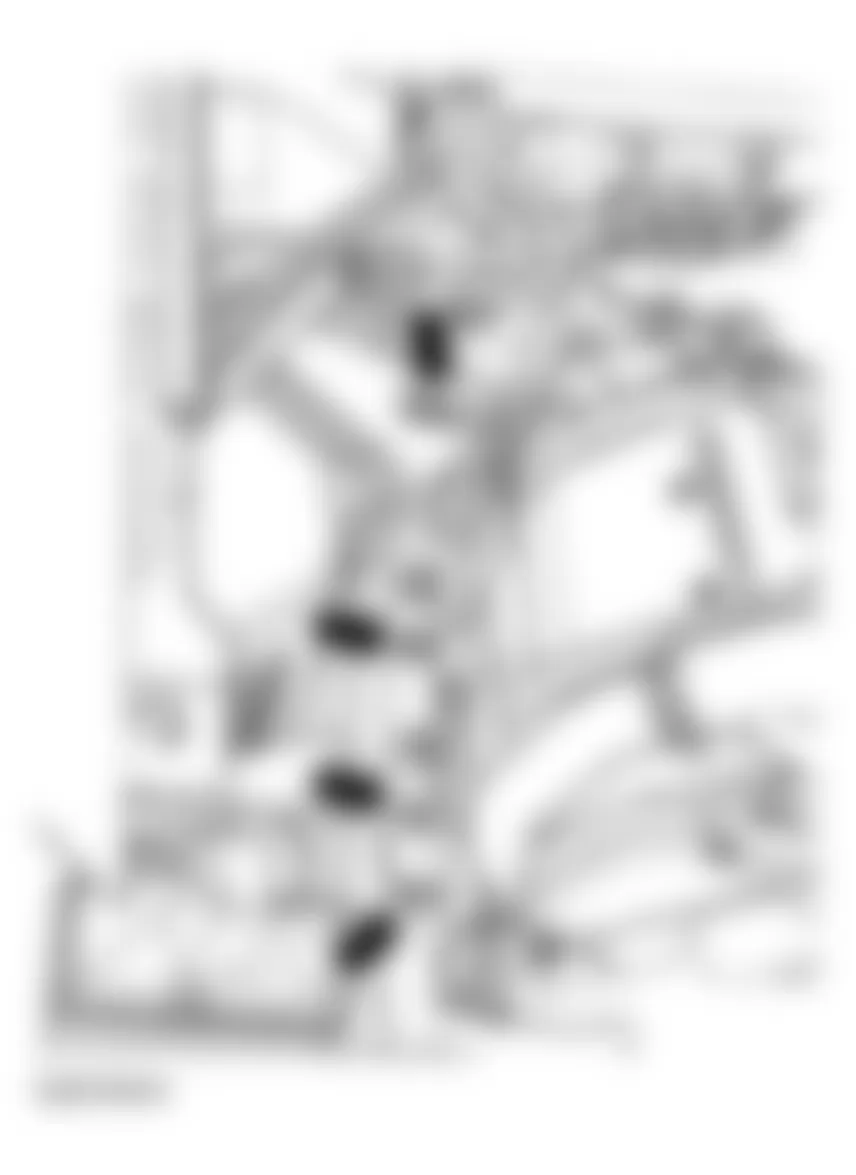
Fig. 20: Audi allroad Quattro 2005 - Component Locations - Disconnecting Hydraulic Line (Arrow) - Unscrew heat sensor -1- from right-hand turbocharger using 3035.
- Detach heat shield -2- from left and right turbochargers.
- Unscrew upper bolts -3- from front exhaust pipes at left and right turbochargers.
- Remove wiper arms (arrows).
- Disconnect retaining clip -1- at water deflector.
- Pull off left and right retaining clips -3- on water deflector.
- Remove water deflector.
- Remove cover -2- from E-box (electronics box).
- Open E-box in plenum.
Fig. 22: Audi allroad Quattro 2005 - Component Locations - Removing Wiper Arms - Unclip ECM retaining bracket.
- Remove ECM, disconnect harness connectors -2- and -3- and remove.
- Disconnect harness connectors -1-.
- Remove hose -1- to power brake booster at bulkhead.
- Disconnect ground (GND) -3-. See Fig. 24.
- Disconnect connectors -2- and -5- at bulkhead and remove lower part of connectors from bracket.
- Pull connector -4- out of bracket and move wiring clear.
- Remove bracket for cable plug.
- Remove both coolant hoses to heat exchanger at engine by un-clipping retaining clips on flange.
- Remove both coolant hoses to heat exchanger at engine by un-clipping retaining clips on flange.
- Release hose clamp -arrow-.
- Remove intake line -1-.
- Remove water line -2-.
- Remove pressure hoses -arrows- between turbocharger and charge air cooler (left and right sides).
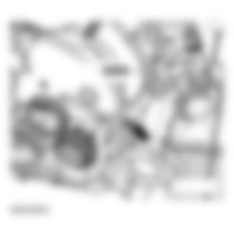
- Move aside cable -1- to starter by cutting cable tie and unclipping bracket (arrow).
- Remove hose -2- for cooling generator.
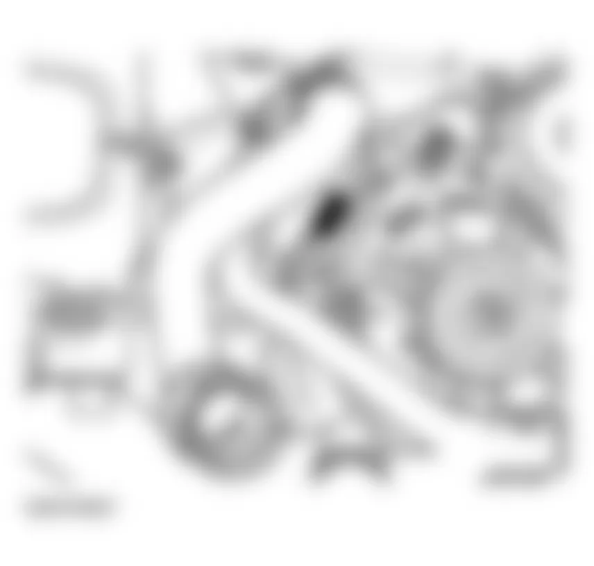
Fig. 27: Audi allroad Quattro 2005 - Component Locations - Removing Hose -2- For Cooling Generator - Disconnect ground (GND) (arrow) from engine support.
- Remove torque support -1-.
- Remove hose clamps (arrows).
- Remove coolant line -2-. See Fig. 29.
- Place VAG 1306 Drip Tray beneath engine.
- Remove oil filter.
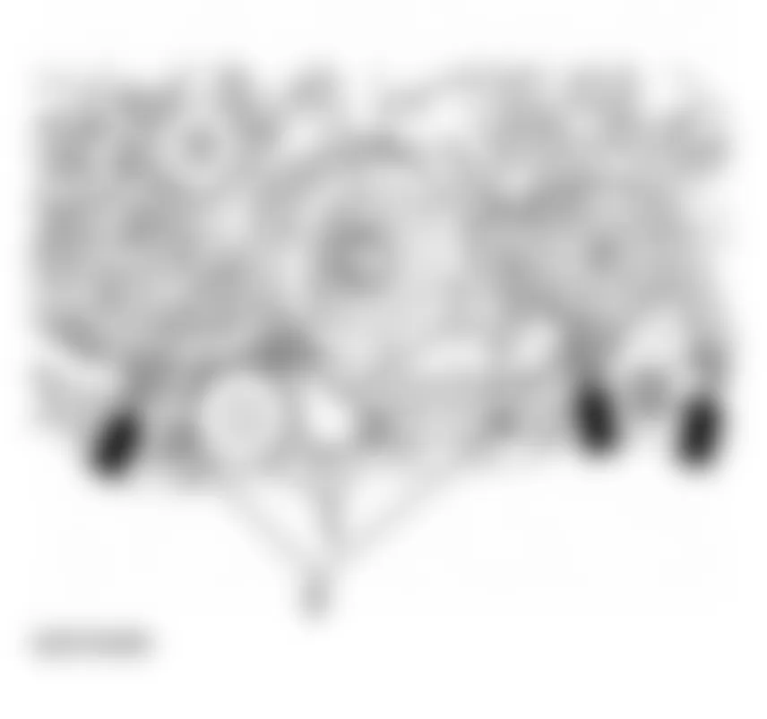
Fig. 29: Audi allroad Quattro 2005 - Component Locations - Removing Hose Clamps At Front Of Engine - Remove hose clamps (arrow).
- Remove oil cooler -1-.
Fig. 30: Audi allroad Quattro 2005 - Component Locations - Removing Oil Cooler - Remove heat shield (arrows) above left and right drive axle to transmission.
- Remove hose clamp -1- from left and right heat shield for turbocharger.
- Unbolt left and right exhaust pipes -2- from turbocharger.
- Detach air conditioner line from oil pan -arrow-.
CAUTION: Do not open the refrigerant circuit of the AC system. - Remove A/C compressor -1...2-.
- Attach A/C compressor (with refrigerant hoses attached) to vehicle using wire.
Fig. 34: Audi allroad Quattro 2005 - Component Locations - Removing A/C CompressorNOTE: - When installing pay attention to guide bushings.
- When installing first insert bolt -1- in A/C compressor.
- Do not bend or stretch lines or hoses as condenser and/or refrigerant lines/hoses may be damaged.
Vehicles with automatic transmission:
- Remove right charge air cooler by disconnecting upper hose connection; charge air cooler supported in 3x rubber bearings.
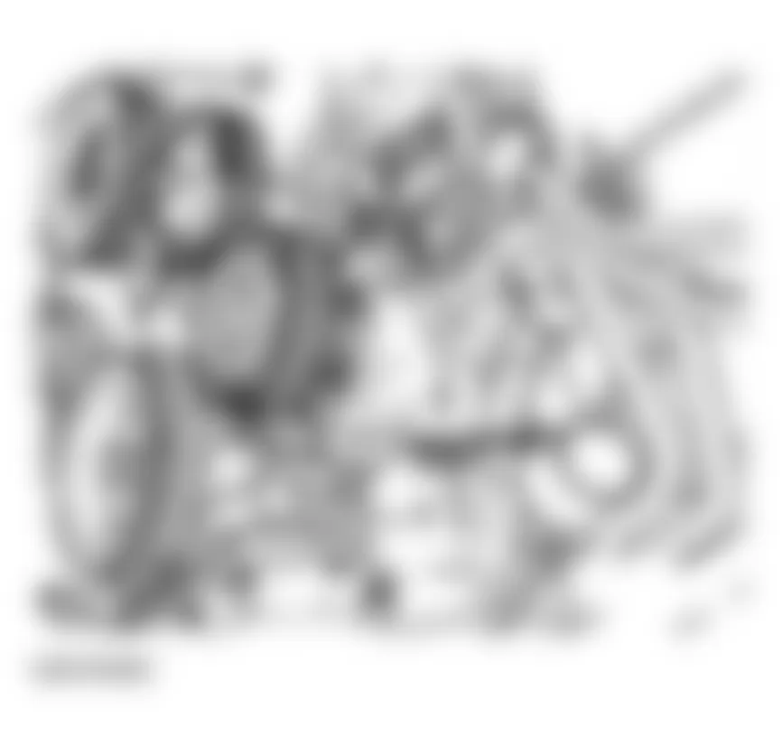
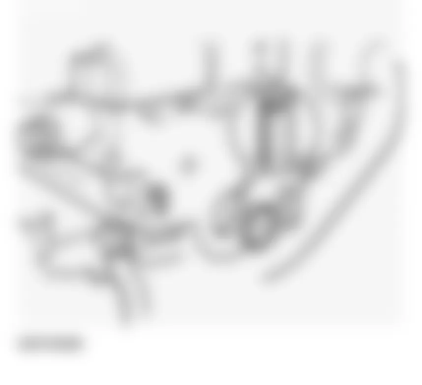
- Disconnect air guide at generator support -3-.
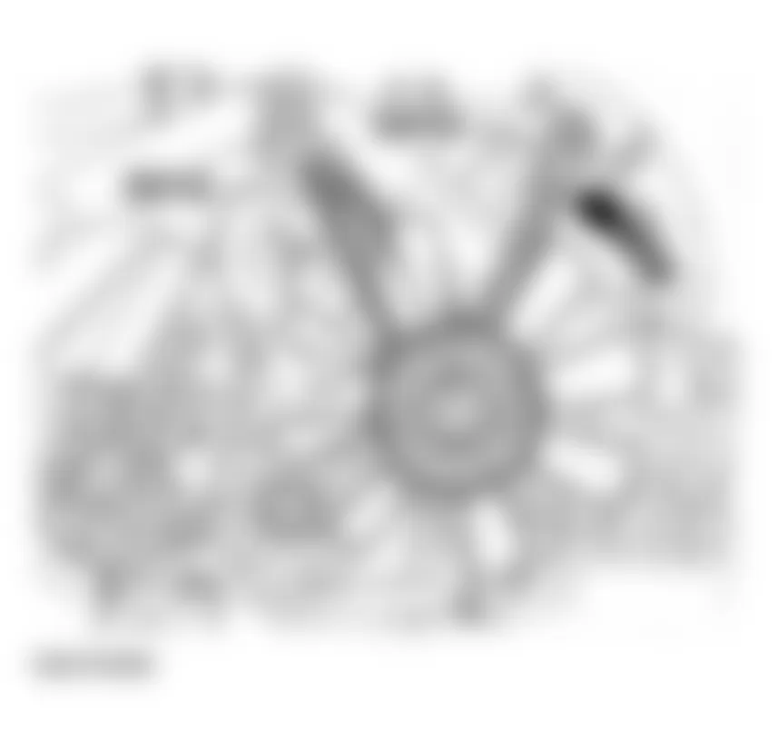
- Unbolt cable at terminal 30/B+ -1-. Tightening torque: 16 Nm
- Unbolt cable at terminal D+ -2-. Tightening torque: 4 Nm
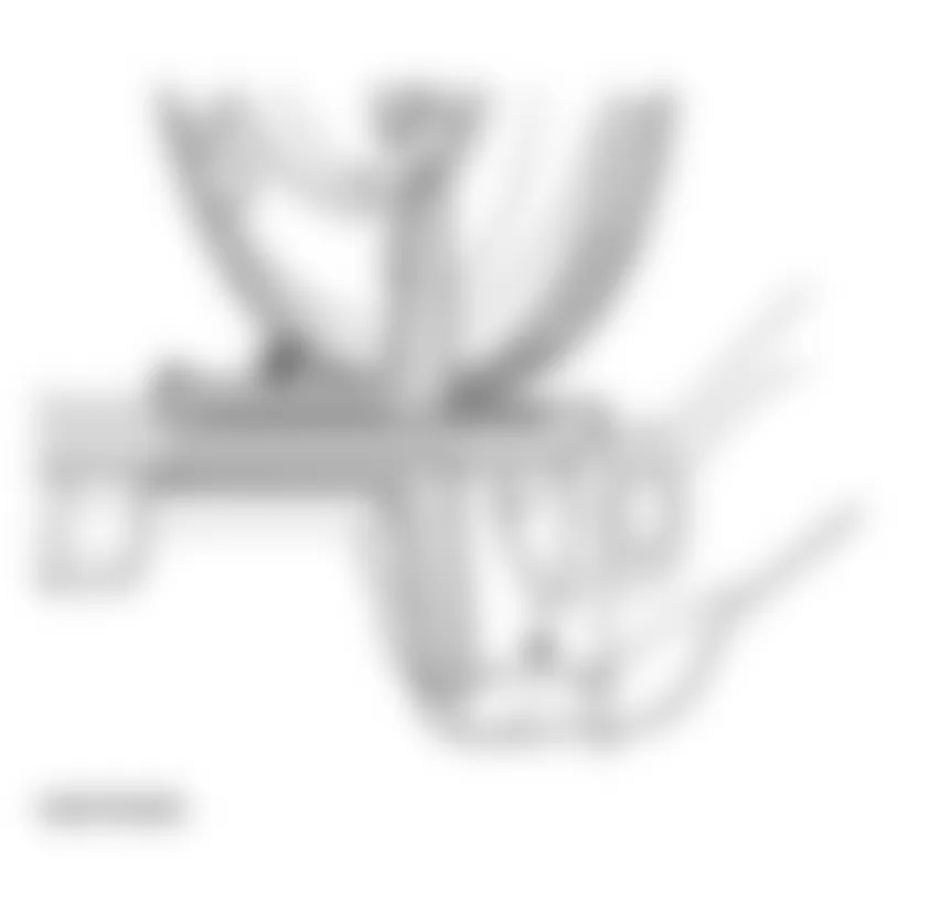
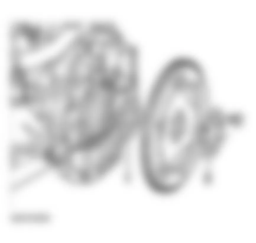
- Remove hex socket bolt -1-, retaining nut -2-. Tightening torque: 45 Nm. See Fig. 36.
- Remove bolt -3-. Tightening torque: 22 Nm
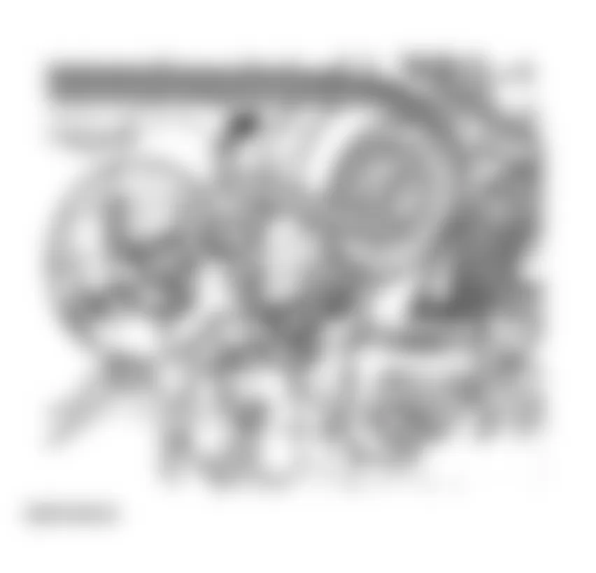
- Remove generator -4- downward and out.
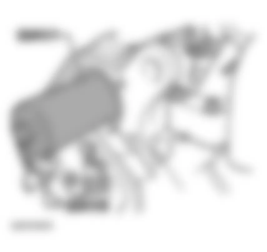
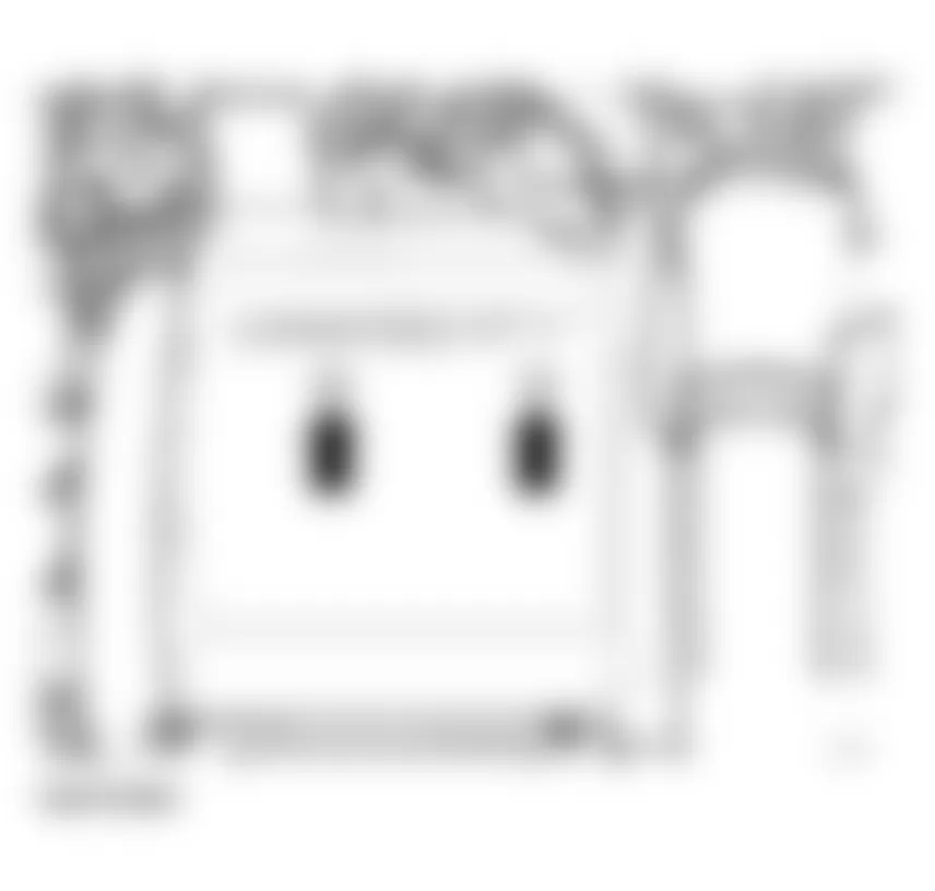
Fig. 36: Audi allroad Quattro 2005 - Component Locations - Removing Generator


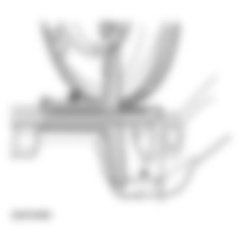
- - Remove air intake -1-.
- - Securing points for oil and A/C lines
- - Securing point to engine block
- - Remove hose clamp
Fig. 37: Audi allroad Quattro 2005 - Component Locations - Removing Air Intake
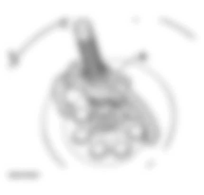
- Unbolt cable for terminal 30/B+ -1-. Tightening torque: 16 Nm
- Disconnect connector for terminal 50 -2-.
Fig. 38: Audi allroad Quattro 2005 - Component Locations - Unbolting Cable For Starter Terminals - Remove right wheel.
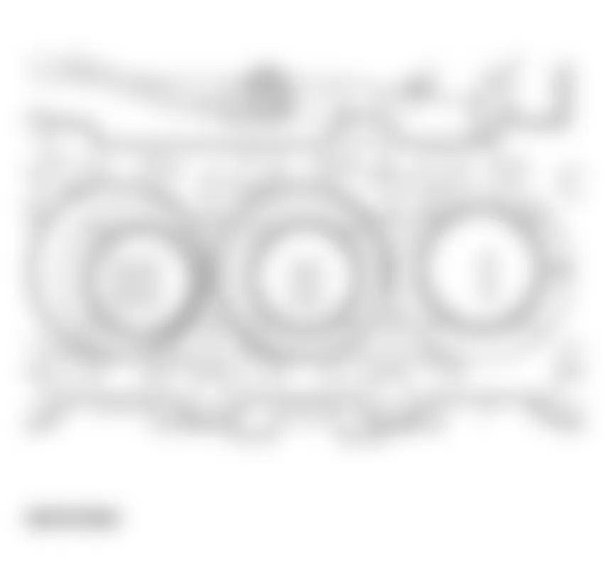
- Remove upper bolt -1- through right wheelhousing. Tightening torque: 65 Nm. See Fig. 39.
- Remove lower bolt from engine side. Tightening torque: 65 Nm
- Remove starter forward and out.
- Using special tool V175 disconnect torque converter from drive plate.

Audi allroad Quattro 2005 - All models
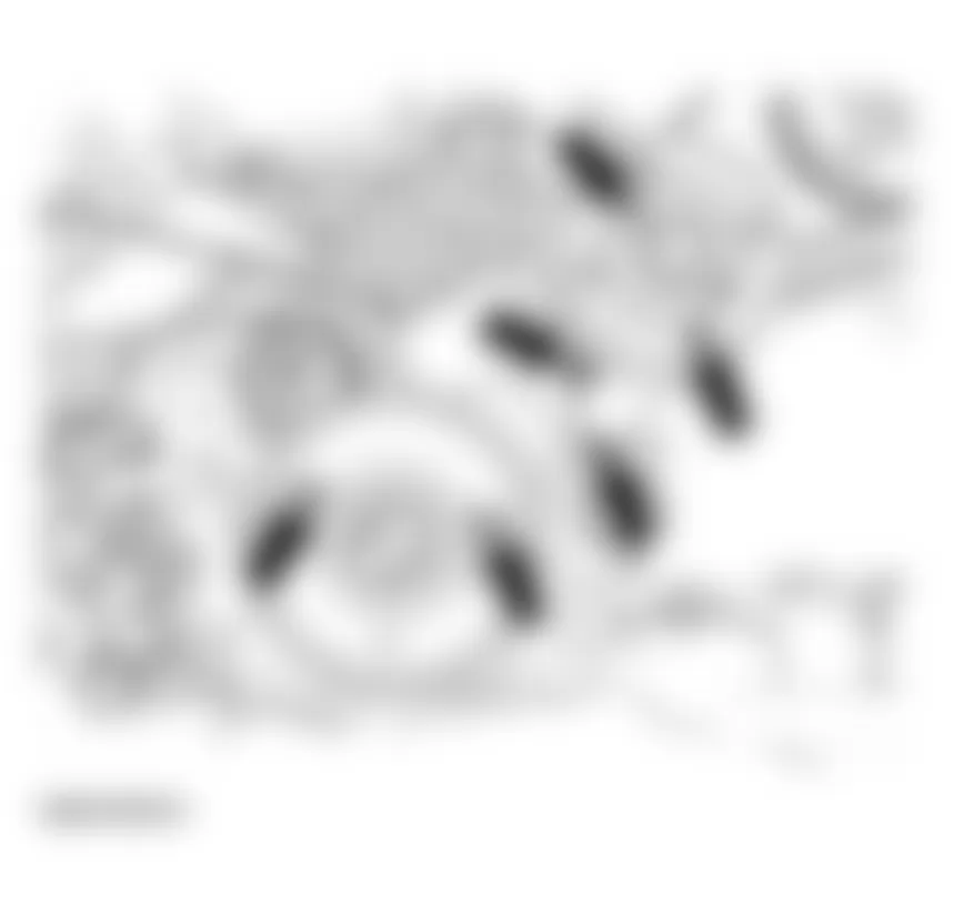
- Mark positions of securing points -1- and locating sleeves -2- under engine mountings on right and left sides.
- Remove nuts -1- at engine mountings on left and right sides.
NOTE: When installing, make sure that locating sleeves -2- engage in position. - Set up support bar 10-222 A on bolted flanges of wing panels using 10-222A1 and extension 10-222A3.
- Lift engine upward with support bar 10-222A.
- Remove engine/transmission bolts from underneath.
- Remove support bar.
- Remove engine/transmission bolts from above.
- Attach lifting tackle 2024 A at rear right and front left, and secure attachment points.
NOTE: To balance the center of gravity of the engine, secure the hook attachments in the positions shown in the illustration. WARNING: The hook attachments and locating pins on the lifting tackle must be secured with locking pins. - Remove front left wheel.
- Support transmission using floor jack.
- Push engine crane VAG1202A into position and attach to engine sling.
NOTE: Verify that all hoses and lines between engine and transmission have been disconnected. - Carefully pull engine out toward front until free.
- Guide engine forward out of engine compartment.
- Remove spacer between engine and transmission.
Audi allroad Quattro 2005 - Engine, attaching to engine stand
For engine disassembly and assembly, mount engine to an assembly stand using VW 540 Holding Fixture together with VW540/1B auxiliary pieces.
Fig. 44: Audi allroad Quattro 2005 - Component Locations - Identifying Engine Stud
Audi allroad Quattro 2005 - Engine, installing
Installation is reverse of removal, noting the following:
NOTE: Always replace self-locking nuts, bolts as well as gaskets and O-rings.
- Install clutch
All drive vehicles:
See CLUTCHES - 01E, AWD .
- Make sure centering sleeves for engine to transmission are correctly installed in cylinder block. Install or replace if necessary.
- Lubricate splines on transmission input shaft lightly using thin coating of G 000 100. Do not lubricate guide sleeve for release bearing.
- Check centering of clutch disc.
- For vehicles with manual transmission, a pilot needle bearing must be installed in crankshaft. Install if necessary. See NEEDLE BEARING IN DUAL-MASS FLYWHEEL, REMOVING AND INSTALLING.
- For vehicles with automatic transmission, install bushing in flywheel.
- Install spacer between engine and transmission.
- Install ribbed belt. See RIBBED BELT, REMOVING AND INSTALLING.
- Fill with coolant. See COOLING SYSTEM, DRAINING AND FILLING .
NOTE: - Only reuse drained coolant if cylinder head or engine block was not replaced.
- Dirty coolant cannot be reused.
- Install engine mounts without tension or preload by aligning engine with shaking motions before tightening engine mounts.
- Install lock carrier with attachments.
See LOCK CARRIER WITH ATTACHMENTS, REMOVING AND INSTALLING .
- Install bumper.
See FRONT BUMPER .
- Align exhaust system so it is free of stress. See EXHAUST SYSTEM, ALIGNING FREE OF STRESS .
- Attach vacuum lines. See VACUUM DIAGRAM - COMPLETE.
NOTE: Only remove and install spark plugs using 3122B spark plug removal tool. - For harness connectors and routing:
See System Wiring Diagrams .
See Caution for connecting Telematics battery under ENGINE, REMOVING AND INSTALLING.
- After connecting battery, enter anti-theft code for radio.
See Radio operating manual.
- Fully close front power windows to stop.
- Activate all power window switches ("up" for at least one second to activate automatic window raising/lowering).
- Set clock to correct time.
- Check engine oil level before starting engine.
Audi allroad Quattro 2005 - Tightening torques
NOTE:
Audi allroad Quattro 2005 - Manual transmission
Transmission to engine (6-cylinder)
Audi allroad Quattro 2005 MANUAL TRANSMISSION-TO-ENGINE TIGHTENING TORQUES
Item No. Bolt Number Nm 1 M 12 x 90 2 65 2 M 12 x 100 1 65 3 M 10 x 60 1 45 4 M 10 x 60 2 45 5 M 10 x 150 1 65 6 M12 x 130 1 65 7 M12 x 80 2 65
-A- Centering sleeves

Audi allroad Quattro 2005 - Automatic transmission
Engine/transmission mountings (6-cylinder engine)
Audi allroad Quattro 2005 AUTOMATIC TRANSMISSION-TO-ENGINE TIGHTENING TORQUES
Item No. Bolt Number Nm 1 M 12 x 90 2 65 2 M 12 x 100 1 65 3 M 10 x 70 1 45 4 M 10 x 60 2 45 5 M 10 x 100 1 65 6 M12 x 110 1 65 7 M12 x 80 2 65

-A- Dowel sleeves for centering
Audi allroad Quattro 2005 TIGHTENING TORQUES: ENGINE INSTALLATION
Threaded assemblies Tightening torque Nuts and bolts M6 10 Nm Nuts and bolts M8 20 Nm Nuts and bolts M10 45 Nm Nuts and bolts M12 60 Nm Except for the following: Head line to turbocharger 25 Nm Heat shield to turbocharger 10 Nm Clamp for exhaust pipe 40 Nm Engine support to engine mount M10 45 Nm A/C Compressor to bracket 25 Nm Torque support 45 Nm Heat shields above drive axles to transmission 25 Nm Torque converter 85 Nm
For fan, see VISCOUS FAN, REMOVING AND INSTALLING.
Audi allroad Quattro 2005 - VACUUM HOSE DIAGRAM(S)
NOTE: For vacuum diagram (partial systems), see VACUUM LAYOUT - PARTIAL SYSTEMS.
Audi allroad Quattro 2005 - Vehicles without Secondary Air Injection (AIR)
NOTE: The following list refers to items in Fig. 47.
- - To reservoir under right front wheel housing shell.
- - Air cleaner
- - Mass Air Flow (MAF) sensor
- - Evaporative Emission (EVAP) canister
- - Turbocharger engine bank 1
- - Check valve (arrow indicates direction of flow through valve)
- - Wastegate bypass regulator valve -N75
- - Evaporative Emission (EVAP) canister purge regulator valve -N80-
- Crankcase check valve
- - Collector housing for crankcase ventilation
- - To power brake booster
- - Check valve (arrow indicates direction of flow through valve)
- - Vacuum limiter valve
- - Fuel pressure regulator
- - Check valve (arrow indicates direction of flow through valve)
- - To Leak Detection Pump (LDP) -V144-
- - Vacuum reservoir
- - Turbocharger engine bank 2
- - Pressure unit for charge air pressure regulation
- - Charge air cooler engine bank 2
- - Pressure hose engine bank 2
- - Pressure line engine bank 2
- - Cut-out valve (mechanical circulation valve)
- - Pressure hose
- - Recirculating valve for turbocharger - N249-
- - Connection hose
- For both charge air coolers
- - Connection hose
- - Cut-out valve (mechanical circulation valve)
- - Check valve for crankcase ventilation
- - Pressure line engine bank 1
- - Pressure hose engine bank 1
- - Charge air pressure cooler engine bank 1
- - Pressure unit for charge air pressure regulation

Audi allroad Quattro 2005 - Vehicles with Secondary Air Injection (AIR)
NOTE: The following list refers to items in Fig. 48.
- - To reservoir under right front wheel housing shell.
- - Air cleaner
- - Mass Air Flow (MAF) sensor
- - Evaporative Emission (EVAP) canister
- - Turbocharger engine bank 1
- - Combination valve for secondary air injection (AIR)
- - Secondary Air Injection (AIR) solenoid valve - N112-
- - Wastegate bypass regulator valve -N75
- - Check valve for crankcase ventilation
- - Collector housing for crankcase ventilation
- - To power brake booster
- - Check valve (arrow indicates direction of flow through valve)
- - Secondary Air Injection (AIR) pump motor -V101-
- - Vacuum limiter valve
- - Fuel pressure regulator
- - To Leak Detection Pump (LDP) -V144-
- - Vacuum reservoir
- - Turbocharger engine bank 2
- - Pressure unit for charge air pressure regulation
- - Combination valve for secondary air injection (AIR)
- - Check valve (arrow indicates direction of flow through valve)
- - Charge air pressure cooler engine bank 2
- - Pressure hose engine bank 2
- - Recirculating valve for turbocharger -N249-
- - Cut-out valve (mechanical circulation valve)
- - Connection hose
- - Pressure line engine bank 2
- - Connection hose
- for both charge air coolers
- - Check valve for crankcase ventilation
- - Connection hose
- - Cut-out valve (mechanical circulation valve)
- - Pressure line engine bank 1
- - Pressure hose engine bank 1
- - Check valve (arrow indicates direction of flow through valve)
- - Evaporative Emission (EVAP) canister purge regulator valve -N80-
- - Charge air pressure cooler engine bank 1
- - Pressure unit for charge air pressure regulation

Audi allroad Quattro 2005 - Vacuum layout - partial systems Air flow diagram (general)
NOTE: The following list refers to items in Fig. 49.
- - Air filter
- - Mass Air Flow (MAF) Sensor-G70-
- - Intake side of turbocharger, Bank 1
- - Turbocharger, Bank 1
- - Pressure side of turbocharger, Bank 1
- - Air duct
- - Intake side of turbocharger, Bank 2
- - Turbocharger, Bank 2
- - Pressure side of turbocharger, Bank 2
- - Charge air cooler, Bank 2
- - Intake manifold
- - Throttle valve control module -J338-
- - Charge air pressure cooler, Bank 1
Fig. 49: Audi allroad Quattro 2005 - Component Locations - Air flow Vacuum Diagram (General)
Audi allroad Quattro 2005 - Charge air pressure control system
NOTE: The following list refers to items in Fig. 50.
- - Turbocharger, Bank 1
- - Wastegate Bypass Regulator Valve -N75-
- - Distributor piece
- - Turbocharger, Bank 2
Audi allroad Quattro 2005 - Fuel tank breather system (EVAP system)
NOTE: The following list refers to items in Fig. 51.
- - Activated charcoal filter
- - Solenoid valve 1 for activated charcoal filter - N80-
- - Non-return valves (arrows indicate direction of flow)
Audi allroad Quattro 2005 - Air diversion system (air "recirculation" on overrun)
NOTE: The following list refers to items in Fig. 52.
- - Recirculating valve for turbo charger -N249-
- - Non-return valve (arrow indicates direction of flow)
- - Vacuum reservoir
- - Mechanical air recirculation valves
Audi allroad Quattro 2005 - Crankcase breather system
NOTE: Depending on whether the vehicle has a manual transmission or an automatic transmission, the hose layout around the distributor piece (Item 2) will be different. This is because vehicles with automatic transmission also have a suction jet pump. See SUCTION JET PUMP (VEHICLES WITH AUTOMATIC TRANSMISSION).
NOTE: The following list refers to items in Fig. 53.
- - Connection on valve cover for cylinder bank 1
- - Distributor piece
- - Connection on crankcase
- - Pressure-limiting valve
- - Connection on valve cover for cylinder bank 2
- - Fuel pressure regulator
- - Non-return valve (arrow indicates direction of flow)
- - Non-return valve (arrow indicates direction of flow) . See also FUEL TANK BREATHER SYSTEM (EVAP SYSTEM).

Audi allroad Quattro 2005 - Suction jet pump (vehicles with automatic transmission)
NOTE: The following list refers to items in Fig. 54.
- - To air cleaner
- - Non-return valve (arrow indicates direction of flow)
- - Distributor piece (simplified)
- - To brake servo
- - Suction jet pump
- - Air duct
- - Connection for crankcase breather
- - To intake side of turbocharger, Bank 2
- - Intake manifold
- - To intake side of turbocharger, Bank 1
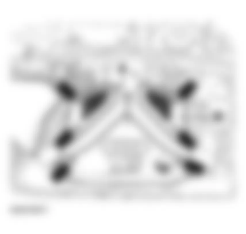
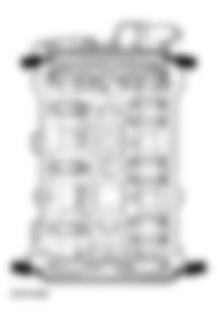
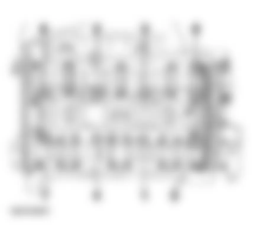
Audi allroad Quattro 2005 - Installation position, overview
NOTE: The following list refers to items in Fig. 55.
- - Harness connector for engine bank 1 Oxygen Sensor (O2S) behind Three Way Catalytic Converter (TWC) -G130- and heater for oxygen sensor 1 -Z29-
- 4-pin/green
- - Harness connector for engine bank 2 Oxygen Sensor (O2S) 2 behind Three Way Catalytic Converter (TWC) -G131- and heater for oxygen sensor 2 -Z30-
- 4pin/brown
- - Harness connector for engine bank 1 Oxygen Sensor (O2S) behind Three Way Catalytic Converter (TWC) -G39- and Oxygen Sensor (O2S) heater -Z19-
- 4-pin/black
- - 3-way connector
- For Knock Sensor (KS) 1 -G61-
- - Engine Coolant Temperature (ECT) sensor -G62-
- At coolant line behind cylinder head engine bank 1
- - Wastegate bypass regulator valve -N75-
- - Evaporative Emission (EVAP) canister purge regulator valve -N80-
- - Sensor -1- for exhaust temperature -G235-
- At the left rear of the intake manifold; for vehicles with automatic transmission sensor -2-, exhaust temperature -G236- is also installed at this position.
- - Secondary Air Injection (AIR) solenoid valve -N112-
- Only for vehicles with automatic transmission
- - Secondary Air Injection (AIR) pump motor -V101-
- Only for vehicles with automatic transmission
- - Sensor -1- for exhaust temperature -G236-
- For vehicles with automatic transmission, this sensor is located at position -8- along with sensor -1- for exhaust temperature -G235-. The two sensors are installed in series.
- - Recirculating valve for turbocharger -N249-
- - Fuel pressure regulator
- - Camshaft Position (CMP) sensor -G40-
- Engine bank 2
- - Secondary Air Injection (AIR) pump relay -J299-
- Only for vehicles with automatic transmission
- - Motronic Engine Control Module (ECM) -J220-
- - 3-way connector
- For Engine Speed (RPM) sensor -G28-
- Gray
- - 3-way connector
- For Knock Sensor (KS) 2 -G66-
- - Harness connector for Heated Oxygen Sensor (HO2S) 2 -G108- and Oxygen Sensor (O2S) 2 heater -Z28-
- 4-pin/black
- - Valve -2- for camshaft adjustment -N208-
- - Throttle Valve Control Module -J338-
- With throttle drive (power accelerator actuation) -G186-, angle sensor -1- for throttle drive (power accelerator actuation) -G187-, and angle sensor -2- for throttle drive (power accelerator actuation) -G188-
- - Charge air pressure sensor -G31-
- Located in rubber shroud in front of throttle valve control module
- - Camshaft Position (CMP) sensor 2 -G163-
- Engine bank 1
- - Power output stage 2 -N192-
- For ignition coils engine bank 2
- - Power output stage -N122-
- For ignition coils engine bank 1
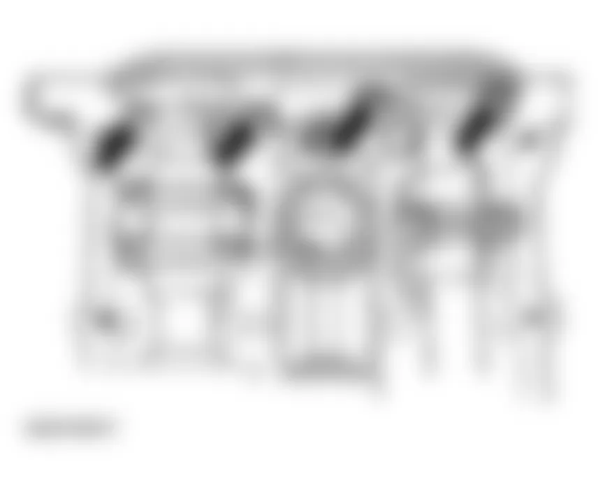
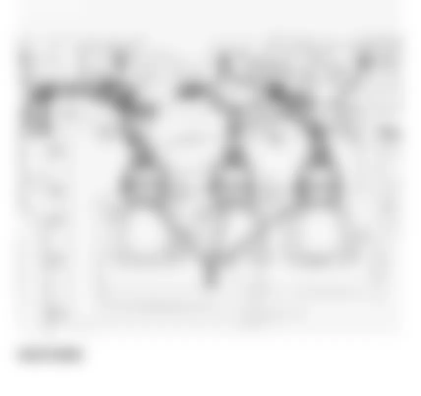
NOTE: The following list refers to items in Fig. 56. - - Valve -1- for camshaft adjustment -N205-
- - Engine bank 1, Heated Oxygen Sensor (HO2S) -G39- -Z19-
- - Knock Sensor (KS) 1 - G61-
- - Knock Sensor (KS) 2 - G66-
- - Engine Speed (RPM) sensor -G28-
- Located in transmission housing above sensor disk
- - Engine bank 2, Heated Oxygen Sensor (HO2S) 2 -G108- -Z28-
- - Ignition coils engine bank 2
- Ignition coil 4 -N163-
- Ignition coil 5 -N164-
- Ignition coil 6 -N189-
- - Fuel injectors
Cylinder bank 2
- Cylinder 4 fuel injector -N33-
- Cylinder 5 fuel injector -N83-
- Cylinder 6 fuel injector -N84-
- - Intake Air Temperature (IAT) sensor -G42-
- On the lower front part of the intake manifold, near the throttle valve control module
- - 2-way connector
- For Intake Air Temperature (IAT) sensor (measurements are made at this connector)
- - Fuel Injectors
Cylinder bank 1
- Cylinder 1 fuel injector -N30-
- Cylinder 2 fuel injector -N31-
- Cylinder 3 fuel injector -N32-
- - Ignition coils engine bank 1
- Ignition coil 1 -N-
- Ignition coil 2 -N128-
- Ignition coil 3 -N158-
- - Mass Air Flow (MAF) sensor -G70-


Audi allroad Quattro 2005 - Engine - Crankshaft, Cylinder block Engine crankshaft/crankcase, disassembly and assembly Ribbed belt, removing and installing Removing
- Remove noise insulation -arrows-.
- Remove bumper.
See FRONT BUMPER .
- Move lock carrier to service position.
See LOCK CARRIER, SERVICE POSITION .
Fig. 57: Audi allroad Quattro 2005 - Component Locations - Removing Noise Insulation - Remove viscous fan (counter-hold with pin wrench 3212).

NOTE: Viscous fan has LEFT-HAND thread: turn in direction indicated.
Fig. 58: Audi allroad Quattro 2005 - Component Locations - Removing Viscous Fan With Pin Wrench 3212

- Mark direction of rotation of ribbed belt.
- Loosen ribbed belt by turning to right using a 17 mm box wrench until two holes are aligned with each other -arrow- and hold in position with mandrel 3204.
NOTE: Mark the direction of rotation of the ribbed belt with chalk or felt pen before removing. A used belt can break if it rotates in the opposite direction when reinstalled.
- Remove ribbed belt.
Audi allroad Quattro 2005 - Installing
- D1 - vehicles without air conditioner
- D2 - vehicles with air conditioner.

- Install ribbed belt onto crankshaft pulley and idler wheel first, and push belt onto tensioning roller last.
- Take out mandrel 3204.
NOTE: Viscous fan has LEFT-HAND thread: turn against direction indicated.
- Counter-hold belt pulley for viscous fan using wrench 3212 and tighten viscous fan using open-end wrench 3312 and torque wrench 1331 (left hand thread).
- Install lock carrier.
See LOCK CARRIER WITH ATTACHMENTS, REMOVING AND INSTALLING .
- Install bumper.
See FRONT BUMPER .
- Install noise insulation.
Tightening torque of viscous fan, see VISCOUS FAN, REMOVING AND INSTALLING
Audi allroad Quattro 2005 - Toothed belt, removing and installing Removing
- Remove ribbed belt. See RIBBED BELT, REMOVING AND INSTALLING.
- Remove bolts -arrows- and remove engine cover panel -C-.
Fig. 62: Audi allroad Quattro 2005 - Component Locations - Removing Bolts And Engine Cover Panel - Remove pressure hoses -arrows- between charge air coolers and pressure lines (left and right sides).
- Remove pressure lines -1-.
NOTE: Watch position of retaining strips -2-.
Fig. 64: Audi allroad Quattro 2005 - Component Locations - Removing Pressure Lines - Remove tensioner -1- for ribbed belt. See Fig. 65.
- Remove left and right toothed belt guards -2-.
- Remove center toothed belt guard -3-.
Fig. 65: Audi allroad Quattro 2005 - Component Locations - Removing Tensioner For Ribbed Belt - Turn crankshaft to TDC by hand. Marks -A- and -B- must be aligned. See Fig. 66.
NOTE: Turn over the engine at the central bolt on the crankshaft.
Fig. 66: Audi allroad Quattro 2005 - Component Locations - Turning Crankshaft To TDC By Hand - Check position of camshafts: larger holes in securing plates on camshaft sprockets must align opposite one another on the inside. If not, turn crankshaft one revolution further.
- Remove sealing plug from cylinder block, left.

TDC drilling in the crankshaft must be visible (or able to be felt) in line with the sealing plug hole.
CAUTION: Injury risk - do not turn engine while feeling for TDC drilling.
- Screw clamping bolt 3242 for crankshaft into sealing plug hole and tighten.
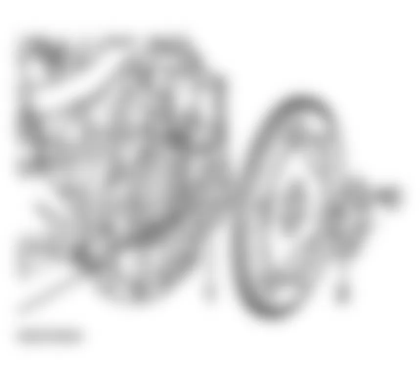
- Remove vibration damper on crankshaft.
NOTE: The central bolt does not have to be loosened to remove the vibration damper.
Fig. 68: Audi allroad Quattro 2005 - Component Locations - Removing Vibration Damper On Crankshaft - Remove idler wheel for ribbed belt -arrows-.
- Remove toothed belt guard behind vibration damper -arrows-.
NOTE: - Mark the direction of rotation of the toothed belt with chalk or felt pen before removing. A used belt can break if it rotates in the wrong direction when reinstalled.
- The toothed belt tensioning element is oil-damped and can therefore only be compressed slowly by applying constant pressure.
- Using a hex key, turn toothed belt tensioning roller -1- clockwise 8 mm in direction of arrow until tensioning lever -2- compresses tensioning element -3- sufficiently to enable special tool T400 11 to be fitted in drilling and in plunger.
- Insert special tool T 400 11, release toothed belt tensioning roller.
- Remove toothed belt.


Audi allroad Quattro 2005 - Installing
- Insert camshaft clamp 3391 in securing plates of two camshafts.
- Loosen both camshaft bolts and remove approx. 5 turns.
- Take out camshaft clamp 3391.
- Pull off both camshaft sprockets with special tool T40001.
- Reinstall both camshaft sprockets with securing plates and tighten hand-tight again.
NOTE: The camshaft sprockets should be just tight enough on the camshaft tapers so that they can still be turned but do not move axially. - Install toothed belt on all sprockets as illustrated.
- Install camshaft clamp 3391.
- Using a hex key, turn toothed belt tensioning roller -1- clockwise 8 mm in direction of arrow until special tool T 400 11 can be removed.
- Pre-tension toothed belt by turning in direction of arrow with a torque of 15 Nm using a torque wrench.
- Tighten bolts on camshaft sprockets.
- Install idler wheel for ribbed belt -arrows-.
- Install toothed belt guard behind vibration damper -arrows-.
- Install vibration damper. Note positions of locating lugs -arrows- on belt sprocket.
Fig. 76: Audi allroad Quattro 2005 - Component Locations - Installing Vibration Damper - Install toothed belt guard.
- Install ribbed belt. See INSTALLING.


Audi allroad Quattro 2005 TIGHTENING TORQUES: TOOTHED BELT
Component Torque Toothed belt sprocket to camshaft 55 Nm Idler wheel 45 Nm Toothed belt tensioning roller 20 Nm Pulley to crankshaft 20 Nm Toothed belt tensioning element 10 Nm Central bolt to crankshaft(1) 200 Nm + 180 Degree Turn(2)
(1) The central bolt must always be replaced.
(2) Turning in two stages of 90? is also permissible.
Audi allroad Quattro 2005 - Vibration damper, removing and installing
- Remove ribbed belt. See RIBBED BELT, REMOVING AND INSTALLING.
NOTE: The central bolt does not have to be loosened to remove the vibration damper. - Remove vibration damper.
Fig. 77: Audi allroad Quattro 2005 - Component Locations - Removing Vibration Damper - When installing, make sure that notches -arrows- in vibration damper are aligned with locating lugs on toothed belt sprocket.
- Tightening torque: 25 Nm
Audi allroad Quattro 2005 - Cylinder block, crankshaft and flywheel, disassembling and assembling
NOTE: Replace all gaskets and seals.
NOTE: The following list refers to items in Fig. 79.
- Thrust washers
- Measuring axial clearance of crankshaft. See AXIAL AND RADIAL CLEARANCE OF CRANKSHAFT, MEASURING.
- Thrust washer only fitted on 4th crankshaft bearing
- Special bolt (double hex)
- Always replace
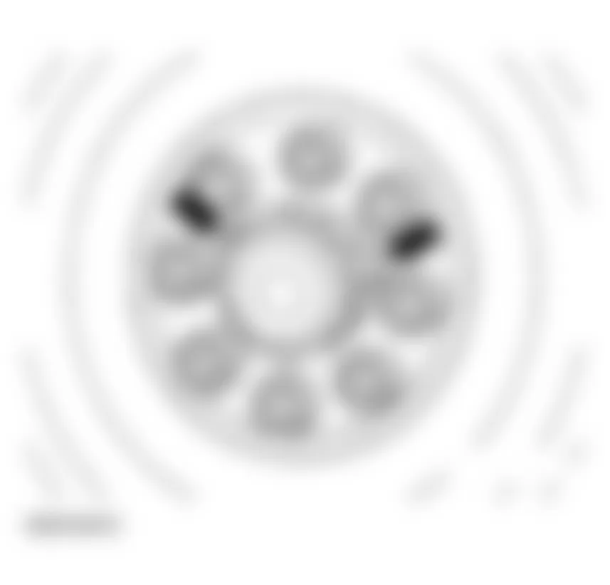
- Dual-mass flywheel: 60 Nm + 180? (1/2 turn)
- Dual-mass flywheel
- Removing and installing. See DUAL-MASS FLYWHEEL/DRIVE PLATE; INSTALLATION DIMENSIONS, REMOVING AND INSTALLING.
- Removing and installing needle bearing. See NEEDLE BEARING IN DUAL-MASS FLYWHEEL, REMOVING AND INSTALLING.
- Crankshaft bearing
- Checking axial and radial clearance. See AXIAL AND RADIAL CLEARANCE OF CRANKSHAFT, MEASURING.
- Bolt, tightening torque 10 Nm
- Oil spray jet
- For piston cooling.
- Oil seal for rear sealing flange
- Replacing. See CRANKSHAFT OIL SEALS, REPLACING.
- Bolt, tightening torque 10 Nm
- Rear sealing flange
- Gasket
- Bolt, tightening torque 25 Nm
- Screw in bolts on left and right sides finger-tight before tightening bolts on main bearing caps.
- Cylinder block
- Gasket
- Collar bolt, tightening torque 30 Nm
- Apply Loctite when installing
- Bolt, tightening torque 10 Nm
- Front sealing flange
- Expansion pins
- Crankshaft
- Checking. See AXIAL AND RADIAL CLEARANCE OF CRANKSHAFT, MEASURING.
- Chain sprocket for oil pump
- Removing and installing. See CHAIN SPROCKET FOR OIL PUMP ON CRANKSHAFT, REMOVING AND INSTALLING.
- Pistons
- Checking. See PISTONS AND PISTON RINGS, CHECKING.
- Piston rings
- Checking, see PISTONS AND PISTON RINGS, CHECKING
- Circlip for piston pin
- Piston pin
- Connecting rod
- Mark cylinder number and installation position of matching connecting rods and bearing caps before removing
- Installation position: wider, slightly convex machined surfaces on the same side
- Connecting rod bearing
- Do not interchange used bearing shells.
- Connecting rods, connecting rod bearings, see CONNECTING RODS, CONNECTING ROD BEARINGS, CHECKING
- Connecting rod bearing bolts
- Always replace
- Tightening torque: 30 Nm + 90? (1/4 turn)
- When measuring radial clearance, tighten to 20 Nm but do not turn further.
- Main bearing cap
- Marking -1- on oil pump side
- Replace bolts for main bearing caps
- Watch position of dowel sleeves
- Checking bearing clearnce, see AXIAL AND RADIAL CLEARANCE OF CRANKSHAFT, MEASURING
- Bolts for main bearing caps
- Always replace
- Tightening torque, see TIGHTENING SEQUENCE
- Tightening sequence, see TIGHTENING SEQUENCE

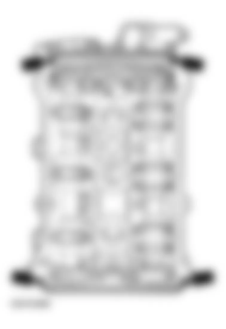
Audi allroad Quattro 2005 - Crankshaft bearing caps, installing
NOTE: Bearing -1- is at the toothed belt end; bearing -4- is at the flywheel end.
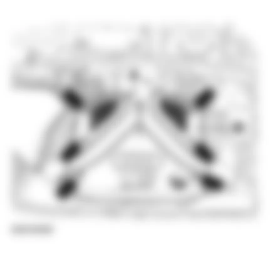
Audi allroad Quattro 2005 - Tightening sequence
- Stage 1 - Tighten all bolts in sequence shown (1 - 16) to 30 Nm.
- Stage 2 - Tighten all bolts in sequence shown (1 - 16) to 60 Nm.
- Stage 3 - Using a fixed wrench, turn all bolts in sequence shown (1 - 16) 90? further.
- Tighten bolts -A- to 25 Nm.
Audi allroad Quattro 2005 - Axial and radial clearance of crankshaft, measuring Axial clearance
NOTE: Do not interchange used bearings.
- Attach dial indicator with universal dial indicator bracket VW 387 to oil pump and bring it into contact with crank web. See Fig. 81.
- Press crankshaft against dial indicator by hand and set gauge to -0-.
- Press crankshaft away from dial indicator.
- Note reading:
Fig. 81: Audi allroad Quattro 2005 - Component Locations - Measuring Axial Clearance Of Crankshaft
Audi allroad Quattro 2005 CRANKSHAFT AXIAL CLEARANCE (END PLAY) SPECIFICATIONS
Clearance when new Wear limit 0.090 - 0.251 mm 0.28 mm
Audi allroad Quattro 2005 - Radial clearance
- Measure radial clearance with Plastigage
- Read value:
Audi allroad Quattro 2005 CRANKSHAFT RADIAL CLEARANCE SPECIFICATIONS
Clearance when new Wear limit 0.018 - 0.045 mm 0.10 mm
Audi allroad Quattro 2005 - Crankshaft oil seals, replacing A - Toothed belt end
- Remove toothed belt. See TOOTHED BELT, REMOVING AND INSTALLING.
- Remove toothed belt sprocket from crankshaft
- Pull out oil seal with oil seal extractor 3203.
- Clean contact surface and sealing surface.
NOTE: Do not lubricate sealing lip or outer circumference of seal before pressing in. - Push on seal using fitting sleeve 3202/1.
- Press in seal until flush using fitting sleeve 3265 and central bolt.

Fig. 83: Audi allroad Quattro 2005 - Component Locations - Pressing In Crankshaft Front Oil Seal

Audi allroad Quattro 2005 - B - Flywheel end
NOTE: Replace oil seal together with sealing flange.
Audi allroad Quattro 2005 - Vehicles with manual transmission
- Drain coolant. See COOLING SYSTEM, DRAINING AND FILLING .
- Remove transmission
Vehicles with four-wheel drive
See 6 SPD. MANUAL TRANSMISSION 01E .
- Remove clutch.
- With crankshaft at TDC, screw in clamping bolt 3242.
- Mark position of flywheel relative to engine -arrows-.
- Remove dual-mass flywheel.
- Remove sealing flange.
Audi allroad Quattro 2005 - Installing
- Install sealing flange.
- Install dual-mass flywheel with new bolts.
- Install clutch.
Vehicles with all-wheel drive
See 6 SPD. MANUAL TRANSMISSION 01E .
Audi allroad Quattro 2005 TIGHTENING TORQUE: DUAL-MASS FLYWHEEL
Component Tightening torques Dual-mass flywheel to crankshaft 60 Nm + 180 Degree Turn(1) Clutch to dual-mass flywheel 20 Nm
(1) Always replace securing bolts for dual-mass flywheel.
NOTE: Always replace securing bolts for dual-mass flywheel.
Audi allroad Quattro 2005 - Vehicles with automatic transmission
- Remove transmission.
See 5 SPD, AUTOMATIC TRANSMISSION 0 1V .
- Drain off coolant. See COOLING SYSTEM, DRAINING AND FILLING .
- Turn crankshaft to TDC by hand. Marks -A- and -B- must be aligned.
NOTE: Turn over the engine at the central bolt on the crankshaft. - Check position of camshafts: larger holes in securing plates on camshaft sprockets must align opposite one another on inside. If not, turn crankshaft one revolution further.
Fig. 85: Audi allroad Quattro 2005 - Component Locations - Turning Crankshaft To TDC By Hand - Remove sealing plug from cylinder block, left.
- TDC drilling in crankshaft must be visible (or able to be felt) in line with sealing plug hole.
CAUTION: Injury risk - do not turn engine while feeling for TDC drilling. - Screw clamping bolt 3242 for crankshaft into sealing plug hole and tighten.
- Mark positions of holes in drive plate, shim -1- and washer -2- in relation to crankshaft.
- Mark positions of shim -1- in front of drive plate and washer -2- behind drive plate.


Audi allroad Quattro 2005 - Installing
- Install drive plate with washer -2- and shim -1- (3.0 mm or 4.0 mm).
NOTE: - Short engines and exchange engines are supplied without a bushing in the crankshaft. On vehicles with an automatic transmission, always install a new bushing before installing the drive plate.
- Always replace drive plate securing bolts.
Fig. 87: Audi allroad Quattro 2005 - Component Locations - Installing Drive Plate With Washer
Audi allroad Quattro 2005 TIGHTENING TORQUE: AUTOMATIC TRANSMISSION DRIVE PLATE
Component Tightening torques Drive plate to crankshaft 60 Nm + 90 Degree Turn(1)
(1) Always replace securing bolts for drive plate.
NOTE: Always replace securing bolts for drive plate.
- Measure distance -a- at three points and calculate average value.
- Distance -a- = approx. 29.9 mm.
- Install a different shim if necessary.
NOTE: Before installing the transmission, check that the dowel sleeves for locating engine/transmission are installed in the engine flange.
- Install transmission.
See 5 SPD, AUTOMATIC TRANSMISSION 01V .
Audi allroad Quattro 2005 - Dual-mass flywheel/drive plate; installation dimensions, removing and installing
Audi allroad Quattro 2005 - A - Flywheel Removing
- Remove transmission.
Vehicles with four-wheel drive
See 6 SPD. MANUAL TRANSMISSION 01E .
- Remove clutch.
- With crankshaft at TDC, screw in clamping bolt 3242.
- Mark position of flywheel relative to engine -arrows-.
- Unscrew bolts (bolts must be replaced).
NOTE: The needle bearing is located in the flywheel and must be pressed in if a new flywheel is installed. See NEEDLE BEARING IN DUAL-MASS FLYWHEEL, REMOVING AND INSTALLING.
Audi allroad Quattro 2005 - Installing
- Install dual-mass flywheel.
NOTE: Always replace flywheel securing bolts.
- Install clutch.
Vehicles with all-wheel drive.
See 6 SPD. MANUAL TRANSMISSION 01E .
- Install transmission.
Vehicles with all-wheel drive
See 6 SPD. MANUAL TRANSMISSION 01E .
Audi allroad Quattro 2005 TIGHTENING TORQUE: DUAL-MASS FLYWHEEL
Component Tightening torques Dual-mass flywheel to crankshaft 60 Nm + 180 Degree Turn Clutch to dual-mass flywheel 20 Nm
() Always replace securing bolts for dual-mass flywheel.
Audi allroad Quattro 2005 - B - Drive plate Removing
- Remove transmission.
See 5 SPD, AUTOMATIC TRANSMISSION 01V .
- Turn crankshaft to TDC by hand. Marks -A- and -B- must be aligned.
NOTE: Turn over the engine at the central bolt on the crankshaft. - Check position of camshafts: larger holes in securing plates on camshaft sprockets must align opposite one another on inside. If not, turn crankshaft one revolution further.
- Remove sealing plug from cylinder block, left.
Fig. 90: Audi allroad Quattro 2005 - Component Locations - Turning Crankshaft To TDC By Hand

TDC drilling in crankshaft must be visible (or able to be felt) in line with the sealing plug hole.
CAUTION: Injury risk - do not turn engine while feeling for TDC drilling.
- Screw clamping bolt 3242 for crankshaft into sealing plug hole and tighten.
- Mark positions of holes in drive plate, shim -1- and washer -2- in relation to crankshaft.
- Mark positions of shim -1- in front of drive plate and washer -2- behind drive plate.

Audi allroad Quattro 2005 - Installing
- Install drive plate with washer -2- and shim -1- (3.0 mm or 4.0 mm).
NOTE:
Fig. 92: Audi allroad Quattro 2005 - Component Locations - Installing Drive Plate With Washer
Audi allroad Quattro 2005 TIGHTENING TORQUE: DRIVE PLATE
Component Tightening torques Drive plate to crankshaft 60 Nm + 90 Degree Turn(1)
(1) Always replace drive plate securing bolts.
- Measure distance -a- at three points and calculate average value.
- Distance -a- = approx. 12.3 mm.
- Install a different shim if necessary.
NOTE: Before installing the transmission, check that the dowel sleeves for locating engine/transmission are installed in the engine flange.
- Install transmission.
See 5 SPD, AUTOMATIC TRANSMISSION 01V .
Audi allroad Quattro 2005 - Needle bearing in dual-mass flywheel, removing and installing
- Pull out needle bearing with puller, such as KUKKO 21/2 and KUKKO 22/1.
- Drive in with drift 3264.
Audi allroad Quattro 2005 - Pistons and piston rings, checking Pistons
Position: arrow on piston crown must always face in direction of travel.
- Mark cylinder number on piston crown with waterproof felt pen.
NOTE: Do not use a center-punch or similar, as pistons have a special coating.
Fig. 95: Audi allroad Quattro 2005 - Component Locations - Marking Cylinder Number On Piston Crown
Audi allroad Quattro 2005 - Checking piston diameter
- Measure pistons approx. 10 mm from bottom of skirt, at 90? to piston pin axis.
- Difference between actual and nominal diameter: not more than 0.04 mm.
Fig. 96: Audi allroad Quattro 2005 - Component Locations - Checking Piston Diameter

Audi allroad Quattro 2005 - Ring-to-groove clearnce
Audi allroad Quattro 2005 PISTON RING-TO-GROOVE CLEARNCE
Clearance when new Wear limit 0.02 - 0.08 mm 0.10 mm
Fig. 97: Audi allroad Quattro 2005 - Component Locations - Checking Piston Ring Side Clearance

Audi allroad Quattro 2005 - Checking piston ring gap
- Push ring in squarely to a position approx. 15 mm from bottom end of cylinder.
Audi allroad Quattro 2005 PISTON RING GAP SPECIFICATIONS
Piston ring Gap when new Wear limit 1 0.35 - 0.50 mm 1.0 mm 2 0.50 - 0.70 mm 1.4 mm 3 0.25 - 0.50 mm 0.8 mm
Fig. 98: Audi allroad Quattro 2005 - Component Locations - Checking Piston Ring End Gap
Audi allroad Quattro 2005 - Cylinder bores, checking
- Measure bores at three points in both directions: across engine -A- and in line with crankshaft -B-.
- Use internal dial indicator 50 - 100 mm.
- Difference between actual and nominal diameter: not more than 0.08 mm.
Audi allroad Quattro 2005 - Piston and cylinder dimensions
Audi allroad Quattro 2005 PISTON AND CYLINDER BORE DIMENSIONS
Honing dimension Piston dia. Cyl. bore dia. Basic dimension 80.95 mm 81.01 mm
Fig. 99: Audi allroad Quattro 2005 - Component Locations - Cylinder Bore Checking Points
NOTE: Replacement pistons are only available with basic dimension.
Audi allroad Quattro 2005 - Connecting rods, connecting rod bearings, checking
NOTE:
- Before removing, mark positions of connecting rod bearing caps with a felt pen or similar.
Audi allroad Quattro 2005 - Checking radial clearance
- Remove connecting rod bearing cap. Clean bearing cap and bearing journal.
- Place a length of Plastigage corresponding to width of bearing on the bearing journal or bearing shell.
- Install connecting rod bearing cap and tighten to 20 Nm. Do not rotate crankshaft.
- Remove connecting rod bearing cap again.
- Compare width of Plastigage with calibrated scale.
Audi allroad Quattro 2005 CONNECTING ROD BEARING RADIAL CLEARANCE
Clearance when new Wear limit 0.015 - 0.062 mm 0.12 mm - Install new connecting rod bearing bolts.
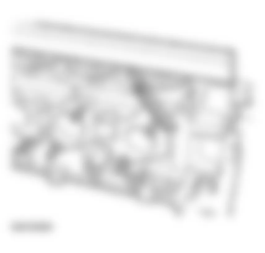
Audi allroad Quattro 2005 - Engine - Cylinder head, Valvetrain Valve gear, servicing
NOTE:
NOTE: The following list refers to items in Fig. 101.
- Double bearing cap
- Lightly coat with sealant 454 300 A2 before installing. See INSTALLING.
- Exhaust camshaft bearing cap
- With connection for oil feed line
- Watch position of dowel sleeve
- Note installation position and numbering. See CAMSHAFTS AND CAMSHAFT ADJUSTERS, REMOVING AND INSTALLING.
- Lightly coat last bearing cap (after the chain) with sealant D454 300 A2 before installing
- 10 Nm
- Exhaust camshaft
- Checking axial clearance. See CAMSHAFT AXIAL CLEARANCE, CHECKING
- Removing and installing. See CAMSHAFTS AND CAMSHAFT ADJUSTERS, REMOVING AND INSTALLING.
- Check radial clearance with in Plastigage? (lifters removed) Wear limit: 0.1 mm Runout: 0.01 mm (maximum)
- Cap
- Always replace
- Inlet camshaft bearing cap
- With connection for oil feed line
- Note installation position and numbering. See CAMSHAFTS AND CAMSHAFT ADJUSTERS, REMOVING AND INSTALLING.
- Inlet camshaft
- Checking axial clearance. See CAMSHAFT AXIAL CLEARANCE, CHECKING.
- Removing and installing. See CAMSHAFTS AND CAMSHAFT ADJUSTERS, REMOVING AND INSTALLING.
- Check radial clearance with Plastigage? (lifters removed)
Wear limit: 0.1 mm
Run-out: 0.01 mm (maximum)
- Drive chain
- Installing. See CAMSHAFTS AND CAMSHAFT ADJUSTERS, REMOVING AND INSTALLING.
- 10 Nm
- Mechanical camshaft adjuster
- With camshaft adjustment valve -N205
- Secure with special tool 3366 before removing. See CAMSHAFTS AND CAMSHAFT ADJUSTERS, REMOVING AND INSTALLING.
- Hydraulic bucket lifter
- Notes, see HYDRAULIC VALVE LIFTERS, CHECKING
- Removing and installing with cylinder head installed, see CAMSHAFTS AND CAMSHAFT ADJUSTERS, REMOVING AND INSTALLING
- Valve keepers
- Valve spring plate
- Valve spring
- Valve stem seal
- Replacing with cylinder head installed, see VALVE STEM SEALS, REPLACING
- Rubber/metal gasket
- Always replace
- Seal
- Always replace
- Cylinder head
- Checking for distortion, see CYLINDER HEAD, CHECKING FOR DISTORTION
- Reworking, see CYLINDER HEAD, REWORKING
- Exhaust valve
- Inlet valve
- Oil seal (Hall sensor end)
- Always replace. See OIL SEALS IN CYLINDER HEADS, REPLACING.
- Rotor for Hall sensor
- Note position (notch on camshaft)
- Washer
- Conical
- 25 Nm
- Hall sensor
- 10 Nm
- 30 Nm +180? (1/2 turn)
- Camshaft sprocket
- Oil seal (toothed belt end)
- Replacing, see OIL SEALS IN CYLINDER HEADS, REPLACING
Fig. 101: Audi allroad Quattro 2005 - Component Locations - Exploded View Of Cylinder Head Assembly

Audi allroad Quattro 2005 - Sealing end points of joints between bearing caps and cylinder head
- Carefully apply small quantity of sealant D 454 300 A2 at four end points of sealing surfaces on cylinder head -arrows-, using a small screwdriver.

Audi allroad Quattro 2005 - Oil seals in cylinder heads, replacing Oil seal for camshaft drive (left and right cylinder heads)
NOTE: If the oil seal on one side is leaking it is advisable to replace the seals on both sides.
- Remove ribbed belt. See RIBBED BELT, REMOVING AND INSTALLING.
- Remove toothed belt. See TOOTHED BELT, REMOVING AND INSTALLING.
- Remove rear toothed belt guard.
- Remove oil seal with oil seal extractor 3240.
- Clean contact surface and sealing surface.
- Do not apply oil to sealing lip or outer circumference of seal.
- Install guide sleeve 3241/2 (from tool set 3241) onto camshaft.
- Press seal flush into cylinder head using press sleeve 3241/1 and bolt 3241/3.
Fig. 104: Audi allroad Quattro 2005 - Component Locations - Installing Oil Seal Into Cylinder Head

Audi allroad Quattro 2005 - Oil seal at Hall sensor (right cylinder head)
- Remove intake hose going to air cleaner (arrows).
- Remove bolts -arrows- and remove engine cover panel -C-.
Fig. 106: Audi allroad Quattro 2005 - Component Locations - Removing Engine Cover Panel - Remove pressure line -1- (right side).
Fig. 107: Audi allroad Quattro 2005 - Component Locations - Removing Pressure LineNOTE: Watch position of retaining strip -2-. - Unbolt Hall sensor housing (10 Nm).
- Remove bolt securing Hall sensor rotor (20 Nm) and carefully pry off rotor with a screwdriver.
- Screw in bolt from oil seal extractor 2085/1. See Fig. 108.
- Disconnect out seal with oil seal extractor 2085 and bolt 2085/1.
- Clean contact surface and sealing surface.
- Do not apply oil to sealing lip or outer circumference of seal before installing.
- Install guide sleeve (from tool set 3241) onto camshaft.
- Press in seal until flush using press sleeve 3241/1 and bolt 3241/3.


Audi allroad Quattro 2005 - Installing
Install in reverse sequence.
NOTE: When installing Hall sensor rotor, make sure that locating lug engages in slot in camshaft.

Audi allroad Quattro 2005 - Removing oil seal at Hall sensor (left cylinder head)
- Detach coolant reservoir -arrows- and move it clear to side.
NOTE: Leave coolant hoses connected. - Disconnect electrical connector from coolant level monitor.
- Move wiring harness clear at bulkhead
- Unbolt bracket -arrows- for plug connectors on bulkhead and move clear to side.
Fig. 112: Audi allroad Quattro 2005 - Component Locations - Removing Plug Connectors On Bulkhead - Unbolt Hall sensor housing (10 Nm).
- Unbolt Hall sensor rotor (20 Nm) and carefully pry off rotor using a screwdriver.
- Screw in bolt from 2085/1 oil ring extractor.
- Disconnect out seal with oil seal extractor 2085 and bolt 2085/1.
- Clean contact surface and sealing surface.
NOTE: Do not apply oil to sealing lip or outer circumference of seal before installing. - Install guide sleeve (from tool set 3241) onto camshaft.
- Press in seal until flush using press sleeve 3241/1 and bolt 3241/3.


Audi allroad Quattro 2005 - Installing
Install in reverse sequence.
NOTE: When installing Hall sensor rotor, make sure that locating lug engages in slot in camshaft.

Audi allroad Quattro 2005 - Rear oil seal and sealing flange (left cylinder head)
NOTE: Rear sealing flange and oil seal on left-hand cylinder head must be replaced together as follows:
- Remove bolts -arrows- and remove engine cover panels -A and C-.
Fig. 116: Audi allroad Quattro 2005 - Component Locations - Removing Engine Cover Panels - Remove air duct -arrows-.
Fig. 117: Audi allroad Quattro 2005 - Component Locations - Removing Air Duct - Remove coolant reservoir -arrows- and move it clear to the side.
NOTE: Leave coolant hoses connected. - Disconnect electrical connector from coolant level monitor.
- Move wiring harness clear at bulkhead.
Fig. 118: Audi allroad Quattro 2005 - Component Locations - Removing Coolant Reservoir - Unbolt bracket -arrows- for plug connectors on bulkhead and move clear to side.
- Unbolt Hall sensor housing (10 Nm).
- Remove bolt securing Hall sensor rotor (20 Nm) and carefully pry off rotor using a screwdriver.
Fig. 119: Audi allroad Quattro 2005 - Component Locations - Removing Connectors On Bulkhead - Remove cover panel from cylinder head cover (cylinder bank 4-6).
- Release hose clamp -arrow-. See Fig. 120.
- Remove upper section of intake line -1-.
- Disconnect hose -2-.
- Plug lower section of intake line.
- Disconnect hose -1-(arrow).
Fig. 121: Audi allroad Quattro 2005 - Component Locations - Disconnecting Hose - Remove bolt securing toothed belt guard from cylinder head cover.
- Disconnect plug connectors off ignition coils.
- Disconnect crankcase breather off cylinder head cover.
- Remove cylinder head cover.
- Remove double bearing cap -arrows-.
- Take out oil seal and sealing flange.
- Clean contact surfaces and sealing surfaces of double bearing cap.
Fig. 122: Audi allroad Quattro 2005 - Component Locations - Removing Double Bearing Cap - Apply a thin coating of sealant, Part No. 454 300 A2, to shaded areas on double bearing cap (see illustration), install bearing cap and tighten bolts to 10 Nm.
- Install guide sleeve (from tool set 3241) onto camshaft.
- Press in oil seal until flush using press sleeve 3241/1 and bolt 3241/3.
- Carefully knock in sealing flange against stop using 3202 and a plastic hammer.


Audi allroad Quattro 2005 - Installing
Install in reverse sequence; note the following points:
- Seal end points of joints between bearing caps and cylinder head.
- Before installing cylinder head cover and gasket, carefully apply a small quantity of sealant D 454 300 A2 at four end points of sealing surfaces on cylinder head -arrows-, using a small screwdriver.
Audi allroad Quattro 2005 - Cylinder head covers, removing and installing Removing and installing left cylinder head cover Removing
- Remove bolts -arrows- and remove engine cover panels -A and C-.
Fig. 126: Audi allroad Quattro 2005 - Component Locations - Removing Engine Cover Panels - Remove air duct -arrows-.
Fig. 127: Audi allroad Quattro 2005 - Component Locations - Removing Air Duct - Remove coolant reservoir -arrows- and move it clear to side.
NOTE: Leave coolant hoses connected. - Disconnect electrical connector from coolant level monitor.
- Remove cover panel from cylinder head cover (cylinder bank 4-6).
Fig. 128: Audi allroad Quattro 2005 - Component Locations - Removing Coolant Reservoir - Release hose clamp -arrow-. See Fig. 129.
- Remove intake line -1-.
- Disconnect hose -2-.
- Detach water line -3-.
NOTE: Plug lower section of intake line.
Fig. 129: Audi allroad Quattro 2005 - Component Locations - Removing Hose Clamp And Intake Line - Disconnect from hose -1-
Fig. 130: Audi allroad Quattro 2005 - Component Locations - Disconnecting Hose - Disconnect plug connectors from ignition coils.
- Disconnect crankcase breather from cylinder head cover.
- Remove ignition coils.
- Remove cylinder head cover.


Audi allroad Quattro 2005 - Installing
Install in reverse sequence; note the following points:
- Seal end points of joints between bearing caps and cylinder head.
- Before installing cylinder head cover and gasket, carefully apply a small quantity of sealant D 454 300 A2 at four end points of sealing surfaces on cylinder head -arrows-, using a small screwdriver.
Audi allroad Quattro 2005 - Right cylinder head cover, removing and installing Removing
- Remove bolts -arrows- and remove engine cover panels -A...C-.
- Remove cover above air cleaner.
Fig. 132: Audi allroad Quattro 2005 - Component Locations - Removing Engine Cover Panels - Remove air duct -arrows-.
Fig. 133: Audi allroad Quattro 2005 - Component Locations - Removing Air DuctWARNING: Fuel system is under pressure. Before opening the system, place a cloth around the connection. Then release pressure by carefully loosening the connection. - Disconnect fuel supply line and fuel return line -1- and -2-, and move fuel lines clear.
- Disconnect hose from EVAP valve -3-. See Fig. 134.
- Disconnect electrical connector -1- from mass air flow (MAF) sensor.
- Disconnect electrical connectors -2- from ignition output stages, and move wiring clear.
- Remove air cleaner.
- Remover cover panel from right-hand cylinder head cover -arrows-.
- Disconnect hose -1-.
- Disconnect hose -2-.
- Detach upper section of intake line -3-.
NOTE: Plug lower section of intake line. - Remove bolt securing toothed belt guard from cylinder head cover.
- Disconnect electrical connectors from ignition coils.
- Disconnect crankcase breather off cylinder head cover.
- Remove ignition coils.
- Remove cylinder head cover.


Audi allroad Quattro 2005 - Installing
Install in reverse sequence; note the following points.
- Seal end points of joints between bearing caps and cylinder head.
- Before installing cylinder head cover and gasket, carefully apply a small quantity of sealant D 454 300 A2 at four points of sealing surfaces on cylinder head -arrows-, using a small screwdriver.

Audi allroad Quattro 2005 - Cylinder head, removing and installing Removing and installing left cylinder head
NOTE:
Audi allroad Quattro 2005 - Removing
- Remove engine. See ENGINE, REMOVING AND INSTALLING.
- Disconnect electrical connector from air recirculation valve -2-.
- Disconnect electrical connector from camshaft timing control -1- (cylinder bank 4..6). See Fig. 140.
- Disconnect electrical connectors from injectors -2- (cylinder bank 4..6).
- Disconnect electrical connectors from ignition coils -3- and move wiring harness clear (cylinder bank 4..6).
- Disconnect crankcase breather -4- from cylinder head cover (cylinder bank 4..6).
- Remove ignition coils.
- Disconnect electrical connectors from injectors -2- (cylinder bank 1..3).
- Disconnect hose -5- going to turbocharger intake side.
- Unclip solenoid valve for charge air pressure control -1-.
- Disconnect connector from EVAP valve -2-.
- Disconnect connector from throttle unit -1-. See Fig. 143.
- Disconnect connector from charge air sensor -2-.
- Disconnect crankcase breather -3-.
- Disconnect connector from intake air temperature sensor -4-.
- Remove pressure lines-1-. See Fig. 144.


NOTE: Watch position of retaining strips -2-.
Fig. 144: Audi allroad Quattro 2005 - Component Locations - Removing Pressure Lines

- Remove tensioner -1- for ribbed belt.
- Remove toothed belt guards -2- (left and right).
- Remove toothed belt guard -3- (center).
Fig. 145: Audi allroad Quattro 2005 - Component Locations - Removing Tensioner - Turn crankshaft to TDC by hand. Marks -A- and -B- must be aligned.


NOTE: Turn over the engine at the central bolt on the crankshaft.
- Check position of camshafts: larger holes in securing plates on camshaft sprockets must align opposite one another on inside. If not, turn crankshaft one revolution further.
- Remove sealing plug from cylinder block, left.
- TDC drilling in crankshaft must be visible (or able to be felt) in line with sealing plug hole.
- Screw clamping bolt 3242 for crankshaft into sealing plug hole and tighten.
- Remove vibration damper on crankshaft

Fig. 148: Audi allroad Quattro 2005 - Component Locations - Removing Vibration Damper On Crankshaft

NOTE: The central bolt does not have to be loosened to remove the vibration damper.
- Remove idler wheel for ribbed belt -arrows-.
- Remove toothed belt guard behind vibration damper -arrows-.

NOTE:
- Using a hex key, turn toothed belt tensioning roller -1- clockwise 8 mm in direction of arrow until tensioning lever -2- compresses tensioning element -3- sufficiently to enable a 2 mm dia. spring pin to be installed in drilling and in plunger.
- Insert spring pin and release toothed belt tensioning roller.
- Use spring pin from 2024 A.
- Insert camshaft clamp 3391 in securing plates of two camshafts.
- Loosen both camshaft bolts and remove approx. 5 turns.
- Take out camshaft clamp 3391.
- Disconnect both camshaft sprockets with special tool T40001.
Fig. 151: Audi allroad Quattro 2005 - Component Locations - Disconnecting Camshaft Sprockets - Unbolt rear left toothed belt guard -arrows-.
- Detach intake manifold using special tool 3249.
Fig. 152: Audi allroad Quattro 2005 - Component Locations - Removing Rear Left Toothed Belt Guard - Unbolt cylinder head lifting bracket with coolant line -arrows- from cylinder head.
Fig. 153: Audi allroad Quattro 2005 - Component Locations - Removing Cylinder Head Lifting Bracket - Unbolt water line -1- and disconnect it towards rear. See Fig. 154.
- Unbolt bracket -2- from cylinder head.
- Remove heat sensor -2-.
Fig. 154: Audi allroad Quattro 2005 - Component Locations - Removing Water Line And Heat Sensor - Unbolt turbocharger -1- from exhaust manifold (3 bolts).
Fig. 155: Audi allroad Quattro 2005 - Component Locations - Removing Turbocharger - Unbolt coolant line at front of cylinder head -arrows-.
- Unbolt cylinder head cover.
- Loosen and remove cylinder head bolts in opposite sequence to tightening sequence using special tool 3452 (Polidrive).
- Carefully lift off cylinder head.


NOTE: Use special tool 3452 together with a normal commercial 10 mm socket when removing and installing.
Fig. 157: Audi allroad Quattro 2005 - Component Locations - Identifying Special Tool
Audi allroad Quattro 2005 - Installing
NOTE:
When installing a new cylinder head:
- Screw in centering pin for intake manifold.
The cylinder head supplied as a replacement part can be used on both sides (left or right). But a sealing cap (core plug) must be installed in the front end of the cylinder head in each case.
- Coat outside circumference of sealing cap (core plug) with sealant AMV 188 001 02.
- Using drift VW 295, knock in sealing cap (core plug) until outside rim is flush with end of the chamfer in cylinder head.
Fig. 158: Audi allroad Quattro 2005 - Component Locations - Locating Core Plug In Cylinder Head - Before installing cylinder head in position, turn crankshaft and camshafts to TDC of No. 3 cylinder.
- Install cylinder head gasket on dowel sleeves. Marking "oben" (top) or part number must face towards cylinder head.
- Install cylinder head, insert cylinder head bolts and tighten finger-tight.
- Tighten NEW cylinder head bolts in two stages in sequence (Fig. 159), as follows: Audi allroad Quattro 2005 - Component Locations -
- Stage 1 = 60 Nm.
- Stage 2 = turn a further 1/2 turn (180?) with a rigid wrench (turning 2 x 90? is also permissible).
It is not necessary to torque down cylinder head bolts again after repairs have been completed.
- Seal end points of joints between bearing caps and cylinder head.
- Before installing cylinder head cover and gasket, carefully apply a small quantity of sealant D 454 300 A2 at four end points of sealing surfaces on cylinder head -arrows-, using a small screwdriver.
Audi allroad Quattro 2005 - Tightening torques
Audi allroad Quattro 2005 TIGHTENING TORQUES: LEFT CYLINDER HEAD
Component Nm Bolts-M6 10 Bolts-M8 20 Camshaft bearing caps and camshaft adjuster 10 Exhaust manifold to cylinder head 25 Front exhaust line to exhaust manifold 25 Oxygen sensor 50 Spark plugs 25 Toothed belt sprocket to camshaft 55 Intake manifold to cylinder head 10 Cylinder head cover 10
Audi allroad Quattro 2005 - Right cylinder head, removing and installing
NOTE:
Audi allroad Quattro 2005 - Removing
- Remove engine. See ENGINE, REMOVING AND INSTALLING.
- Disconnect electrical connector from air recirculation valve -2-.
- Remove cover panel from right-hand cylinder head cover -arrows-.
- Disconnect hose -1-.
- Disconnect hose -2-. See Fig. 163.
- Unbolt upper section of intake line -3-.


Fig. 163: Audi allroad Quattro 2005 - Component Locations - Disconnecting Hose

NOTE: Plug lower section of intake line.
- Disconnect connectors from injectors -2- (cylinder bank 4..6).
- Disconnect connector for camshaft timing control -1- (cylinder bank 1..3).
- Disconnect connectors from injectors -2-(cylinder bank 1..3).
- Disconnect connectors from ignition coils -3- and move wiring harness clear (cylinder bank 1..3).
- Disconnect crankcase breather -4- from cylinder head cover (cylinder bank 1..3).
- Disconnect hose -5- going to turbocharger intake side.
- Remove ignition coils.
- Unclip solenoid valve for charge pressure control -1-.
- Disconnect connector from EVAP valve -2-.
- Disconnect connector from throttle unit -1-. See Fig. 167.
- Disconnect connector from charge air sensor -2-.
- Disconnect crankcase breather -3-.
- Disconnect connector from intake air temperature sensor -4-.
- Disconnect connector -5- from Hall sensor.
- Remove pressure lines -1-.


NOTE: Watch position of retaining strips -2-.
Fig. 168: Audi allroad Quattro 2005 - Component Locations - Removing Pressure Lines

- Remove tensioner -1- for ribbed belt.
- Remove toothed belt guards -2- (left and right).
- Remove toothed belt guard -3- (center).
- Turn crankshaft to TDC by hand. Marks -A- and -B- must be aligned.


NOTE: Turn over the engine at the central bolt on the crankshaft.
- Check position of camshafts: larger holes in securing plates on camshaft sprockets must align opposite one another on inside. If not, turn crankshaft one revolution further.
- Remove sealing plug from cylinder block, left.
- TDC drilling in crankshaft must be visible (or able to be felt) in line with sealing plug hole.
- Screw clamping bolt 3242 for crankshaft into sealing plug hole and tighten.
- Remove vibration damper on crankshaft.

NOTE: The central bolt does not have to be loosened to remove the vibration damper.
Fig. 172: Audi allroad Quattro 2005 - Component Locations - Removing Vibration Damper On Crankshaft
- Remove idler wheel for ribbed belt -arrows-.
- Remove toothed belt guard behind vibration damper -arrows-.

NOTE:
- Using a hex key, turn toothed belt tensioning roller -1- clockwise 8 mm in direction of arrow until tensioning lever -2- compresses tensioning element -3- sufficiently to enable a 2 mm dia. spring pin to be installed in drilling and in plunger.
- Insert spring pin and release toothed belt tensioning roller.
- Use spring pin from 2024 A.
- Insert camshaft clamp 3391 in securing plates of two camshafts.
- Loosen both camshaft bolts and remove approx. 5 turns.
- Take out camshaft clamp 3391.
- Disconnect both camshaft sprockets with special tool T40001.
Fig. 175: Audi allroad Quattro 2005 - Component Locations - Disconnecting Camshaft Sprockets - Unbolt rear right toothed belt guard -arrows-.
- Detach intake manifold using special tool 3249.
Fig. 176: Audi allroad Quattro 2005 - Component Locations - Removing Rear Right Toothed Belt Guard - Unbolt water line -1- and disconnect toward rear.
Fig. 177: Audi allroad Quattro 2005 - Component Locations - Unbolting Water Line - Detach line -arrow- from cylinder head.
Fig. 178: Audi allroad Quattro 2005 - Component Locations - Disconnecting Line From Cylinder Head - Remove turbocharger -arrows-.
Fig. 179: Audi allroad Quattro 2005 - Component Locations - Removing Turbocharger - Unbolt cylinder head cover.
- Loosen and remove cylinder head bolts in opposite sequence to tightening sequence using special tool 3452 (Polidrive).
- Carefully lift off cylinder head.


NOTE: Use special tool 3452 together with a normal commercial 10 mm socket when removing and installing.
Fig. 180: Audi allroad Quattro 2005 - Component Locations - Identifying Special Tool

Audi allroad Quattro 2005 - Installing
NOTE:
When installing a new cylinder head:
- Screw in centering pin for intake manifold.
The cylinder head supplied as a replacement part can be used on both sides (left or right). But a sealing cap (core plug) must be installed in the front end of the cylinder head in each case.
- Coat outside circumference of sealing cap (core plug) sealant AMV 188 001 02.
- Using drift VW 295, knock in sealing cap (core plug) until outside rim is flush with end of chamfer in cylinder head.
Fig. 181: Audi allroad Quattro 2005 - Component Locations - Locating Core Plug In Cylinder Head - Before installing cylinder head in position, turn crankshaft and camshafts to TDC of No. 3 cylinder.
- Install cylinder head gasket on dowel sleeves. Marking "oben" (top) or part number must face towards cylinder head.
- Install cylinder head, insert cylinder head bolts and tighten finger-tight.
- Tighten NEW cylinder head bolts in two stages in sequence (Fig. 182), as follows: Audi allroad Quattro 2005 - Component Locations -
- Stage 1 = 60 Nm.
- Stage 2 = turn a further 1/2 turn (180?) with a box wrench (turning 2 x 90? is also permissible).
It is not necessary to torque down cylinder head bolts again after repairs have been completed.
- Seal end points of joints between bearing caps and cylinder head.
- Before installing cylinder head cover and gasket, carefully apply a small quantity of sealant D 454 300 A2 at four end points of sealing surfaces on cylinder head -arrows-, using a small screwdriver.

Audi allroad Quattro 2005 - Tightening torques
Audi allroad Quattro 2005 TIGHTENING TORQUES: RIGHT CYLINDER HEAD
Component Nm Bolts - M6 10 Bolts - M8 20 Camshaft bearing caps and camshaft adjuster 10 Exhaust manifold to cylinder head 25 Front exhaust pipe to exhaust manifold 25 Oxygen sensor 50 Spark plugs 25 Toothed belt sprocket to camshaft 55 Intake manifold to cylinder head 10 Cylinder head cover 10
Audi allroad Quattro 2005 - Cylinder head, checking for distortion
- Measure at several points with straightedge.
- Maximum permissible distortion: 0.1 mm.
Audi allroad Quattro 2005 - Cylinder head, reworking
- Reworking the cylinder head (skimming) is only permissible down to a minimum dimension of a =139.25 mm.
Audi allroad Quattro 2005 - Compression, checking Test requirements
- Engine oil temperature at least 30?C.
- Battery fully charged.
Audi allroad Quattro 2005 - Procedure
- Remove bolts -arrows- and remove engine cover panels A To C.
Fig. 186: Audi allroad Quattro 2005 - Component Locations - Removing Engine Cover Panels - Remove air duct -arrows-.
Fig. 187: Audi allroad Quattro 2005 - Component Locations - Removing Air Duct - Remove coolant reservoir -arrows- and move it clear to side.


NOTE: Leave coolant hoses connected.
- Disconnect connector from coolant level monitor.
- Remove cover panel from cylinder head cover (cylinder bank 4-6).
Fig. 188: Audi allroad Quattro 2005 - Component Locations - Removing Coolant Reservoir - Release hose clamp -arrow-. See Fig. 189.
- Remove intake line -1-.
- Disconnect hose -2-.
- Detach water line -3-.

NOTE: Plug lower section of intake line.
Fig. 189: Audi allroad Quattro 2005 - Component Locations - Removing Hose Clamp And Intake Line

- Disconnect hose -1-.
WARNING: Fuel system is under pressure. Before opening the system, place a cloth around the connection. Then release pressure by carefully loosening the connection.
Fig. 190: Audi allroad Quattro 2005 - Component Locations - Disconnecting Hose

- Disconnect fuel supply line and fuel return line -1- and -2-, and move fuel lines clear.
- Disconnect hose from EVAP valve -3-.
- Disconnect connector -1- from mass air flow (MAF) sensor.
- Disconnect connectors -2- from ignition output stages, and move wiring clear.
- Remove air cleaner.
- Remover cover panel from right-hand cylinder head cover -arrows-.
- Disconnect hose -1-. See Fig. 194.
- Disconnect hose -2-.
- Detach upper section of pressure line -3-.


NOTE: Plug lower section of pressure line.
- Disconnect crankcase breathers from cylinder head covers.
- Disconnect plug connectors from ignition coils.
- Remove ignition coils.
- Remove spark plugs.
- Disconnect connectors from all 6 injectors.
- Remove fuse No. 28 (for fuel pump).
- Disconnect 5-pin connector at power output stage of ignition coils.
- Use compression tester VAG 1381 or VAG 1763.
- Open throttle fully.
- Operate starter until pressure reading on tester no longer rises.
Audi allroad Quattro 2005 - Compression pressure values
Audi allroad Quattro 2005 ENGINE COMPRESSION PRESSURE VALUES
New Wear limit Max. permissible difference between cylinders 9-13 bar 7 bar 3 bar
Audi allroad Quattro 2005 - Installing
Install in reverse sequence; note the following points.
- Install fuse No. 28 (for fuel pump).
- Erase Diagnostic Trouble Code (DTC) memory.
NOTE: DTCs will have been stored in the memory because the connector to the Hall sensor has been disconnected. Therefore check and erase the DTC memory after the test.
Audi allroad Quattro 2005 - Tightening torques
Audi allroad Quattro 2005 TIGHTENING TORQUES: IGNITION COILS & SPARK PLUGS
Component Nm Ignition coils to cylinder head 10 Spark plugs in cylinder head 30
Audi allroad Quattro 2005 - Sealing cap (core plug) in cylinder head, installing
The cylinder head supplied as a replacement part can be used on both sides (left or right). But a sealing cap (core plug) must be installed in the front end of the cylinder head in each case.
- Coat outside circumference of sealing cap (core plug) with sealant AMV 188 001 02.
- Using drift VW 295, knock in sealing cap (core plug) until outside rim is flush with end of chamfer in cylinder head.
Fig. 195: Audi allroad Quattro 2005 - Component Locations - Locating Core Plug In Cylinder Head

Audi allroad Quattro 2005 - Camshaft adjustment function, checking Special tools and equipment
- VAS 5051 with VAG 5051/1
or
- VAG 1551 with VAG 1551/3A
Audi allroad Quattro 2005 - Test requirement
- Coolant Temperature at least 80?C.
Fig. 196: Audi allroad Quattro 2005 - Component Locations - Identifying Special Service Tool
WARNING:
Audi allroad Quattro 2005 - Test sequence
- Connect VAS 5051 tester or VAG 1551 scan tool and select control module for engine electronics using "address word" 01 Engine must run at idle.
When indicated on display

- Press buttons -0- and -4- to select "Initiate basic setting" and press -Q- button to confirm input.
When indicated on display

- Press buttons -0-, -9- and -4- to select "display group number 094" and press -Q- button to confirm input.
When indicated on display

- Camshaft adjustment is checked for function.
- Increase engine speed to above 2000 RPM.
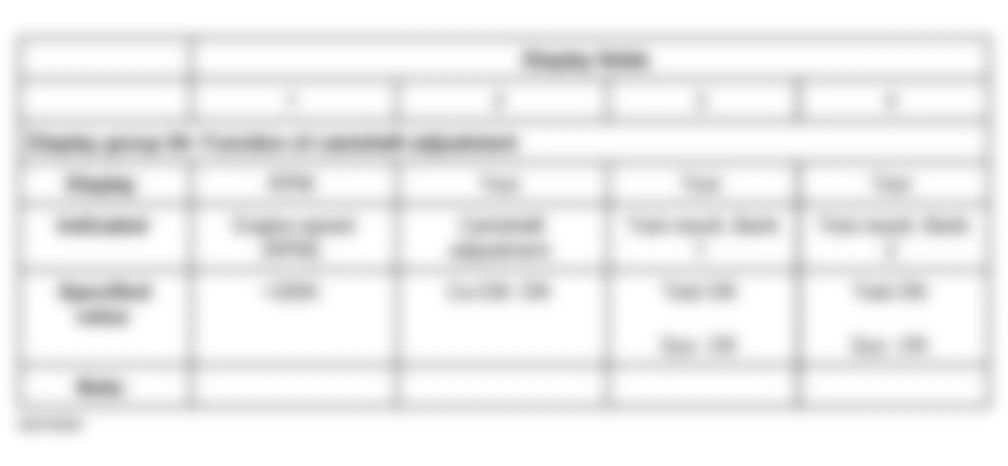
If "not OK" is indicated in display field 3 and/or 4:
- Check solenoid valve for camshaft adjustment.
Audi allroad Quattro 2005 - Solenoid valve for camshaft adjustment, checking Special tools and equipment
- VAG 1526A
- VAG 1527B
- VAG 1594A
- VAG 1598/31
- VAS 5051
- or
- VAG 1551 with VAG 1551/3A
Fig. 201: Audi allroad Quattro 2005 - Component Locations - Identifying Special Service Tool

Audi allroad Quattro 2005 - Checking
- Initiate output Diagnostic Test Mode (DTM) and activate valve for camshaft adjustment.
See OUTPUT DIAGNOSTIC TEST MODE (DTM) .
If valves do not click during output Diagnostic Test Mode (DTM), go to CHECKING INTERNAL RESISTANCE.
Audi allroad Quattro 2005 - Checking internal resistance
- Switch ignition off.
- Remove engine cover (arrows).
- Disconnect connector from solenoid valve.
Fig. 202: Audi allroad Quattro 2005 - Component Locations - Removing Engine Cover - Connect multimeter at valve for resistance measurement.
- Specified value: 10-18 ohms

If specified value is not obtained:
- Replace valve.
Audi allroad Quattro 2005 - Checking voltage supply
- Disconnect connector from solenoid valve.
- Connect VAG 1527B voltage tester as follows:
Audi allroad Quattro 2005 SOLENOID VALVE FOR CAMSHAFT ADJUSTMENT - TERMINAL 1 CIRCUIT TEST
Harness connector terminal Measure to 1 Engine Ground (GND) - Operate starter briefly.
- LED must light.

If LED does not light:
- Perform following tests marked with dots:
- Check fuse of solenoid valves for camshaft adjustment.
See System Wiring Diagrams .
- Check wire connection from terminal 1 of connector via fuse S234 (in fuse holder, socket 34) to Fuel Pump (FP) relay for open circuit:
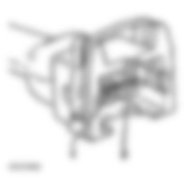
- Repair open circuit if necessary.
If no malfunctions are detected:
- Check Fuel Pump (FP) relay.
See FUEL PUMP (FP) RELAY -J17- AND RELAY ACTIVATION AND CHECKING .
Audi allroad Quattro 2005 - Checking activation
- Connect VAG 1527B voltage tester between terminal 1 (+) and 2.
- Initiate output Diagnostic Test Mode (DTM) and activate valve for camshaft adjustment.
See OUTPUT DIAGNOSTIC TEST MODE (DTM) .
- LED must blink

If LED does not blink or if it remains constantly lit:
- Connect VAG 1598/31 test box at wiring harness to ECM do not connect ECM.
- Check following wire connections for open circuit and short circuit to Ground (GND) and B+:
Valve 1 for camshaft adjustment -N205- and valve 2 for camshaft adjustment -N208-

Audi allroad Quattro 2005 SOLENOID VALVE FOR CAMSHAFT ADJUSTMENT - TERMINAL 2 CIRCUIT TEST
Harness connector terminal VAG 1598/31 or test box Bushing 2
- Repair Ground (GND) connection or open circuit if necessary.
If wire connection is OK:
- Replace Engine Control Module (ECM).
See MOTRONIC MULTIPORT FUEL INJECTION (MFI) SYSTEM, SERVICING .
If no malfunctions are detected:
- Replace mechanical camshaft adjuster.
Audi allroad Quattro 2005 - Camshafts and camshaft adjusters, removing and installing Removing
- Cylinder head installed
- Remove noise insulation panel -arrows-.
- Remove front bumper.
See FRONT BUMPER .
- Move lock carrier to service position.
- Remove ribbed belt. See RIBBED BELT, REMOVING AND INSTALLING.
- Remove toothed belt. See TOOTHED BELT, REMOVING AND INSTALLING.
Fig. 208: Audi allroad Quattro 2005 - Component Locations - Removing Noise Insulator Panel
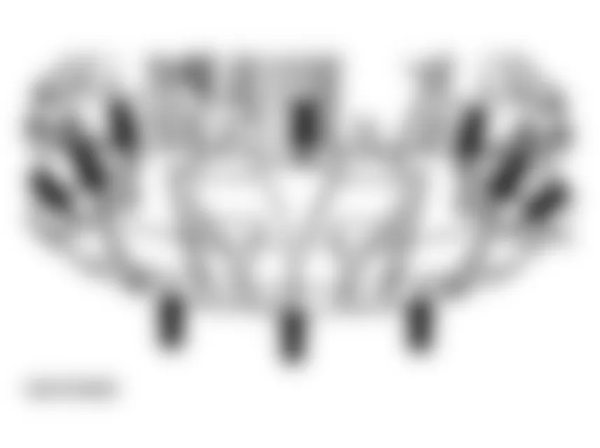
Audi allroad Quattro 2005 - Left cylinder head
- Remove left-hand cylinder head cover. See CYLINDER HEAD COVERS, REMOVING AND INSTALLING.
Audi allroad Quattro 2005 - Right cylinder head
- Remove right-hand cylinder head cover. See RIGHT CYLINDER HEAD COVER, REMOVING AND INSTALLING.
Audi allroad Quattro 2005 - All:
- Unbolt Hall sensor housing (10 Nm).
- Remove bolt securing Hall sensor rotor (20 Nm) and carefully pry off rotor using a screwdriver.
- Insert camshaft clamp 3391 in the securing plates of two camshafts.
- Loosen both camshaft bolts and remove approx. 5 turns.
- Take out camshaft clamp 3391.
- Disconnect both camshaft sprockets with special tool T40001.
- Using a screwdriver, carefully lever oil feed lines for camshaft bearings out of camshaft bearings.
Make sure that the retaining catches do not break off when prying out the oil lines.
Fig. 209: Audi allroad Quattro 2005 - Component Locations - Disconnecting Camshaft Sprockets

- Secure camshaft adjuster using retainer for chain tensioner 3366.
NOTE: Do not over-tighten retainer for chain tensioner, otherwise camshaft adjuster can be damaged.

- Check TDC position of camshafts once again.
NOTE: The two markings on the camshafts must be in line with the two arrows on the bearing caps.
- Clean drive chain and camshaft chain sprockets in vicinity of arrows on bearing caps and mark position of chain on sprockets with paint opposite two arrows.
Fig. 211: Audi allroad Quattro 2005 - Component Locations - Identifying TDC Position Of Camshafts

NOTE:

- Remove bolts securing camshaft adjuster -6-. See Fig. 213.
- Remove bearing caps 1, 3, 5 and 7 from inlet and exhaust camshafts and place them in correct order on a clean surface.
- Loosen bearing caps 2 and 4 alternately and in diagonal sequence, and remove from both camshafts.
- Take out both camshafts together with camshaft adjuster.
Fig. 213: Audi allroad Quattro 2005 - Component Locations - Removing Camshaft Adjuster And Camshafts
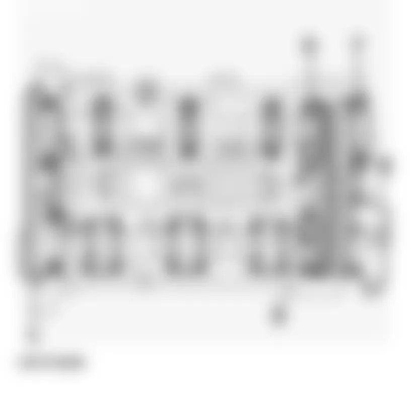
Audi allroad Quattro 2005 - Installing
- Replace rubber/metal gasket for camshaft adjuster and apply a thin coat of sealant D 454 300 A2 to shaded area.
- Install drive chain on camshaft sprockets as follows:
- When old chain is being used again, install chain so that paint markings (arrow) are in line.
- When a new chain is being installed, distance between notches -A- and -B- on camshafts must be 16 rollers on chain. Illustration shows exact positions of 1st and 16th rollers on sprockets. See Fig. 216.
- Notch -A- is offset slightly towards inside in relation to chain roller -1-.
- Insert camshaft adjuster inside chain (second mechanic required).
Fig. 216: Audi allroad Quattro 2005 - Component Locations - Installing New Camshaft Chain - Locate camshafts with chain and camshaft adjuster in cylinder head.
- Oil camshaft bearing surfaces.
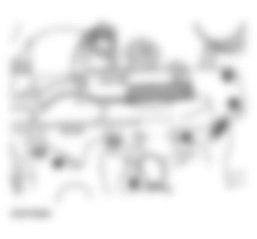
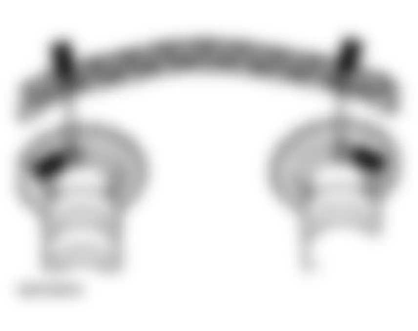
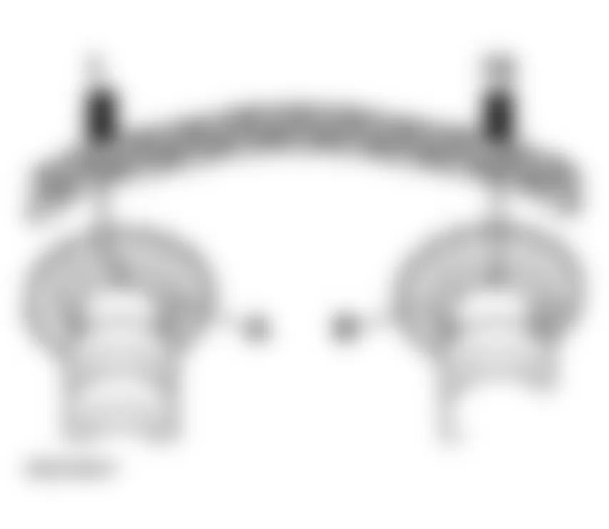
NOTE:
- Tighten bolts securing chain tensioner (watch position of dowel sleeves).
- Tighten bearing caps 2 and 4 of inlet and exhaust camshafts alternately and in diagonal sequence (watch position of dowel sleeves). See Fig. 217.
- Install two bearing caps next to chain sprockets on inlet and exhaust camshafts.
Fig. 217: Audi allroad Quattro 2005 - Component Locations - Tightening Camshaft Bearing Caps - Check correct setting of camshafts:
- Two markings on camshafts must be in line with two arrows on bearing caps -arrows-.
Fig. 218: Audi allroad Quattro 2005 - Component Locations - Identifying Markings On Camshafts - Distance between two arrows on bearing caps (or between paint markings) is 16 rollers on chain. See Fig. 219.
- Notch on exhaust camshaft is offset slightly towards inside in relation to chain roller -1-.
- Two markings on camshafts must be in line with two arrows on bearing caps -arrows-.
- Prepare shaded areas on double bearing cap -1- and bearing cap -7-.
Fig. 220: Audi allroad Quattro 2005 - Component Locations - Identifying Double Bearing Caps - ... by applying a thin coat of sealant D 454 300 A2 and install bearing caps (watch position of dowel sleeves).
- Install remaining bearing caps (watch position of dowel sleeves).
- Install new oil feed lines for camshaft bearings.
- Install new oil seals for inlet and exhaust camshafts;
- Installing, see OIL SEALS IN CYLINDER HEADS, REPLACING
- Remove retainer for chain tensioner 3366.
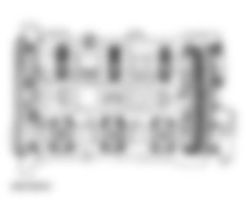

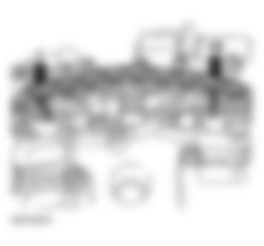
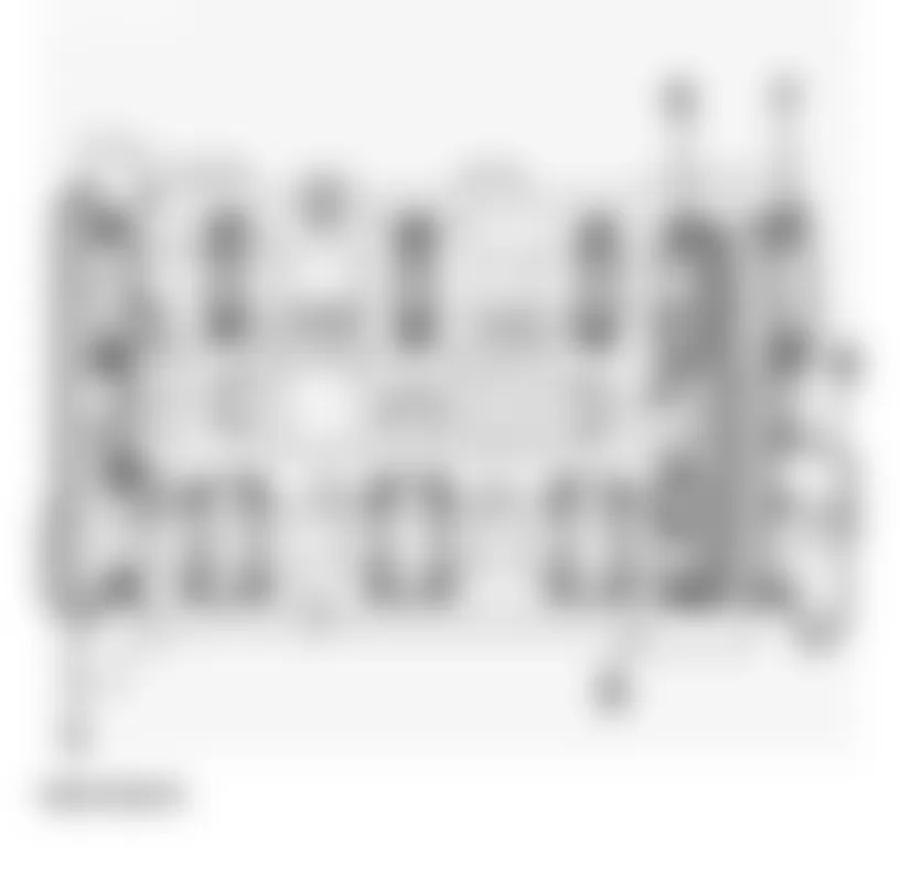

NOTE:
- Seal end points of joints between bearing caps and cylinder head.
- Before installing cylinder head cover and gasket, carefully apply a small quantity of sealant D 454 300 A2 at the four end points of sealing surfaces on cylinder head -arrows-, using a small screwdriver.
- Install cylinder head covers. See CYLINDER HEAD COVERS, REMOVING AND INSTALLING.
- Install toothed belt. See TOOTHED BELT, REMOVING AND INSTALLING.
- Install ribbed belt. See RIBBED BELT, REMOVING AND INSTALLING.

Audi allroad Quattro 2005 - Tightening torques
Audi allroad Quattro 2005 TIGHTENING TORQUES: CAMSHAFTS & CAMSHAFT ADJUSTERS
Component Nm Bolts - M6 10 Bolts - M8 20 Except for the following: Bearing caps to cylinder head 10 Camshaft adjuster to cylinder head 10 Hall sensor rotor to camshaft 25 Hall sensor housing to cylinder head 10 Camshaft sprocket to camshaft 55 Cylinder head cover 10
Audi allroad Quattro 2005 - Camshaft axial clearance, checking
- Remove camshafts. See CAMSHAFTS AND CAMSHAFT ADJUSTERS, REMOVING AND INSTALLING.
- Remove lifters.
- Install camshafts in cylinder head without drive chain and secure by tightening bearings caps 2 and 4.
- Attach dial indicator to cylinder head with universal dial indicator bracket VW 387.
- Press camshaft against dial indicator by hand.
- Set dial indicator to -0-.
- Press camshaft away from dial indicator.
- Note reading on gauge:

Audi allroad Quattro 2005 CAMSHAFT AXIAL CLEARANCE SPECIFICATIONS
New Wear limit 0.05 - 0.15 mm 0.20 mm
Audi allroad Quattro 2005 - Valve dimensions
NOTE: Valves must not be reworked. Only grinding-in (lapping) is permitted.
Fig. 224: Audi allroad Quattro 2005 - Component Locations - Identifying Valve Dimensions
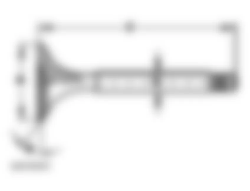
Audi allroad Quattro 2005 VALVE DIMENSIONS
Dimension Inlet valve Exhaust valve a = diameter mm 26.8 - 27.0 29.8 - 30.0 b = diameter mm 5.96 - 5.97 5.94 - 5.95 c = mm 104.84 - 105.34 103.64 - 104.14 alpha angle (degree) 45 45
WARNING: Worn sodium-cooled exhaust valves must be treated as follows before disposal: Saw the valves into two sections with a metal saw at a point between the center of the valve stem and the valve head. The valves must not come into contact with water when this is done. Then throw the valves into a bucket of water (not more than ten at a time) and step back, because a chemical reaction occurs when the sodium filling burns. After this treatment the valves can be disposed of in the normal way.
Audi allroad Quattro 2005 - Hydraulic valve lifters, checking
NOTE:
- Start engine and run until coolant temperature reaches approx. 80? C.
- Increase engine speed to about 2500 RPM for approx. 2 minutes: if necessary, perform road test.
If the hydraulic lifters are still noisy, locate malfunctioning lifters as follows:
- Remove cylinder head cover.
- Rotate crankshaft clockwise by turning securing bolt for toothed belt sprocket until cams of lifters to be checked are pointing upward.
- Measure clearance between cam and lifter.
- Push lifter down with a wooden or plastic wedge. If a 0.20 mm feeler gauge can then be inserted between camshaft and lifter, replace lifter if necessary: removing and installing camshafts and camshaft adjuster. See CAMSHAFTS AND CAMSHAFT ADJUSTERS, REMOVING AND INSTALLING.
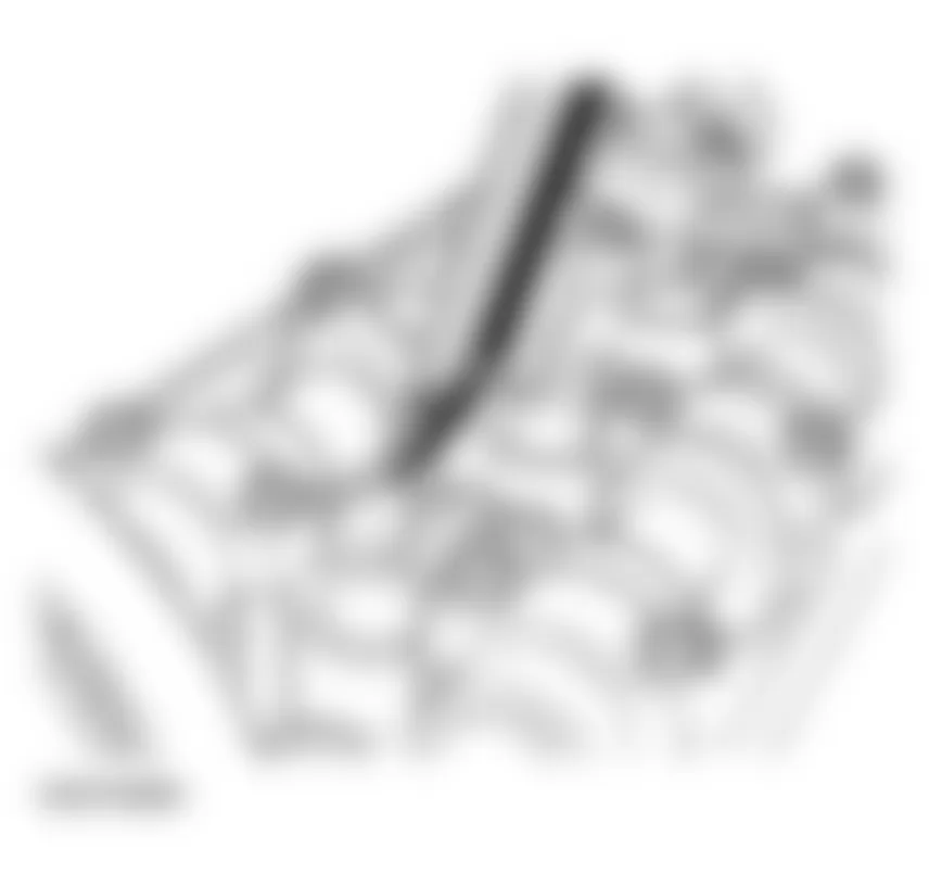
NOTE: If irregular valve noise occurs repeatedly during short journeys and disappears after extended driving, the oil check valves must be replaced. See OIL CHECK VALVES, REPLACING.
Audi allroad Quattro 2005 - Valve stem seals, replacing
- Cylinder head installed
- Remove ribbed belt. See REMOVING.
- Remove toothed belt. See TOOTHED BELT, REMOVING AND INSTALLING.
- Remove camshafts. See CAMSHAFTS AND CAMSHAFT ADJUSTERS, REMOVING AND INSTALLING.
- Remove lifters and place them down with contact surface downward. Make sure that lifters are not interchanged.
- Remove spark plugs.
- Set piston of relevant cylinder to bottom dead center.
NOTE: Tight cotters can be released by tapping lightly on the valve lever with a hammer.
Audi allroad Quattro 2005 - Exhaust side
NOTE: Before attaching the valve assembly appliance, remove the two studs in the center of the cylinder head and the three upper studs (inlet side) for securing the cylinder head cover.
- Screw pressure hose VW 653/3 with sealing ring finger-tight into spark plug thread of relevant cylinder, and maintain a constant pressure of at least 6 bar.
- Attach valve assembly appliance 2036 as illustrated: use M6 x 40 bolts with large washers. See Fig. 226.
- Remove valve spring using valve lever VW 541/1 and thrust piece VW 541/5.
- Take out valve spring and valve spring plate.
- Disconnect from valve stem seal with 3047 A.
- To prevent damage to new valve stem seals, place plastic sleeve -A- on the valve stem.
- Lightly oil sealing lip.
- Insert valve stem seal -B- (without oiling outside of seal) into installing tool 3129 and carefully push it down onto valve guide.
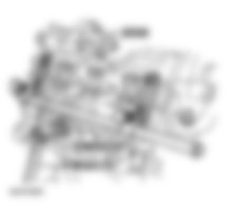
Fig. 227: Audi allroad Quattro 2005 - Component Locations - Removing Valve Stem Seals - Exhaust Side
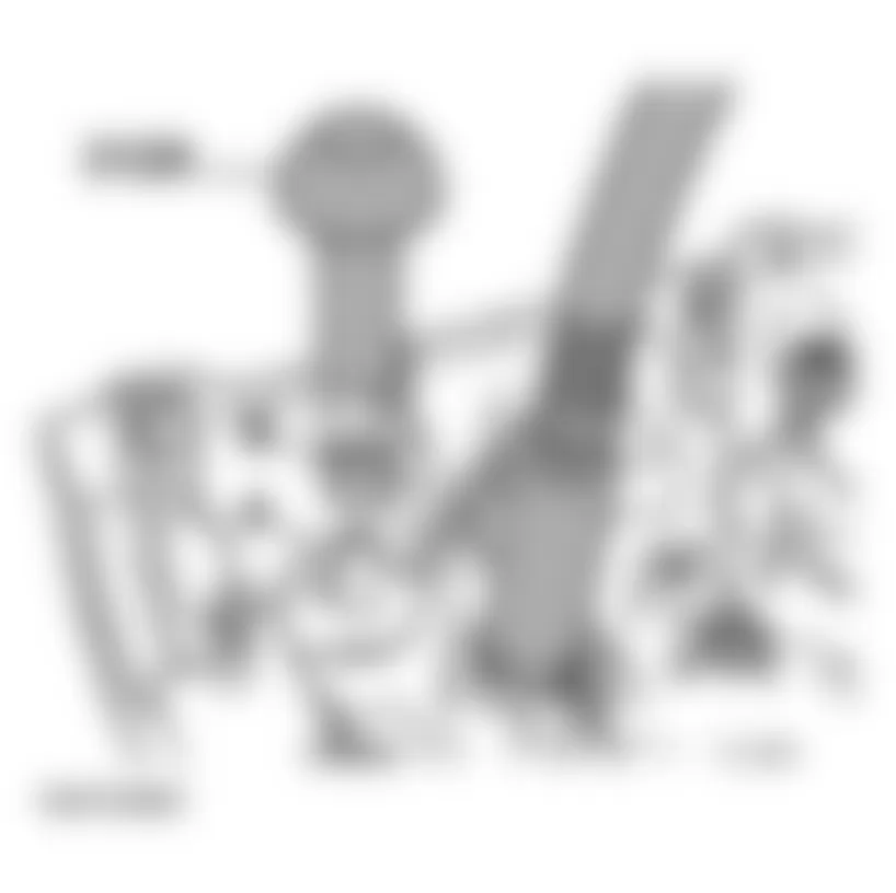
NOTE: When installing new valves, lightly oil valve stems before installing.
Audi allroad Quattro 2005 - Inlet side
NOTE: The inlet valves are installed in the cylinder head at different angles.
Valve spring compressor 3362 can be set accordingly to two different positions:
- Upper position for center valve
- Lower position for the two outer valves
- Threads on each side to take M6 x 25 bolts for securing spring compressor to cylinder head
Fig. 228: Audi allroad Quattro 2005 - Component Locations - Identifying Valve Spring Compressor
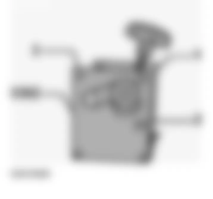
- Mount spring compressor 3362 on cylinder head with two bolts supplied, as in illustration.
- Screw pressure hose VW 653/3 with sealing ring finger-tight into spark plug thread of relevant cylinder, and maintain a constant pressure of at least 6 bar.
- Set position of spring compressor for relevant valve, and remove valve spring using threaded spindle.
- Disconnect valve stem from seal using 3364.
Fig. 230: Audi allroad Quattro 2005 - Component Locations - Disconnecting Valve Stem - Inlet Side - To prevent damage to new valve stem seals, place plastic sleeve -A- on valve stem.
- Lightly lubricate sealing lip with oil.
- Insert valve stem seal -B- (without oiling outside of seal) into installing tool 3365 and carefully push it down onto the valve guide.
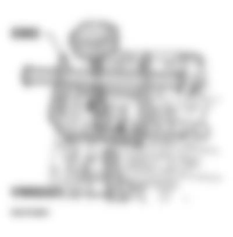
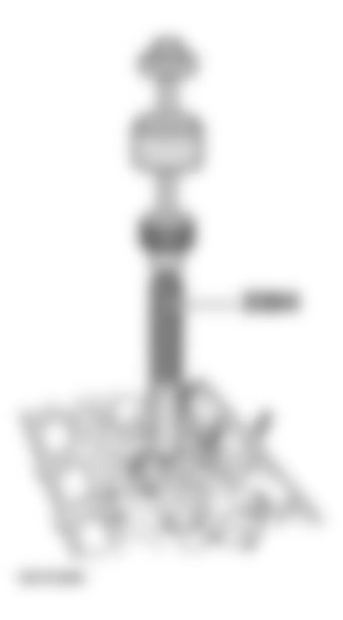
Fig. 231: Audi allroad Quattro 2005 - Component Locations - Identifying Special Service Tool

NOTE: When installing new valves, lightly oil valve stems before installing.
Audi allroad Quattro 2005 - Reworking valves
Valves must not be reworked. Only grinding-in (lapping) is permitted.
WARNING: Worn sodium-cooled exhaust valves must be treated as follows before disposal: Saw the valves into two sections with a metal saw at a point between the center of the valve stem and the valve head. The valves must not come into contact with water when this is done. Then throw the valves into a bucket of water (not more than ten at a time) and step back, because a chemical reaction occurs when the sodium filling burns. After this treatment the valves can be disposed of in the normal way.
Audi allroad Quattro 2005 - Valve guides, checking
When repairing engines or cylinder heads with leaking valves, it is not sufficient to reface the valve seats and renew the valves. The valve guides must also be checked for wear. This is particularly important on high-mileage engines.
- Insert valve into valve guide so that end of valve stem is flush with end of guide. Valve stems have different diameters, so only use an inlet valve in an inlet guide and an exhaust valve in an exhaust guide.
- Measure amount of rock.
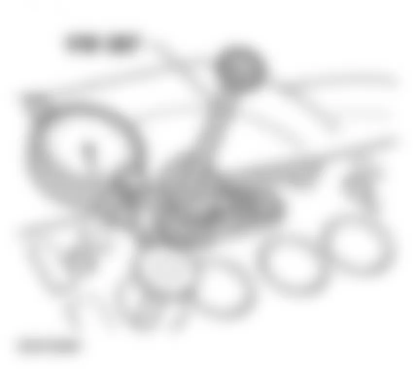
Audi allroad Quattro 2005 - Wear limit
Audi allroad Quattro 2005 VALVE GUIDE CLEARANCE (VALVE ROCK) WEAR LIMIT
Inlet valve guide Exhaust valve guide 0.8 mm 0.8 mm
If the wear limit is exceeded, replace cylinder head.
Audi allroad Quattro 2005 - Valve seats, reworking (refacing)
NOTE:
Audi allroad Quattro 2005 - Calculating maximum permissible reworking dimension
- Insert valve and press firmly against valve seat.
NOTE: If the valve is to be replaced as part of a repair, use a new valve for the calculation.
- Measure distance between end of valve stem and top surface of cylinder head (illustration shows a 4-valve head).
- Calculate maximum permissible reworking dimension from measured distance and minimum dimension.
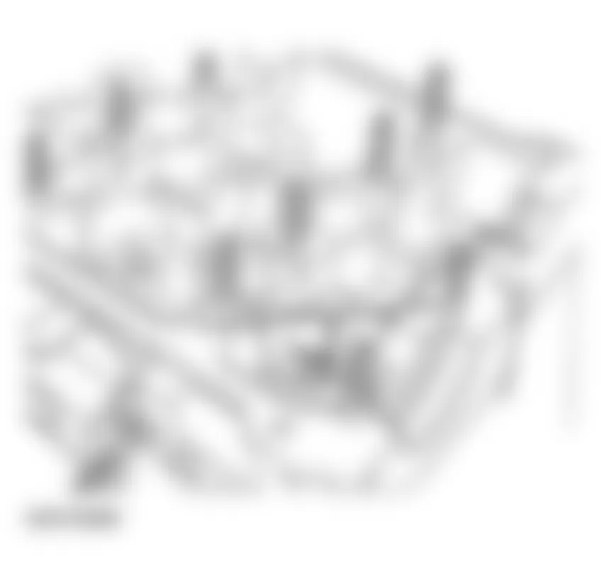
Audi allroad Quattro 2005 CALCULATE MAXIMUM PERMISSIBLE VALVE SEAT REWORKING DIMENSION
Minimum dimensions Outer inlet valve Center inlet valve Exhaust valve 32.2 mm 33.2 mm 33.0 mm
Measured distance minus minimum dimension = maximum permissible reworking dimension.
Audi allroad Quattro 2005 CALCULATE MAXIMUM PERMISSIBLE VALVE SEAT REWORKING DIMENSION (EXAMPLE)
Center inlet valve Dimension Measured distance 33.0 mm Minimum dimension -32.2 mm Maximum permissible reworking dimension = 0.8 mm
NOTE: If the measured distance is less than the minimum dimension, repeat the measurement with new valves, or replace cylinder head.
Audi allroad Quattro 2005 - Engine - Lubrication Lubrication system components, removing and installing
CAUTION: Before beginning repairs on the electrical system:
NOTE:
Viscosity grades, Oil capacities and oil specifications, see ENGINE OIL, FILLING
Checking oil pressure, see OIL PRESSURE AND OIL PRESSURE SWITCH, CHECKING
Audi allroad Quattro 2005 - Crankcase breather and oil spray jets
Removing and installing oil pump, oil pan, oil filter and oil cooler: See UPPER AND LOWER SECTIONS OF OIL PAN, REMOVING AND INSTALLING.Fig. 234
NOTE: The following list refers to items in .
- - Bolt, tightening torque: 20 Nm
- - Washer
- - Tensioning roller
- - Bolt, tightening torque: 45 Nm
- - Idler wheel
- For toothed belt
- - Bolt
- M6 Tightening torque: 10 Nm
- M8 Tightening torque: 20 Nm
- - Bolt, tightening torque 10 Nm
- - Breather housing
- - Gasket/breather plate
- Always replace
- - Oil check valve
- Tightening torque: 25 Nm
- - Oil seal
- - Connector
- - Banjo bolt
- Tightening torque: 15 Nm
- - Oil distribution line
- For oil spray jets for piston cooling
- - Cylinder block
- - Bolt, tightening torque 10 Nm
- Apply locking fluid "D6" when installing
- - Oil spray jet
- For piston cooling
- - Gasket
- Metal gasket
- Always replace
- - Engine Oil Temperature Sensor-G8-, tightening torque 10 Nm
- For oil temperature gauge
- White
- If seal is leaking, cut open with pliers and replace.
- - Oil seal
- Replacing, see OIL SEALS IN CYLINDER HEADS, REPLACING
- - Tensioner
- Secure in position before removing. See SECURING TENSIONER IN POSITION BEFORE REMOVING.
- - Bolt, tightening torque: 10 Nm
- Apply locking fluid "D6" when installing
- - Washer
- - Bearing bushing
- For tensioning lever
- - Washer
- - Bolt, tightening torque: 25 Nm
- - Tensioning lever
- - Bearing bushing
- For tensioning roller
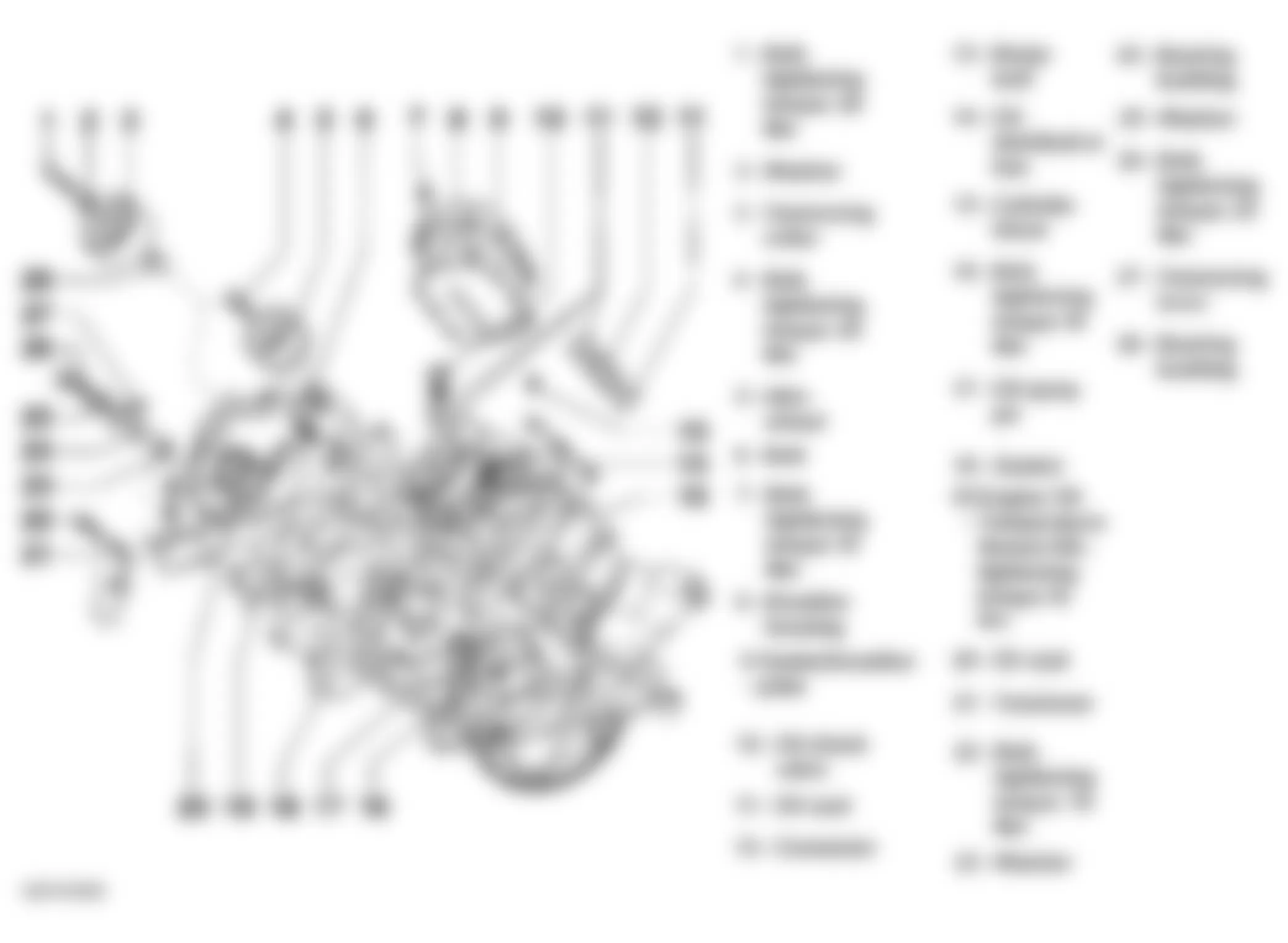
Audi allroad Quattro 2005 - Securing tensioner in position before removing
- Using a hex key, turn toothed belt tensioning roller -1- clockwise 8 mm in direction of arrow until tensioning lever -2-compresses tensioner -3- far enough to enable a 2 mm dia. spring pin to be inserted in drilling and in plunger.
NOTE: - The toothed belt tensioner is oil-damped and can only be compressed slowly by applying gradual pressure.
- Use spring pin from 2024 A.
Fig. 235: Audi allroad Quattro 2005 - Component Locations - Turning Toothed (Timing) Belt Tensioner - Insert spring pin and release toothed belt tensioning roller.
Audi allroad Quattro 2005 - Oil pump, oil pan, oil filter and oil cooler, removing and installing
NOTE: The following list refers to items in Fig. 236.
- - Bolt for dipstick guide tube
- Tightening torque: 25 Nm
- - Dipstick guide tube
- Replace O-ring
- - Oil pan - upper section
- There is no gasket between engine block and upper section of oil pan. Only use silicone sealant D 454 300 A2.
- - Hex socket head bolt M8
- Tightening torque: 20 Nm
- - Hex bolt M6
- Tightening torque: 15 Nm
- - Hex socket head bolt M8
- Tightening torque: 20 Nm
- The coolant drain screw is next to this bolt
- - Hex bolt M6
- Tightening torque: 10 Nm
- - O-ring
- Always replace
- - Gasket for lower section of oil pan
- Sealing surfaces should be clean and dry
- - Oil drain plug
- Tightening torque: 30 Nm
- - Seal for oil drain plug
- Oil pan
- - Hex bolt M6
- Tightening torque: 10 Nm
- - Oil pan -lower section
- - Hex bolt M6
- Tightening torque: 10 Nm
- - Retainer for oil lines
- - Oil supply line
- From pump to oil filter
- - Oil supply line
- From oil filter to engine oil system
- - O-ring
- Always replace
- - O-ring
- Always replace
- - Oil filter
- - Hex nut
- Tightening torque: 30 Nm
- Threaded line for oil cooler and oil filter is screwed into upper section of oil pan with 20 Nm tightening torque.
- - Oil cooler
- Make sure O-ring is installed correctly when installing
- - Oil pump
- Driven off crankshaft via chain
- Tightening torque of chain sprocket to oil pump: 25 Nm
- Tightening torque of oil pump to engine block: 25 Nm
Fig. 236: Audi allroad Quattro 2005 - Component Locations - Exploded View Of Oil Pans And Oil Cooler
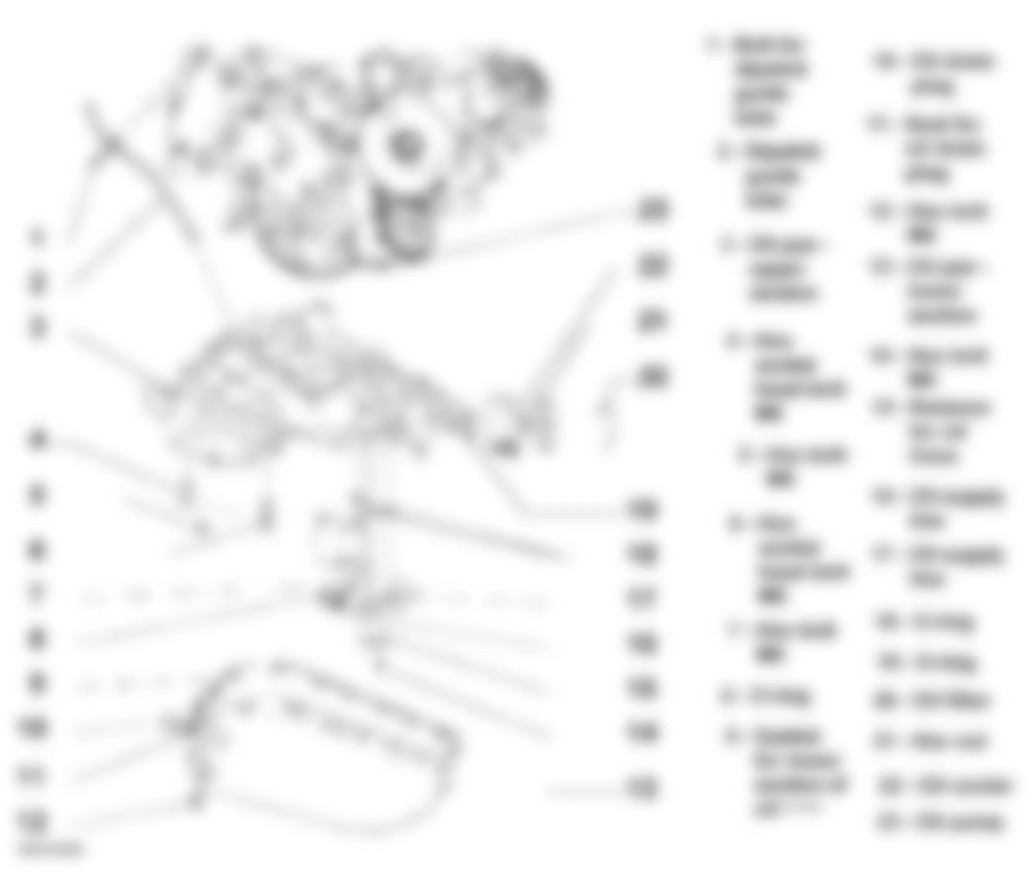
Audi allroad Quattro 2005 - Oil check valves, replacing
NOTE: If irregular valve noise occurs repeatedly during short journeys and disappears after extended driving, the oil check valves must be replaced.
- All cable ties which are released or cut open when removing the engine must be replaced in the same position when installing the engine.
- Catch drained-off coolant in a clean container for re-use or disposal.
- Replace all gaskets and seals.
Audi allroad Quattro 2005 - Removing
- Remove bolts -arrows- and remove engine cover panels C-.
- Remove cover above air cleaner.
Fig. 237: Audi allroad Quattro 2005 - Component Locations - Removing Engine Cover Panels - Remove noise insulation -arrows-.
- Drain coolant. See COOLING SYSTEM, DRAINING AND FILLING .
- Remove bumper.
See FRONT BUMPER .
- Move lock carrier to service position.
See LOCK CARRIER, SERVICE POSITION .
Fig. 238: Audi allroad Quattro 2005 - Component Locations - Removing Noise Insulation - Remove viscous fan (counter-hold with pin wrench 3212).
NOTE: Viscous fan has LEFT-HAND thread. - Mark direction of rotation of ribbed belt.
- Loosen ribbed belt by turning to right using a 17 mm box wrench until two holes are aligned with each other -arrow- and hold in position with mandrel 3204.
NOTE: Mark direction of rotation of ribbed belt. The belt can break if it runs in the opposite direction when reinstalled. - Remove ribbed belt.
- Disconnect water hoses -1- and -2-.
- Remove coolant reservoir (arrows).
- Disconnect connector for coolant level monitor.
- Remove cover panel from cylinder head cover (cylinder bank 4 through 6).
- Disconnect hose -1- from vacuum reservoir.
Fig. 242: Audi allroad Quattro 2005 - Component Locations - Disconnecting Vacuum Reservoir - Remove air duct -arrows-.
Fig. 243: Audi allroad Quattro 2005 - Component Locations - Removing Air DuctWARNING: Fuel system is under pressure. Before opening the system, place a cloth around the connection. Then release pressure by carefully loosening the connection. - Disconnect fuel supply line and fuel return line -1- and -2-, and move fuel lines clear. See Fig. 244.
- Disconnect hose from EVAP valve -3-.
- Install clamp (special tool 3094) on hose from power steering reservoir to power steering pump.
- Disconnect power steering hose -arrow-.
Fig. 245: Audi allroad Quattro 2005 - Component Locations - Disconnecting Power Steering Hose - Release hose clamp -arrow-.
- Remove intake line -1-.
Fig. 246: Audi allroad Quattro 2005 - Component Locations - Removing Hose Clamp And Intake LineNOTE: - All hose connections are secured with clips.
- Charge air system must be free of leaks.
- Replace all seals and gaskets.
- Disconnect connector from air recirculation valve -2-.
- Disconnect connector from camshaft timing control -1- (cylinder bank 4 through 6).
- Disconnect connectors from injectors -2- (cylinder bank 4 through 6).
- Disconnect crankcase breather -4- from cylinder head cover (cylinder bank 4 through 6).
- Disconnect connectors from injectors -2- (cylinder bank 1 through 3).
- Disconnect hose -5- going from turbocharger intake side. See Fig. 249.
- Unclip solenoid valve for charge air pressure control -1-.
- Disconnect connector from EVAP valve -2-.
- Disconnect connector from throttle unit -1-. See Fig. 251.
- Disconnect connector from charge air pressure sensor -2-.
- Disconnect crankcase breather -3-.
- Disconnect connector from intake air temperature sensor -4-.
Fig. 251: Audi allroad Quattro 2005 - Component Locations - Disconnecting Connectors On Engine - Remove pressure lines -1-.
NOTE: Observe position of retaining strips -2-.
Fig. 252: Audi allroad Quattro 2005 - Component Locations - Removing Pressure Lines - Remove tensioner -1- for ribbed belt.
- Remove toothed belt guards -2- (left and right).
- Remove toothed belt guard -3- (center).
- Turn crankshaft to TDC by hand. Marks -A- and -B- must be alignened.
NOTE: Turn over the engine at the central bolt on the crankshaft. - Check position of camshafts: larger holes in securing plates on camshaft sprockets must align opposite one another on inside. If not, turn crankshaft one revolution further.
- Remove sealing plug from cylinder block, left.
TDC drilling in crankshaft must be visible (or able to be felt) in line with sealing plug hole.
- Screw clamping bolt 3242 for crankshaft into sealing plug hole and tighten.
NOTE: - Mark the direction of rotation of the toothed belt with chalk or felt pen before removing. A used belt can break if it rotates in the wrong direction when reinstalled.
- The toothed belt tensioning element is oil-damped and can therefore only be compressed slowly by applying constant pressure.
- Using a hex key, turn toothed belt tensioning roller -1- clockwise 8 mm in direction of arrow until tensioning lever 2- compresses tensioning element -3- sufficiently to enable special tool T 400 11 to be installed in drilling and in plunger.
- Insert special tool T 400 11 and release toothed belt tensioning roller.
- Insert camshaft clamp 3391 in securing plates of two camshafts.
- Loosen both camshaft bolts and remove approx. 5 turns.
- Remove camshaft clamp 3391.
- Disconnect both camshaft sprockets with special tool T40001.
Fig. 257: Audi allroad Quattro 2005 - Component Locations - Disconnecting Camshaft Sprockets - Unbolt rear left toothed belt guard -arrows-.
- Detach intake manifold using special tool 3249.
Fig. 258: Audi allroad Quattro 2005 - Component Locations - Removing Rear Left Toothed Belt Guard - Unbolt cylinder head lifting bracket with coolant line -arrows- from cylinder head.
- Unbolt coolant line at front of cylinder head -arrows- and remove.
- Remove water line and auxiliary water pump.
- Remove cover on oil check valves.
- Replace oil check valves -1- (25 Nm).
NOTE: The oil distribution line -2- for the spray jets for piston cooling is also located in the opening.


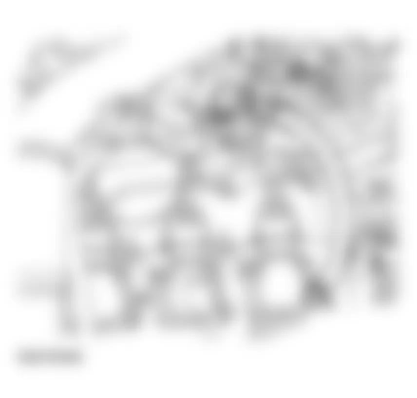


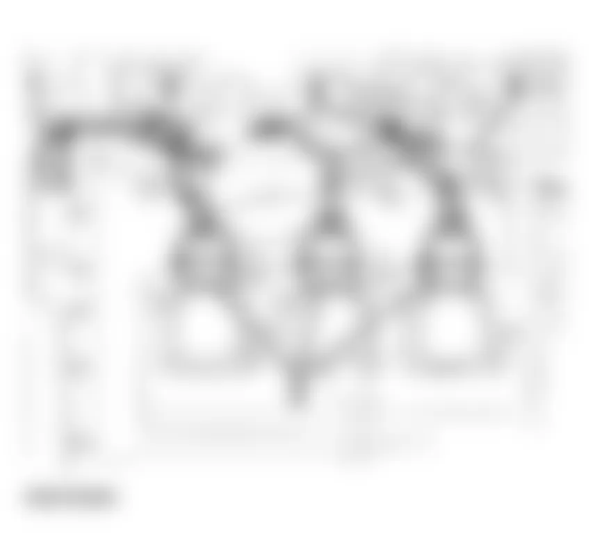
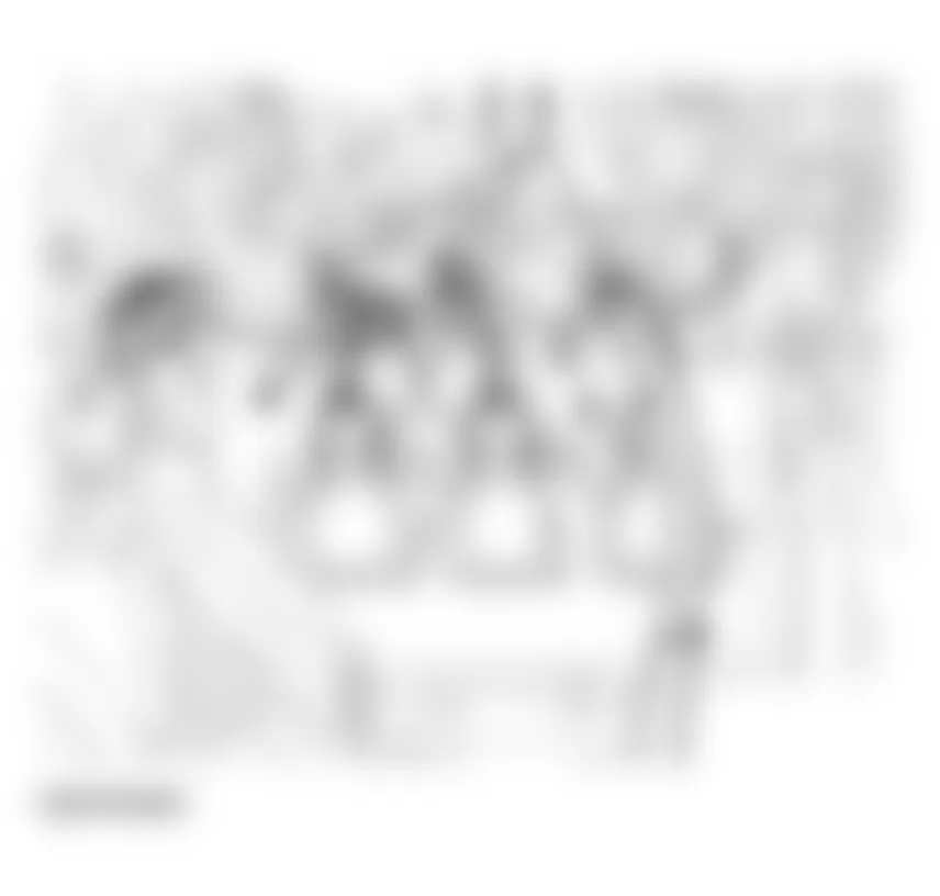
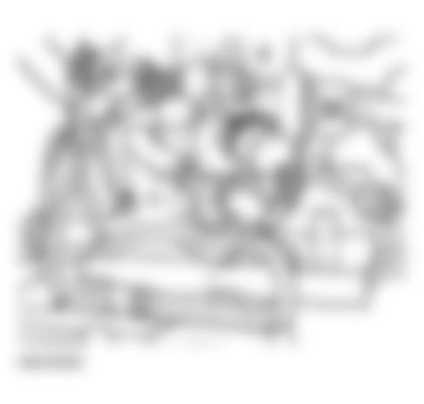


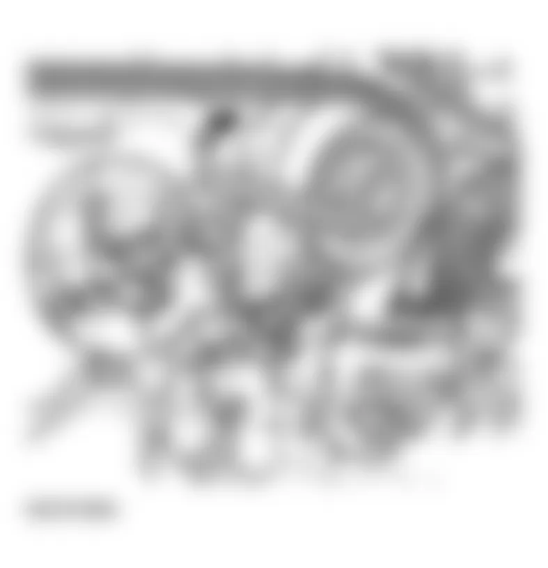


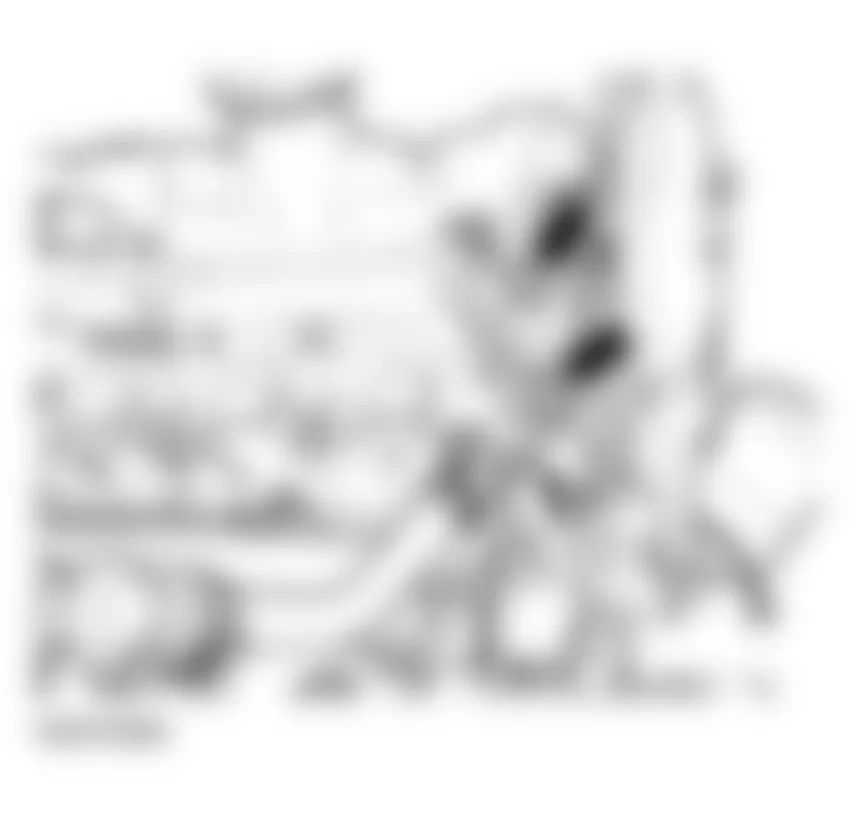
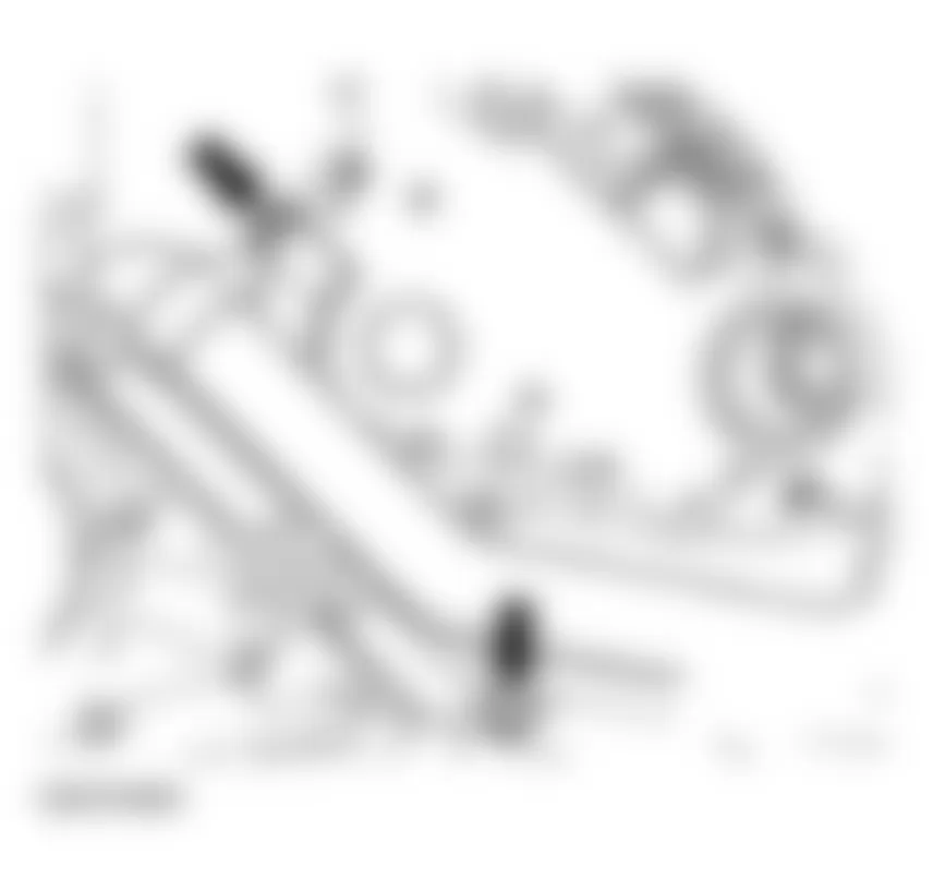
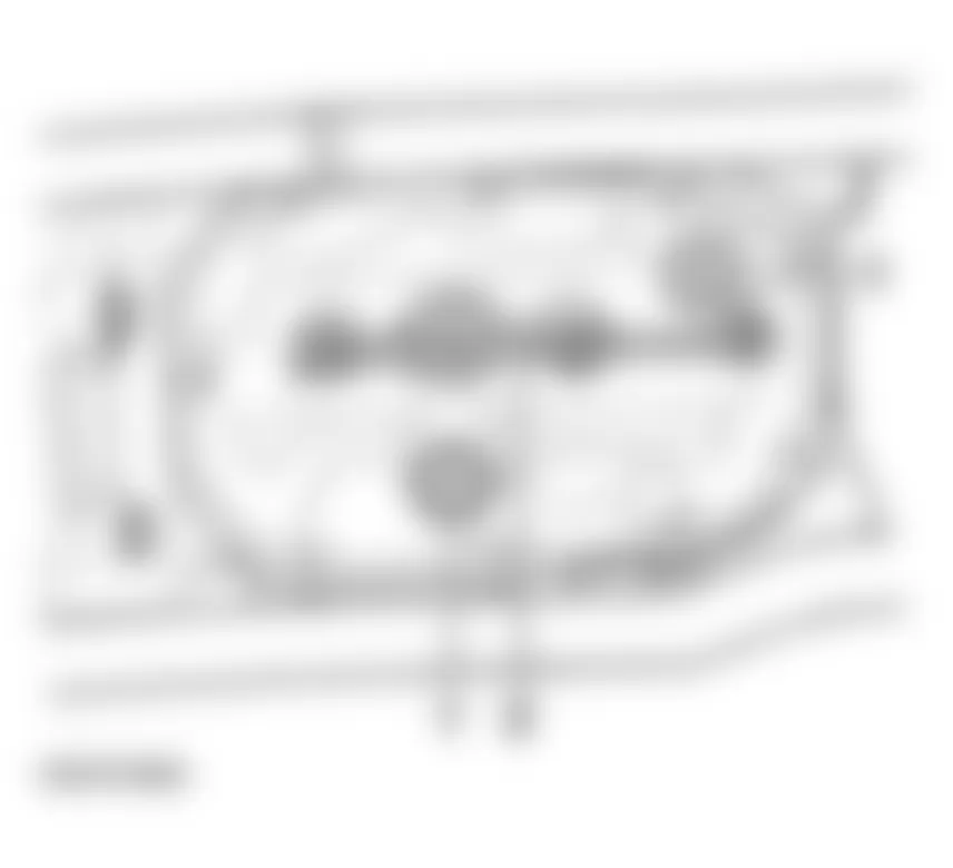
Audi allroad Quattro 2005 - Installing
Install in the opposite order to removing. When installing, note the following points:
- Install lock carrier.
- Install bumper.
See FRONT BUMPER .
- Fill with coolant. See COOLING SYSTEM, DRAINING AND FILLING .
Audi allroad Quattro 2005 TIGHTENING TORQUES: OIL CHECK VALVES
Component Nm Bolts - M6 10 Bolts - M8 20 Toothed belt sprocket to camshaft 55 Intake manifold to cylinder head 10 Oil check valves 25 Cover for oil check valves 10
Audi allroad Quattro 2005 - Lower section of oil pan, removing and installing Special tools, testers and auxiliary items
- Drip tray VAG 1306
Audi allroad Quattro 2005 - Removing
- Remove noise insulation panel -arrows-.
- Remove bumper.
See FRONT BUMPER .
- Move lock carrier to service position.
- Remove ribbed belt. See RIBBED BELT, REMOVING AND INSTALLING.
Fig. 262: Audi allroad Quattro 2005 - Component Locations - Removing Noise Insulation Panel - Unbolt air conditioner lines from oil pan -arrow-.
WARNING: Do not open air conditioner refrigerant circuit. - Detach air conditioner compressor lines -1- and -2-.
NOTE: - Watch position of guide bushings when installing.
- When installing, insert bolt -1- in the compressor first.
- To prevent damage to the condenser and refrigerant lines/hoses, ensure that the lines and hoses are not stretched, kinked or bent.
- Drain engine oil.
NOTE: Use a separate container to collect the engine oil. - Remove lower section of oil pan.
Fig. 265: Audi allroad Quattro 2005 - Component Locations - Removing Lower Section Of Oil Pan

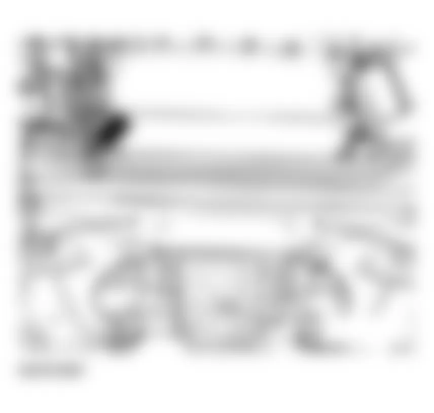
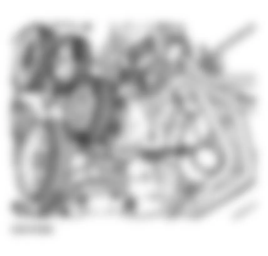

Audi allroad Quattro 2005 - Installing
Install in the opposite order to removing. When installing, note the following points:
NOTE: Do not use any adhesive or sealant.
- Clean sealing surfaces; make sure that they are free of oil and grease.
- Install new gasket on lower section of oil pan and install on upper section of oil pan with two diagonally opposite bolts.
- Tighten all securing bolts hand-tight.
- Tighten bolts to 10 Nm with torque wrench, working from center outward.
- Install new seal on oil drain plug and tighten to 30 Nm.
- Fill engine with oil.
Oil capacities, ENGINE OIL, FILLING
- Install lock carrier in normal position.
- Install bumper.
See FRONT BUMPER .
Audi allroad Quattro 2005 - Chain tensioner for oil pump, checking Removing
The chain tensioner incorporates a leaf spring. To check the spring tension, the lower section of the oil pan must be removed.
- Remove bumper.
See FRONT BUMPER .
- Move lock carrier to service position.
- Remove ribbed belt. See RIBBED BELT, REMOVING AND INSTALLING.
- Remove lower section of oil pan. See LOWER SECTION OF OIL PAN, REMOVING AND INSTALLING.
- Insert a screwdriver between chain and chain tensioner and press screwdriver against chain tensioner.
If no spring tension can be felt and the chain is not being tensioned, this means the chain tensioner is malfunctioning and must be replaced.
Fig. 266: Audi allroad Quattro 2005 - Component Locations - Pressing Chain TensionerTo replace oil pump chain tensioner, remove front sealing flange. See FRONT SEALING FLANGE AND OIL PUMP DRIVE CHAIN, REMOVING AND INSTALLING.
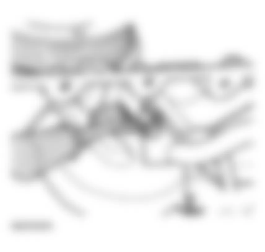
Audi allroad Quattro 2005 - Installing
Install in the opposite order to removing. When installing, note the following points:
- Fill engine with oil.
Oil capacities, see ENGINE OIL, FILLING
- Install lock carrier in normal position.
- Install bumper.
See FRONT BUMPER .
Audi allroad Quattro 2005 - Upper and lower sections of oil pan, removing and installing Special tools and equipment
- Engine support bracket 10-222A with adapter 10-222A/3
- Drip tray VAG 1306
- Electric drill with plastic brush attachment
- Silicone sealant D 176 404 A2
- Torque wrench 10 Nm/ 45 Nm
Audi allroad Quattro 2005 - Removing
See Caution before beginning repairs on the electrical system under LUBRICATION SYSTEM COMPONENTS, REMOVING AND INSTALLING.
- With ignition switched off, disconnect battery Ground strap.
- Pull out dipstick.
- Unbolt dipstick guide tube at front of cylinder head (right side), and pull out of oil pan from the top.
- Remove noise insulation panel -arrows-.
Fig. 267: Audi allroad Quattro 2005 - Component Locations - Removing Noise Insulation Panel - Remove bumper.
See FRONT BUMPER .
- Move lock carrier to service position.
See LOCK CARRIER, SERVICE POSITION .
WARNING: Hot steam can escape from the expansion tank when the filler cap is opened. Cover the filler cap with a cloth and remove it carefully. - Remove cap on coolant expansion tank.
- Place drip tray VAG 1306 below engine.
- Turn drain screw -arrow- on radiator counter-clockwise, if necessary install drain hose to connection.
Fig. 268: Audi allroad Quattro 2005 - Component Locations - Locating Drain Screw On Radiator - Also open coolant drain screw -arrow- at rear right of oil pan. See COOLING SYSTEM, DRAINING AND FILLING .
- Drain engine oil.
Use a separate container to collect the engine oil.
- Set up support bracket 10-222A with adapter 10-222A/3 on bolted flanges for wing panels.
- Attach support bracket to front and rear lifting eyes on engine.
- Raise engine as far as possible with spindles of support bracket.
- Cut open cable ties -arrows-, open retainer for starter cable and take out cable.
Fig. 271: Audi allroad Quattro 2005 - Component Locations - Disconnecting Open Cable Ties - Unbolt torque reaction support at front of oil pan.
- Unbolt coolant line from oil pan.
- Disconnect connector from oil pressure switch on left of oil pan.
- Remove torque reaction support -1-.
- Release hose clamps -arrows-.
- Remove water line -2-.
- Place drip tray VAG 1306 under engine.
- Remove oil filter.
- Release hose clamps -arrows-. See Fig. 273.
- Remove oil cooler -1-.
Fig. 273: Audi allroad Quattro 2005 - Component Locations - Removing Oil Cooler - Remove lower nuts on engine mountings -1- (left and right sides).
- Mark positions of securing points -1- and locating sleeves -2- under engine mountings on left and right sides.
Fig. 274: Audi allroad Quattro 2005 - Component Locations - Removing Lower Nuts On Engine Mountings - Remove front subframe bolts -2- and -3-(left and right).
- Remove bolts -4-.
- Move stabilizer bar downward.
- Remove charge air cooler -2- on right side (release hose connection at top, and 3 rubber mountings).
Fig. 275: Audi allroad Quattro 2005 - Component Locations - Removing Front Subframe Bolts - Remove air duct from connector elbow on alternator -3-.
- Disconnect cable from terminal 30/B+ -1-. Tightening torque: 16 Nm. See Fig. 276.
- Disconnect cable from terminal D+ -2-. Tightening torque: 4 Nm
- Remove hex socket head bolt -1- and securing nut -2-. Tightening torque: 45 Nm
- Loosen bolt -3-. Tightening torque 22 Nm
- Remove alternator -4- from below.
Fig. 277: Audi allroad Quattro 2005 - Component Locations - Removing Hex Socket Head From Alternator
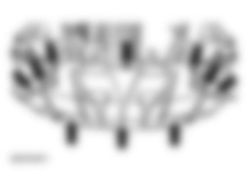
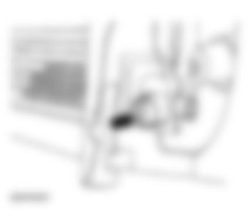
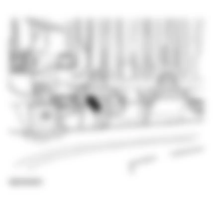
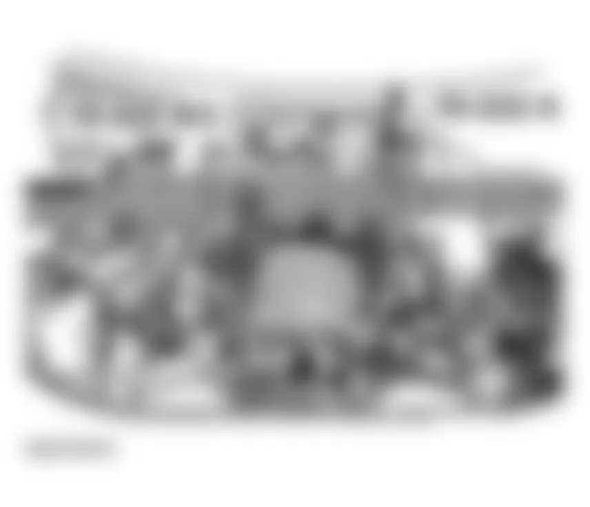
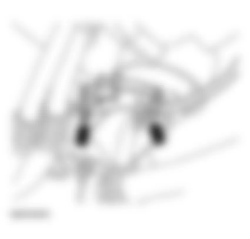
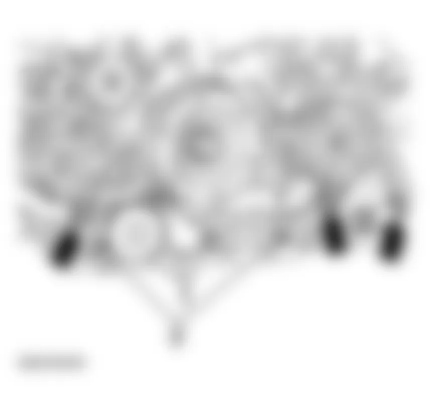

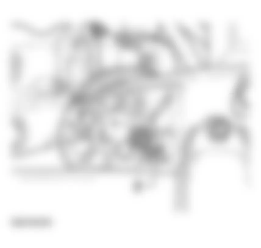
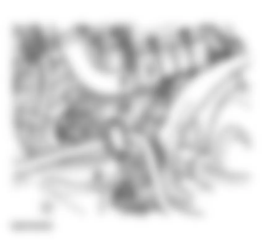

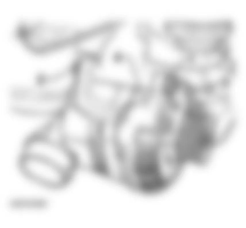
- Remove air line -1-.
Fig. 278: Audi allroad Quattro 2005 - Component Locations - Removing Air Line - Mounting for oil line and air conditioner lines
- Mounting on cylinder block
- Release hose clamp

- Disconnect cable from terminal 30/B+ -1-. Tightening torque: 16 Nm
- Disconnect connector for terminal 50 -2-.
- Remove right wheel.
- Remove top bolt -1- from right wheelhousing. Tightening torque: 65 Nm
- Remove lower bolt (accessible from engine side). Tightening torque: 65 Nm
- Remove starter from front of vehicle.
NOTE: To avoid having to check and adjust wheel alignment, only loosen the front subframe mountings and lower the subframe at the front. - Remove lower section of oil pan.
- Disconnect return lines for turbocharger from upper section of oil pan.
Fig. 281: Audi allroad Quattro 2005 - Component Locations - Removing Lower Section Of Oil Pan - Unbolt cover plate -2- for oil pump sprocket.
NOTE: - When loosening bolt -2- securing cover plate, counter-hold at welded nut.
- When installing, make sure that the plate engages in position -arrows-.
- Unbolt two oil supply lines, and pull longer of two lines downward to disconnect from upper section of oil pan.
Fig. 283: Audi allroad Quattro 2005 - Component Locations - Locating Oil Supply Lines - Unbolt oil pump from engine so that shorter oil supply line can be disconnected (do not remove oil pump).
- Remove bolts securing upper section of oil pan to transmission.
- Unbolt upper section of oil pan from engine.
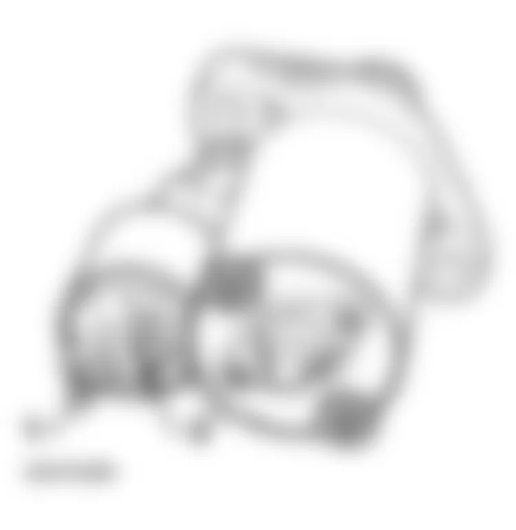


NOTE: Two M6 bolts and two M8 bolts are located vertically at rear of oil pan upper section (in front of joint between engine and transmission).
Audi allroad Quattro 2005 - Installing:
See Caution for connecting Telematics battery under LUBRICATION SYSTEM COMPONENTS, REMOVING AND INSTALLING.
Install in the opposite order to removing. When installing, note the following points:
- Clean sealing surfaces; ensure that they are free of oil grease.
WARNING: Wear protective goggles. - Remove any residues of sealant on oil pan and engine block using plastic brush attachment, or similar.
NOTE: The oil pan must be installed within 5 minutes after applying silicone sealant D 454 300 A2.
Fig. 285: Audi allroad Quattro 2005 - Component Locations - Removing Sealant On Oil Pan - Cut off nozzle of tube at front marking (diameter of nozzle approx. 3 mm).
- Thickness of sealant bead: 2 - 3 mm
Fig. 286: Audi allroad Quattro 2005 - Component Locations - Cutting Off Nozzle TubeNOTE: The bead of sealant must not be thicker than 3 mm, as otherwise excess sealant may enter the oil pan and block the strainer in the oil intake line. - Make sure sealing surface is clean and then apply silicone sealant on sealing surface of oil pan, as shown in illustration. (Illustration shows position of sealant on cylinder block.)
NOTE: Be particularly careful when applying the sealant around the rear sealing flange -arrows in illustration-. - Locate oil pan in position immediately, and tighten all bolts securing pan to cylinder block to 5 Nm initially.
- Tighten bolts securing oil pan to transmission to 45 Nm.
- Tighten bolts securing oil pan to cylinder block in diagonal sequence in 2 stages; tighten to 10 Nm when tightening second time.
- Tighten M10 bolts securing oil pan to cylinder block to 45 Nm.
Fig. 287: Audi allroad Quattro 2005 - Component Locations - Applying Silicone Sealant - Clean both sealing surfaces for lower section of oil pan; make sure that they are free of oil and grease.
NOTE: Do not use any adhesive or sealant. - Install new gasket on lower section of oil pan and install on upper section of pan with two diagonally opposite bolts.
- Tighten all securing bolts hand-tight.
- Tighten bolts to 10 Nm with torque wrench, working from center outward.
- Install new seal on oil drain plug and tighten to 30 Nm.
NOTE: - When installing the upper section of the oil pan with the engine removed from the vehicle, make sure that the pan is positioned flush with the cylinder block at the flywheel end.
- The sealant must be left to dry for about 30 minutes after installing the oil pan before the engine can be filled with oil.
- Fill with coolant. See COOLING SYSTEM, DRAINING AND FILLING .
- Fill engine with oil.
Oil capacities, see ENGINE OIL, FILLING
- Install subframe.
- Install lock carrier in normal position.
- Install bumper.
See FRONT BUMPER .
- Install noise insulation.
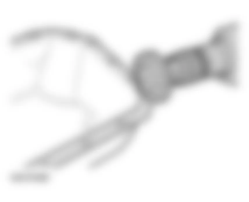
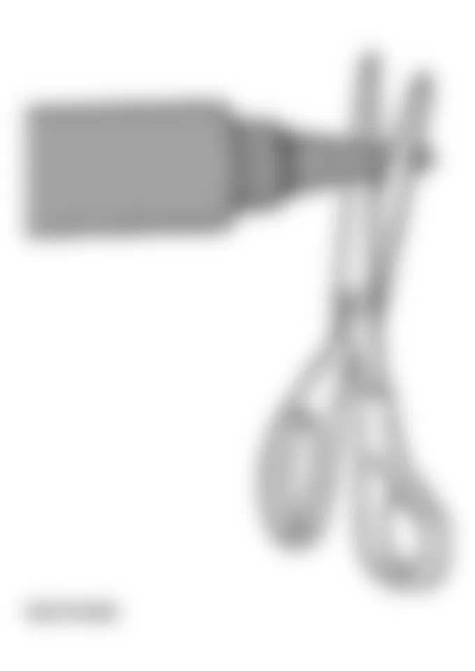
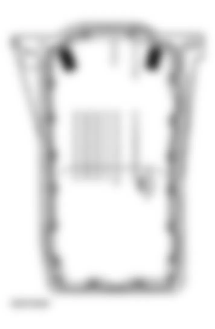
Audi allroad Quattro 2005 - Tightening torques
Audi allroad Quattro 2005 TIGHTENING TORQUES: UPPER AND LOWER SECTIONS OF OIL PAN
Component Nm Upper section of oil pan to cylinder block - M6 10 Upper section of oil pan to cylinder block - M8 20 Lower section of oil pan to upper section of oil pan 10 Oil pan to transmission - M8 25 Oil pan to transmission-M10 45 Coolant line to oil pan 10 Oil drain plug in lower section of oil pan 30 Dipstick guide tube to cylinder head 25 Oil pump to cylinder block 25 Oil pump supply lines to upper section of oil pan 10 Front sealing flange-M6 10 Collar bolt-M8 30 Bracket for coolant lines to oil pan 10 Coolant drain screw on engine 20 Stop for torque reaction support to bracket on engine 25 Engine mounting to subframe 25 Torque reaction support to front of oil pan 25 Engine mounting to engine support 25 Chain sprocket to oil pump 25
WARNING: Combi bolt -4- MUST BE REPLACED after removing. See Fig. 288.
Fig. 288: Audi allroad Quattro 2005 - Component Locations - Identifying Subframe Mounting Bolts

Audi allroad Quattro 2005 - Oil pump, removing and installing Removing
- Remove noise insulation panel -arrows-.
- Remove bumper.
See FRONT BUMPER .
- Move lock carrier to service position.
See LOCK CARRIER, SERVICE POSITION .
Fig. 289: Audi allroad Quattro 2005 - Component Locations - Removing Noise Insulation Panel - Unbolt air conditioner lines from oil pan -arrows-.
WARNING: Do not open air conditioner refrigerant circuit. - Detach air conditioner compressor -1- and -3-.
NOTE: - Watch position of guide bushings when installing.
- When installing, insert bolt -1- in the compressor first.
- To prevent damage to the condenser and refrigerant lines/hoses, make sure that the lines and hoses are not stretched, kinked or bent.
- Drain engine oil.
Fig. 291: Audi allroad Quattro 2005 - Component Locations - Removing Air Conditioner CompressorNOTE: Use a separate container to collect the engine oil. - Remove lower section of oil pan.
Fig. 292: Audi allroad Quattro 2005 - Component Locations - Removing Lower Section Of Oil Pan - Unbolt cover plate -2- for oil pump sprocket.
NOTE: - When loosening bolt -2- securing cover plate, counter-hold at welded nut.
- When installing, make sure that the plate engages in position -arrows-.
- Unbolt brackets for oil supply lines -arrows- and pull front (longer) oil supply line away downward.
Fig. 294: Audi allroad Quattro 2005 - Component Locations - Removing Brackets For Oil Supply Lines - Remove bolt securing chain sprocket to oil pump using Torx T45, and pull sprocket off oil pump.
- Remove oil pump together with shorter oil supply line.

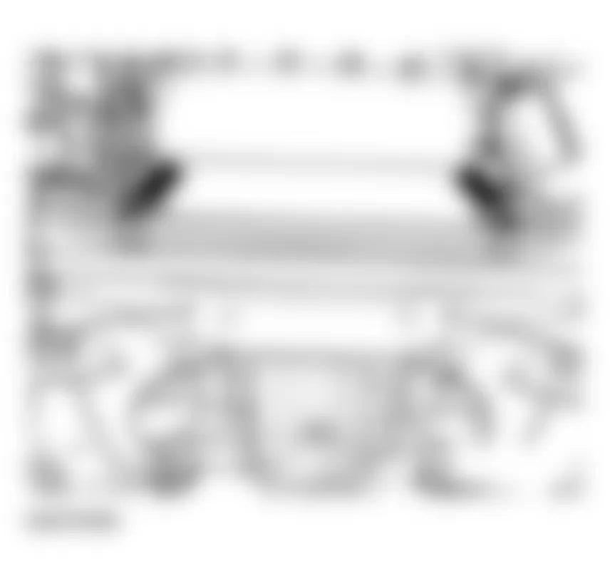
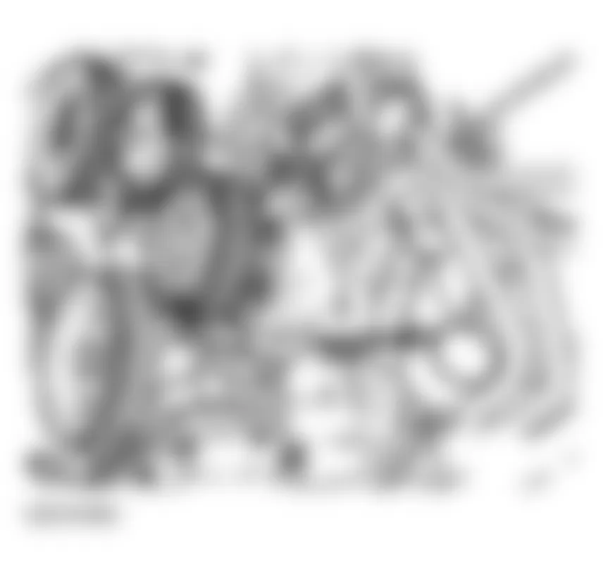
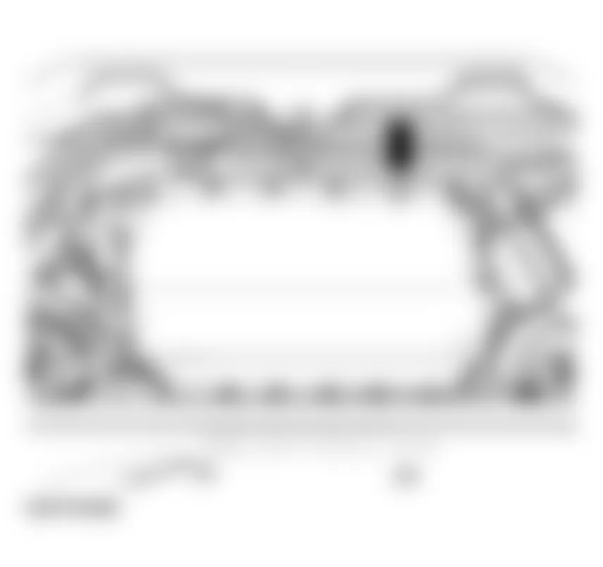


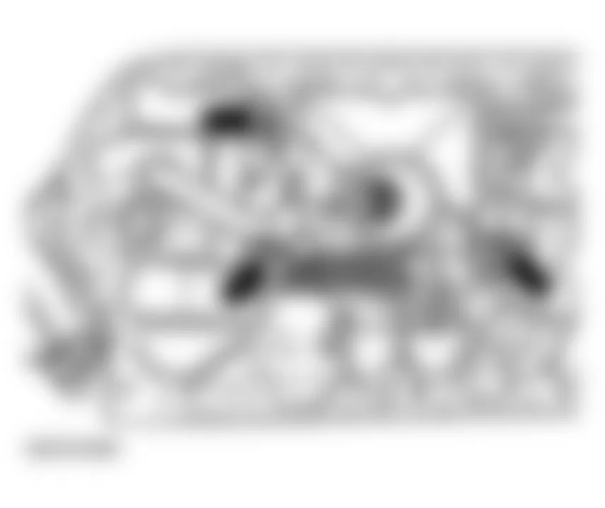
Audi allroad Quattro 2005 - Installing
Install in the opposite order to removing. When installing, note the following points:
- Before bolting on oil pump, install short oil supply line into pump and upper section of oil pan with new O-rings.
- Bolt on cover plate -2- for oil pump sprocket.
NOTE: - When installing, make sure that the plate engages in position -arrows-.
- When tightening bolt -2- securing cover plate, counter-hold at welded nut.
Fig. 297: Audi allroad Quattro 2005 - Component Locations - Tightening Cover Plate Bolts - Clean both sealing surfaces for lower section of oil pan; make sure that they are free of oil and grease.
NOTE: Do not use any adhesive or sealant. - Install new gasket on lower section of oil pan and install on upper section of oil pan with two diagonally opposite bolts.
- Tighten all securing bolts hand-tight.
- Tighten bolts to 10 Nm with torque wrench, working from center outward.
- Install new seal on oil drain plug and tighten to 30 Nm.
- Fill engine with oil.
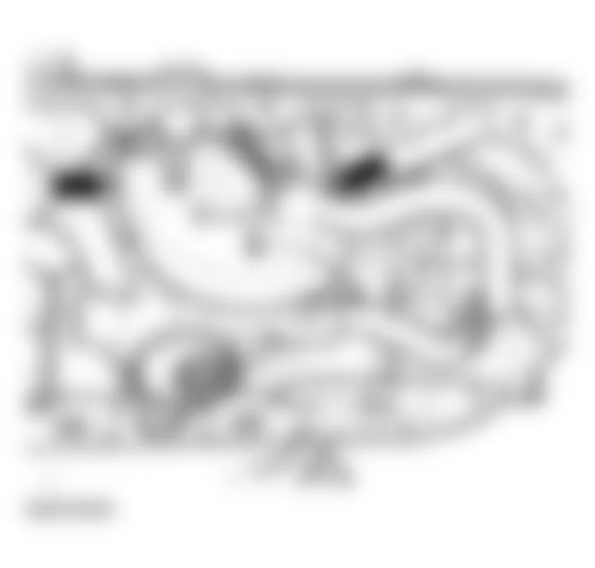
Oil capacities, see ENGINE OIL, FILLING
- Install subframe.
- Install lock carrier in normal position.
- Install bumper.
See FRONT BUMPER .
Audi allroad Quattro 2005 - Tightening torques
Audi allroad Quattro 2005 TIGHTENING TORQUES: OIL PUMP
Component Nm Chain sprocket to oil pan 25 Lower section of oil pan to upper section of oil pan 10 Oil drain plug in lower section of oil pan 30 Oil pump to cylinder block 25 A/C compressor to bracket 25 Oil pump supply lines to upper section of oil pan 10 racket for A/C lines to oil pan 10
Audi allroad Quattro 2005 - Front sealing flange and oil pump drive chain, removing and installing Removing
- Remove ribbed belt. See RIBBED BELT, REMOVING AND INSTALLING
- Remove toothed belt. See TOOTHED BELT, REMOVING AND INSTALLING.
- Drain engine oil.
NOTE: Use a separate container to collect the engine oil. - Remove lower section of oil pan.
- Unbolt cover plate for oil pump sprocket (-2-).
NOTE: - When loosening bolt -2- securing cover plate, counter-hold at welded nut.
- When installing, make sure that the plate engages in position -arrows-.
Fig. 298: Audi allroad Quattro 2005 - Component Locations - Removing Lower Section Of Oil Pan - Unbolt both oil supply lines -1- and -3- from upper section of oil pan and pull longer of two lines away downward.
Fig. 299: Audi allroad Quattro 2005 - Component Locations - Removing Oil Supply Lines - Remove 4 bolts from upper section of oil pan.
- Remove following components before unbolting front sealing flange:
- Tensioning roller for toothed belt: 20 Nm
- Idler wheel: 45 Nm
- Toothed belt tensioner: 10 Nm
- Lever for toothed belt tensioner: 20 Nm
- Unbolt front sealing flange and take off gasket for front sealing flange M6 bolts: 10 Nm M8 collar bolt: 30 Nm.
Fig. 302: Audi allroad Quattro 2005 - Component Locations - Removing Front Sealing Flange

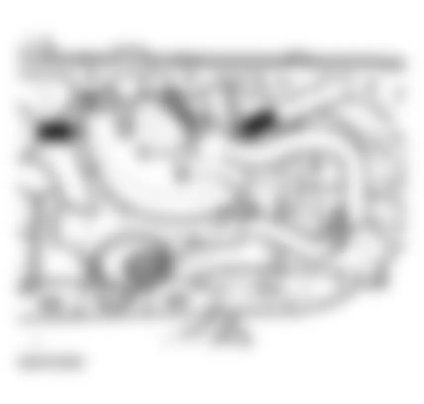
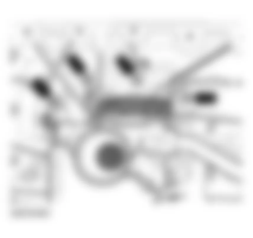
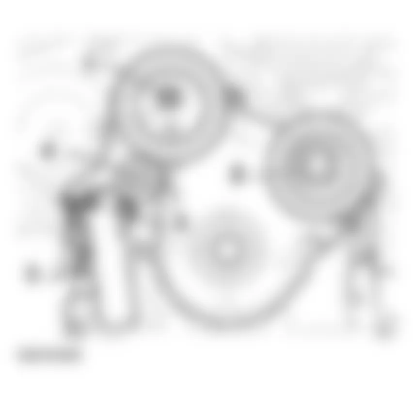
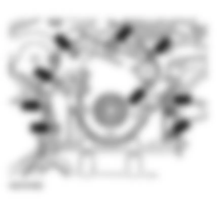
Audi allroad Quattro 2005 - Replacing oil pump drive chain
- Remove bolt securing chain sprocket to oil pump using Torx T45, and pull sprocket off oil pump.
Fig. 303: Audi allroad Quattro 2005 - Component Locations - Removing Oil Pump Chain Sprocket - Remove oil pump together with shorter oil supply line.
Fig. 304: Audi allroad Quattro 2005 - Component Locations - Removing Oil Pump And Oil Supply Line - Take out oil pump sprocket and remove drive chain from crankshaft.

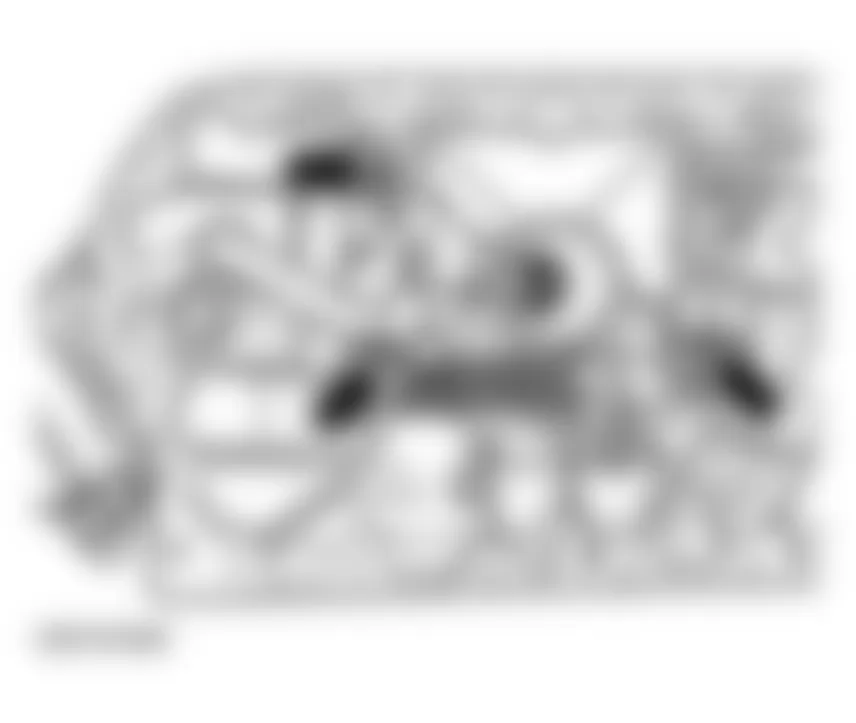
Removing and installing chain sprocket on crankshaft , see CHAIN SPROCKET FOR OIL PUMP ON CRANKSHAFT, REMOVING AND INSTALLING
Audi allroad Quattro 2005 - Installing
Install in the opposite order to removing. When installing, note the following points:
- Remove any residues of sealant on front of oil pan or engine block, if necessary.
- Clean sealing surfaces; ensure that they are free of oil and grease.
NOTE: The front sealing flange must be installed within 5 minutes of applying silicone sealant D 454 300 A2. NOTE: Do not apply any sealant on sealing surface -A- of the cylinder block. - After installing gasket on sealing surface -A-, apply a small quantity of sealant to joints between two arrows -left and right-. See Fig. 305.
Fig. 305: Audi allroad Quattro 2005 - Component Locations - Locating Gasket Sealing Surface -A- - Cut off nozzle of tube at front marking (diameter of nozzle approx. 3 mm).
- Thickness of sealant bead: 2 to 3 mm
NOTE: The bead of sealant must not be thicker than 3 mm, as otherwise excess sealant may enter the oil pan and block the strainer in the oil intake line.
Fig. 306: Audi allroad Quattro 2005 - Component Locations - Installing Oil Intake Line - Make sure sealing surface is clean and then apply silicone sealant on sealing surfaceof front sealing flange, as shown in illustration. (The illustration shows where the bead of sealant is applied)
- Use installing sleeve 3202/1 to install sealing flange. Locate sealing flange in position immediately and tighten all 4 bolts in oil pan hand-tight initially.
- Tighten bolts securing sealing flange Tightening torque: Front sealing flange: M6 10 Nm, M8 20 Nm 4 bolts in oil pan: 10 Nm
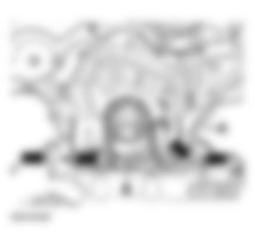


Audi allroad Quattro 2005 - Chain sprocket for oil pump on crankshaft, removing and installing Removing
Removing and installing front sealing flange and oil pump drive chain. See FRONT SEALING FLANGE AND OIL PUMP DRIVE CHAIN, REMOVING AND INSTALLING.
- Pull chain sprocket off crankshaft using a normal commercial-type puller -2-: use a suitable washer -1- to protect end of crankshaft.
Audi allroad Quattro 2005 - Installing
- Heat chain sprocket in oven for about 15 minutes at 220;deg;C.
Fig. 308: Audi allroad Quattro 2005 - Component Locations - Removing Chain Sprocket From CrankshaftNOTE: - Wear protective gloves.
- Installation position: it must be possible to read the lettering on the chain sprocket.
- Using pliers, install chain sprocket on end of crankshaft and push against stop on crankshaft with drift sleeve 30-100. If necessary knock on carefully using a plastic hammer.
Removing and installing front sealing flange and oil pump drive chain. See FRONT SEALING FLANGE AND OIL PUMP DRIVE CHAIN, REMOVING AND INSTALLING.
Fig. 309: Audi allroad Quattro 2005 - Component Locations - Installing Chain Sprocket On Crankshaft
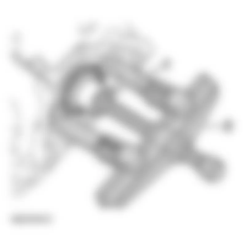
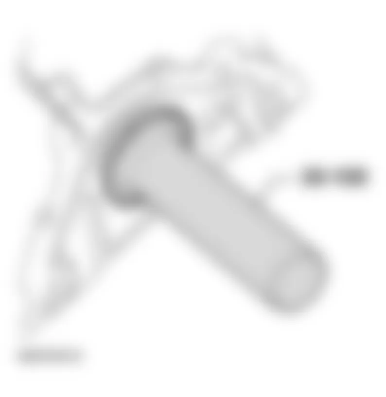
Audi allroad Quattro 2005 - Crankshaft oil seal - pulley end, replacing Removing
- Remove bumper.
See FRONT BUMPER .
- Move lock carrier to service position.
- Remove ribbed belt. See RIBBED BELT, REMOVING AND INSTALLING.
- Remove toothed belt. See TOOTHED BELT, REMOVING AND INSTALLING.
- Remove sealing plug from hole in cylinder block (left side).
- Position crankshaft to TDC of No. 3 cylinder.
TDC drilling should be visible (or it should be possible to feel the drilling) in the sealing plug hole.
- Screw clamping bolt 3242 into hole so that crankshaft is secured against turning.
Fig. 310: Audi allroad Quattro 2005 - Component Locations - Installing Clamping Bolt 3242 - Remove crankshaft toothed belt sprocket.
- Remove inner part of oil seal extractor 3203 two turns (approx. 3 mm) out of outer part and lock with knurled screw.
- Lubricate threaded head of oil seal extractor, place it in position and, exerting firm pressure, screw it in as far as possible into oil seal.
- Loosen knurled screw and turn inner part against crankshaft until oil seal is pulled out.

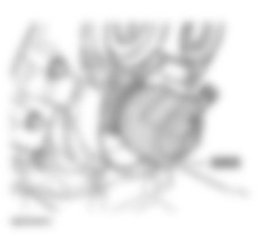
Audi allroad Quattro 2005 - Installing
- Place guide sleeve 3202/1 onto crankshaft journal.
- Slide dry seal over guide sleeve.
- Press oil seal in flush with installing sleeve 3265.
Then proceed as for removing, performing steps in reverse order.

Audi allroad Quattro 2005 - Oil pressure and oil pressure switch, checking Test procedure
- Remove oil pressure switch-F1- and screw oil pressure switch into tester.
- Screw tester into oil pan in place of oil pressure switch.
- Connect brown wire of tester to Ground (-).
- Using test leads from VAG 1594, connect diode test lamp VAG 1527 between positive battery terminal (+) and oil pressure switch.
- Start engine and gradually increase engine speed. LED should light up at 1.2 -1.6 bar, otherwise replace oil pressure switch.
- Increase engine speed further. At 2000 RPM and an oil temperature of 80;deg; C oil pressure should be at least 2.0 bar.
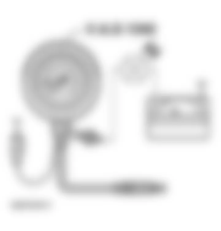
Audi allroad Quattro 2005 - Engine oil
A high-quality multigrade oil is put in at the factory: this can be used all year round, except in extremely cold climates.
Audi allroad Quattro 2005 - Viscosity grades and oil specifications
Viscosity grades and oil specifications, see ENGINE OIL, FILLING
Audi allroad Quattro 2005 - Oil level, checking Test conditions
- Oil temperature above 60;deg; C.
- Vehicle level.
- Wait for a few minutes after switching off the engine to allow the oil to flow back into the oil pan.
Audi allroad Quattro 2005 - Test sequence
- Remove dipstick, wipe off with a clean cloth and insert it again as far as it will go.
- Remove dipstick again and read oil level.
Markings on oil dipstick:
- Do not top off oil.
- Oil can be topped off. The oil level may rise as far as area -a- after topping off.
- Oil must be topped off. It is sufficient if the oil level is somewhere in area -b-(grooved area on dipstick) after topping off.
NOTE: The oil level must not be above marking -a-on the dipstick. Oil capacities, see ENGINE OIL, FILLING
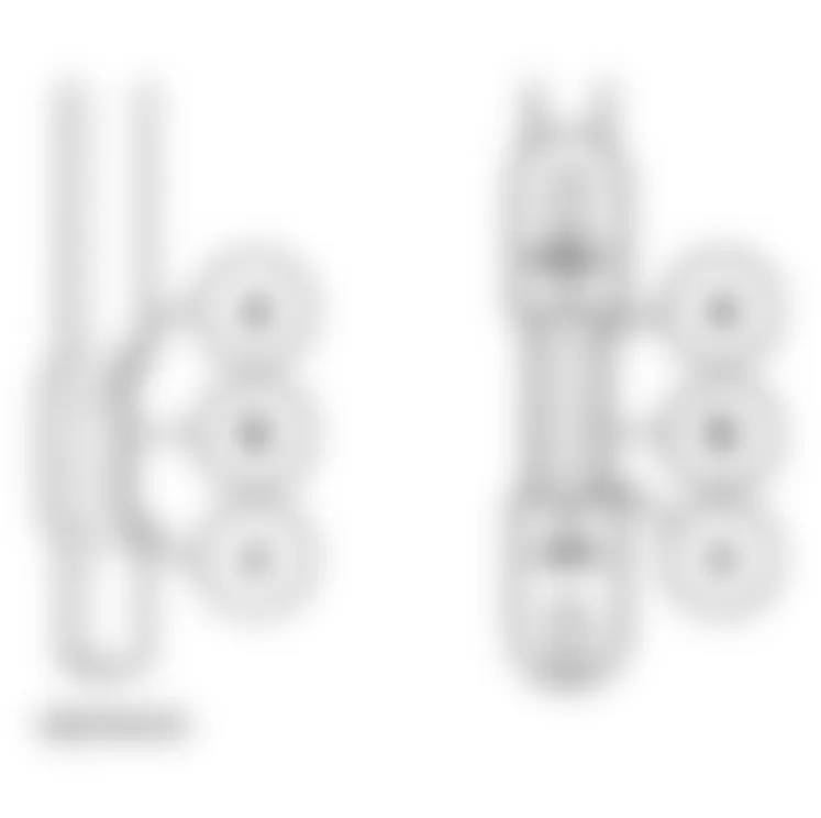