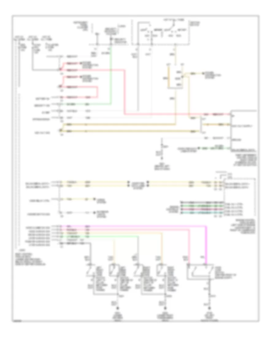
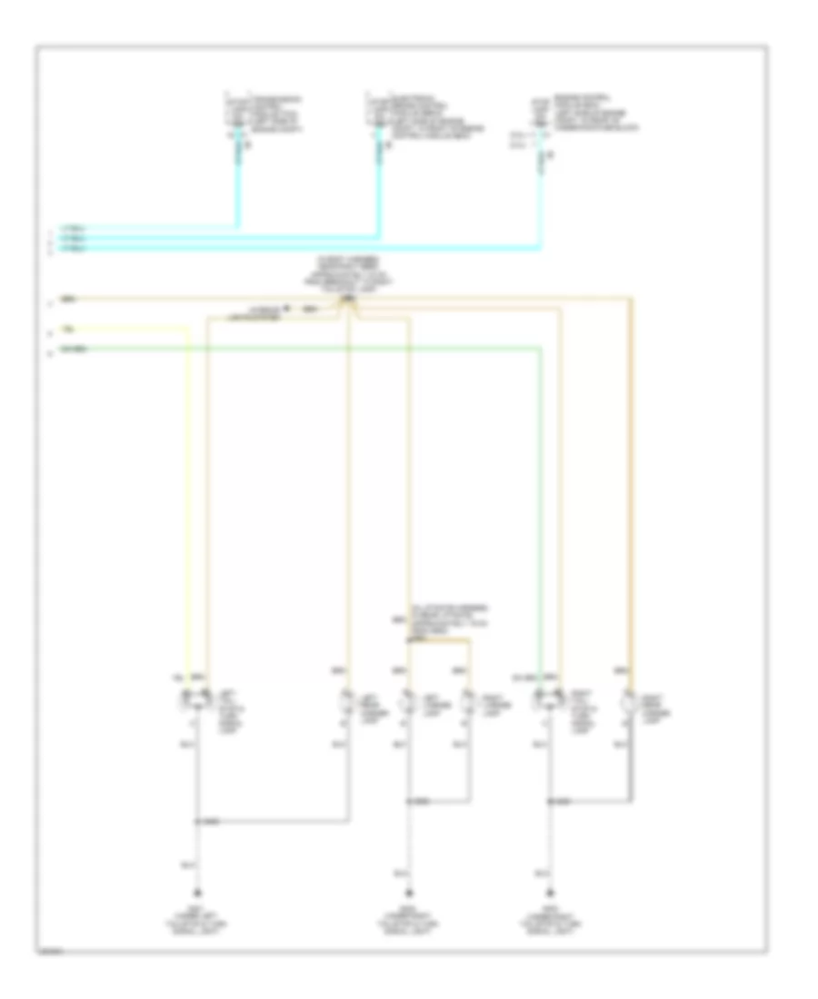
AIR CONDITIONING
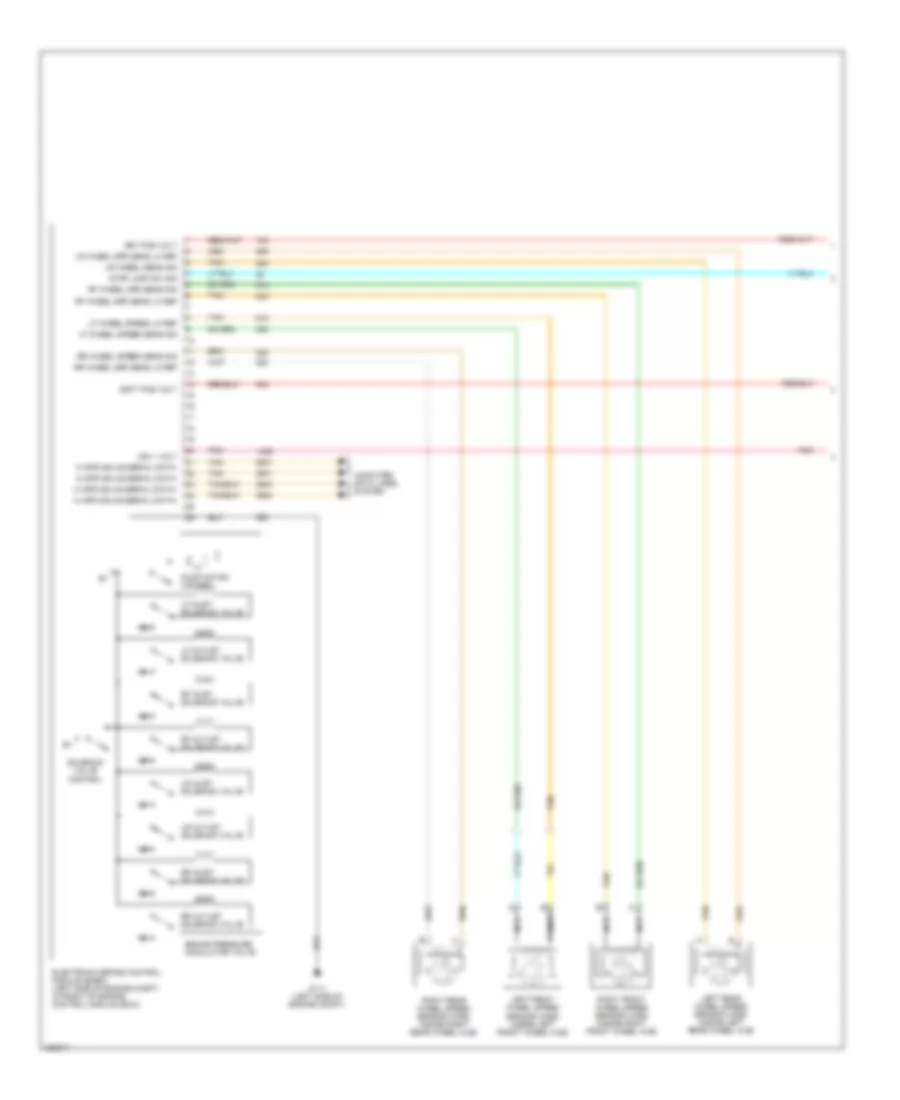
Compressor Wiring Diagram for Chevrolet HHR LS 2006
 https://portal-diagnostov.com/license.html
Automotive Electricians Portal FZCO
Automotive Electricians Portal FZCO
https://portal-diagnostov.com/license.html
https://portal-diagnostov.com/license.html
Automotive Electricians Portal FZCO
Automotive Electricians Portal FZCO
List of elements for Compressor Wiring Diagram for Chevrolet HHR LS 2006:
- (2.4l: right side of engine, near exhaust manifold) (2.2l:top right rear of engine) engine coolant temperature (ect) sensor
- (not used)
- 2.2l
- 2.4l
- 5v ref
- A/c clutch relay
- A/c compressor clutch (lower left front of engine)
- A/c compressor clutch diode
- A/c refrigerant pressure sensor (in right front of engine compt, on a/c line, near compressor)
- A/c req sig
- A/c request indicator
- A/c request sig
- A/c request switch
- Batt
- Body control module (bcm) (under center dash, below radio, on right side of center console)
- C1 d3
- C3 c5
- Computer data lines system
- D12 c1
- Ect sig
- Engine control module (ecm) (left side of engine compt, in front of underhood fuse block)
- F10
- F11 c2
- G109 (on left front shock tower)
- G203 (behind left end of dash)
- Gnd
- Hot at all times
- Hot in run or start
- Hot w/ run/ crank relay energized
- Hvac control assembly
- Hvac/ i/p ign fuse 10a
- Hvac/pk3 fuse 10a
- Ign 1 voltage
- Logic
- Low ref
- Pnk
- Power distribution system
- Press sens sig
- Rly ctrl
- S101 (in forward lamp harness, near left front headlamp, approximately 9 cm from breakout to g109)
- S200 (in i/p harness, near left side of i/p, approximately 29 cm from breakout to g203)
- Serial data
- Serial data +
- Serial data -
- Tan
- Underhood fuse block (in engine compt, next to left strut tower)
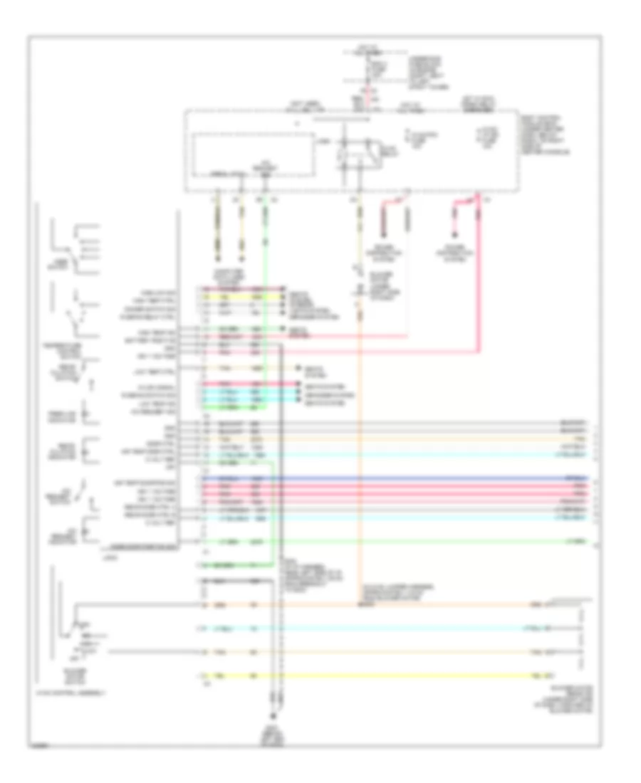
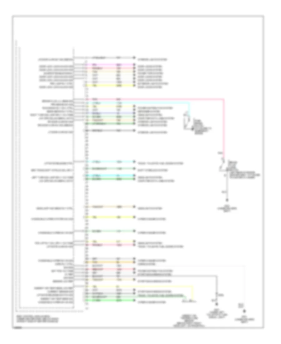
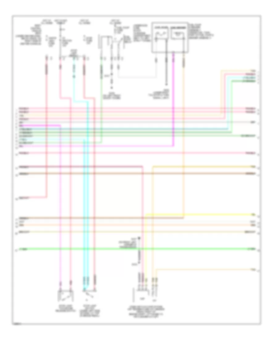
Manual A/C Wiring Diagram (1 of 2) for Chevrolet HHR LS 2006
 https://portal-diagnostov.com/license.html
Automotive Electricians Portal FZCO
Automotive Electricians Portal FZCO
https://portal-diagnostov.com/license.html
https://portal-diagnostov.com/license.html
Automotive Electricians Portal FZCO
Automotive Electricians Portal FZCOList of elements for Manual A/C Wiring Diagram (1 of 2) for Chevrolet HHR LS 2006:
- (in hvac jumper harness, approximately 4.9 cm from blower motor) s203
- (not used)
- 5 volt ref
- A/c request indicator
- A/c request sig
- A/c request switch
- Air temp door ctrl
- Air temp door pos sig
- Battery positive
- Bcm 3 fuse 30a
- Blower motor (under right side of dash)
- Blower motor resistor (under right side of dash, forward of blower motor)
- Blower motor switch
- Body control module (bcm) (under center dash, below radio, on right side of center console)
- C2 f6
- Computer data lines system
- Defogger system
- Dimmer switch sig
- Door ctrl
- Fresh air indicator
- G203 (behind left end of dash)
- Gnd
- Hi/low signal
- High
- High temp ctrl
- High temp ind
- High/low sig
- Hot at all times
- Hot w/ run/ crank relay energized
- Hvac control assembly
- Hvac relay
- Hvac/ i/p ign fuse 10a
- Hvac/pk3 fuse 10a
- Ign 1 voltage
- Logic
- Low
- Low temp ctrl
- Low temp ind
- Mode door position sig
- Mode switch
- Off
- Pnk
- Power distribution system
- R defog relay ctrl
- R defog switch sig
- Recir door ctrl a
- Recir door ctrl b
- Recir- culation indicator
- Recir- culation switch
- S200 (in i/p harness, near left side of i/p, approximately 29 cm from breakout to g203)
- Seats system
- Seats system interior lights system
- Serial data
- Tan
- Temperature control switch
- Underhood fuse block (in engine compt, next to left strut tower)
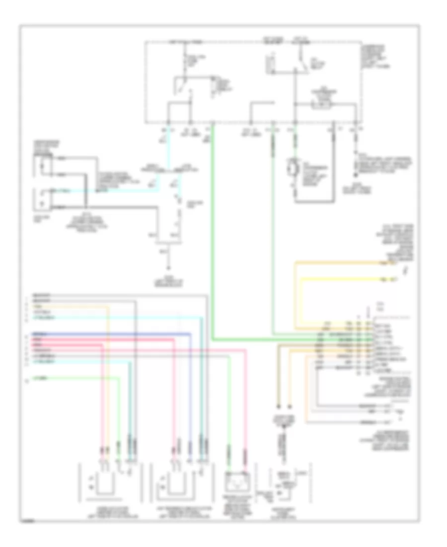
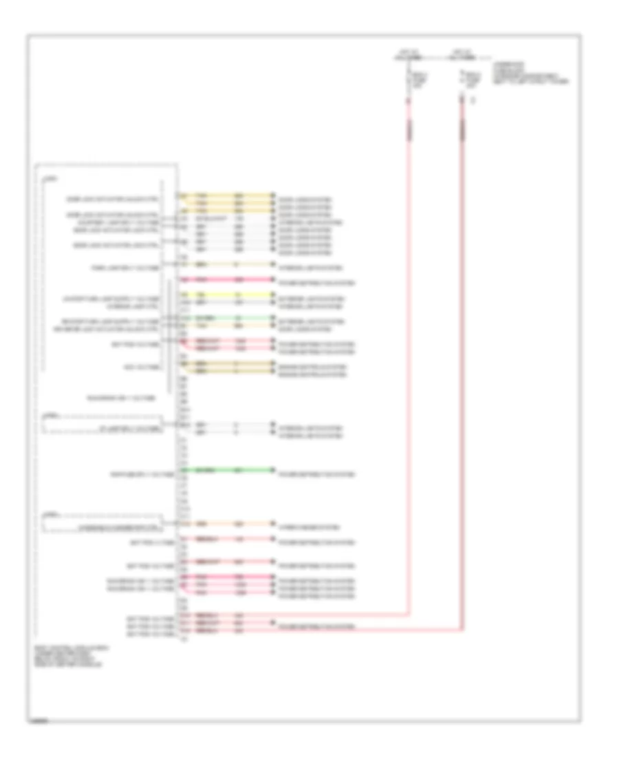
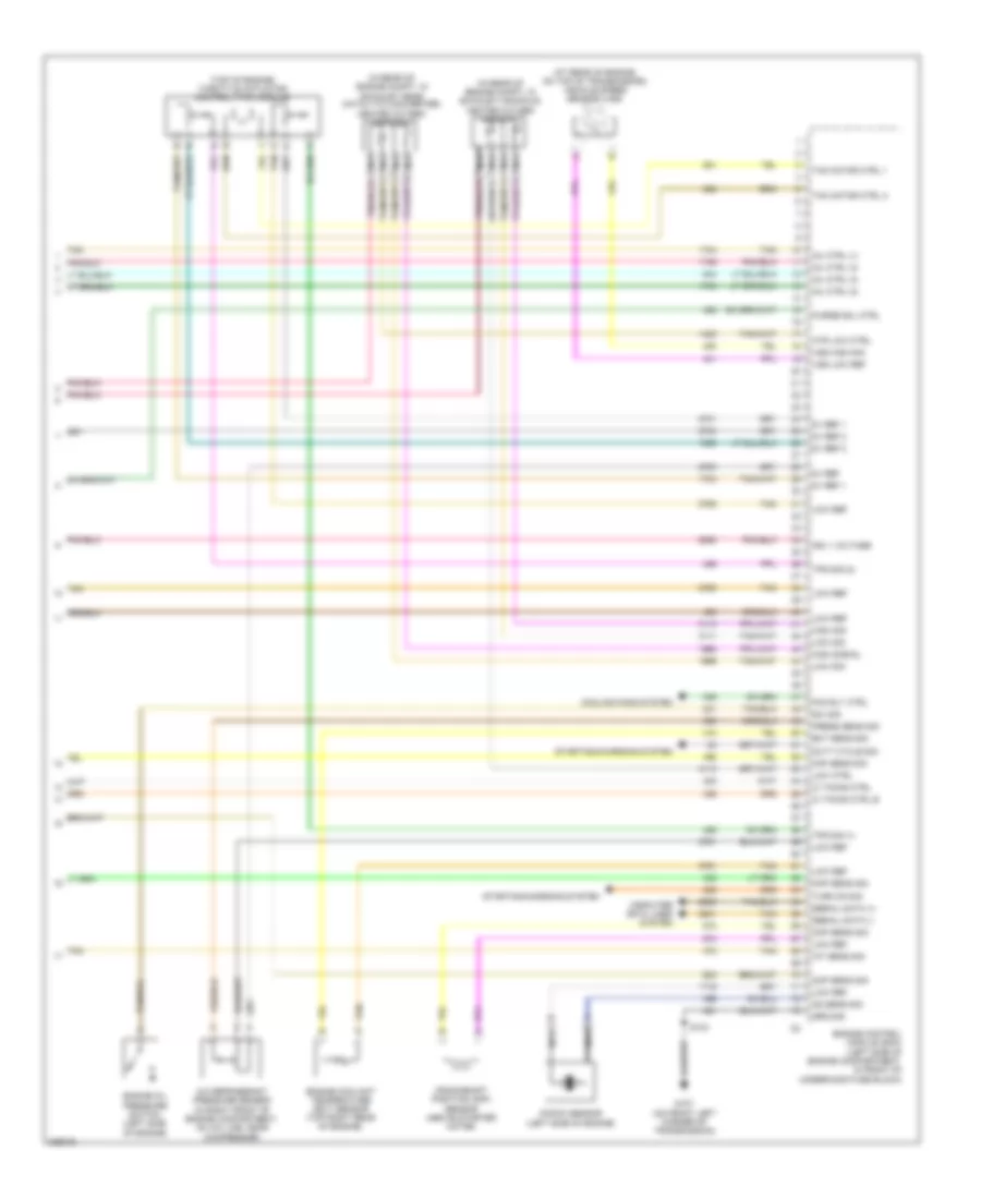
Manual A/C Wiring Diagram (2 of 2) for Chevrolet HHR LS 2006
 https://portal-diagnostov.com/license.html
Automotive Electricians Portal FZCO
Automotive Electricians Portal FZCO
https://portal-diagnostov.com/license.html
https://portal-diagnostov.com/license.html
Automotive Electricians Portal FZCO
Automotive Electricians Portal FZCOList of elements for Manual A/C Wiring Diagram (2 of 2) for Chevrolet HHR LS 2006:
- (2.4l: right side of engine, near exhaust manifold) (2.2l: top right rear of engine) engine coolant temperature (ect) sensor
- (in cooling fan jumper harness approximately 15 cm from g105) s109
- (near engine cooling fan) cooling fan diode
- (not used)
- 2.2l
- 2.4l
- 5v ref
- A/c clutch relay
- A/c compressor clutch (lower left front of engine)
- A/c compressor clutch diode
- A/c refrigerant pressure sensor (in right front of engine compt, on a/c line, near compressor)
- Air temperature actuator (center of dash, left side of hvac module)
- C1 b2
- C2 f11
- C3 c5
- Computer data lines system
- Cool fan fuse 30a
- Cool fan relay
- Coolant temp ind
- Cooling fan
- D12 c1
- E1 c3
- Early production
- Ect sig
- Engine control module (ecm) (left side of engine compt, in front of underhood fuse block)
- F10
- G105 (left front of engine block)
- G109 (on left front shock tower)
- Hot at all times
- Hot in run or start
- Ign
- Instrument panel cluster (ipc)
- Late production
- Logic
- Low ref
- Mode actuator (center of dash, left side of hvac module)
- Nca
- Pnk
- Press sens sig
- Recirculation actuator (behind right side of dash, above blower motor)
- Rly ctrl
- S101 (in forward lamp harness, near left front headlamp, approximately 9 cm from breakout to g109)
- S110 (in cooling fan jumper harness approximately 15 cm from g105)
- Serial data
- Serial data +
- Serial data -
- Tan
- Underhood fuse block (in engine compt, next to left strut tower)
ANTI-LOCK BRAKES
Anti-lock Brakes Wiring Diagram (1 of 2) for Chevrolet HHR LS 2006
 https://portal-diagnostov.com/license.html
Automotive Electricians Portal FZCO
Automotive Electricians Portal FZCO
https://portal-diagnostov.com/license.html
https://portal-diagnostov.com/license.html
Automotive Electricians Portal FZCO
Automotive Electricians Portal FZCOList of elements for Anti-lock Brakes Wiring Diagram (1 of 2) for Chevrolet HHR LS 2006:
- Bat pos volt
- Batt pos volt
- Brake pressure modulator valve
- Computer data lines system
- Electronic brake control module (ecbm) (left side of engine compt, in front of engine control module (ecm))
- G111 (left side of engine compt)
- Hi spd gmlan serial data+
- Hi spd gmlan serial data-
- Ign 1 volt
- Left front wheel speed sensor (wss) (inside left front wheel hub)
- Left rear wheel speed sensor (wss) (inside left rear wheel hub)
- Lf inlet solenoid valve
- Lf outlet solenoid valve
- Lf wheel speed lo ref
- Lf wheel speed sens sig
- Lr inlet solenoid valve
- Lr outlet solenoid valve
- Lr wheel sens sig
- Lr wheel spd sens lo ref
- Nca
- Pnk
- Pump motor control
- Rf inlet solenoid valve
- Rf outlet solenoid valve
- Rf wheel spd sens lo ref
- Rf wheel spd sens sig
- Right front wheel speed sensor (wss) (inside right front wheel hub)
- Right rear wheel speed sensor (wss) (inside right rear wheel hub)
- Rr inlet solenoid valve
- Rr outlet solenoid valve
- Rr wheel spd sens lo ref
- Rr wheel speed sens sig
- Solenoid valve control
- Stop lamp sw sig
- Tan
Anti-lock Brakes Wiring Diagram (2 of 2) for Chevrolet HHR LS 2006
 https://portal-diagnostov.com/license.html
Automotive Electricians Portal FZCO
Automotive Electricians Portal FZCO
https://portal-diagnostov.com/license.html
https://portal-diagnostov.com/license.html
Automotive Electricians Portal FZCO
Automotive Electricians Portal FZCOList of elements for Anti-lock Brakes Wiring Diagram (2 of 2) for Chevrolet HHR LS 2006:
- (not used)
- 2.2l
- 2.4l
- Abs fuse 10a
- Abs fuse 20a
- Abs fuse 30a
- Abs indicator
- Body control module (bcm) (under center dash, below radio, on right side of center console)
- Computer data lines system
- Engine control module (ecm) (left side of engine compt, in front of underhood fuse block)
- Exterior lights system
- Hi spd gmlan ser data +
- Hi spd gmlan ser data -
- Hi spd gmlan serial data +
- Hi spd gmlan serial data -
- Hot at all times
- Hot in run or start
- Ign
- Instrument panel cluster
- Lo spd gmlan serial data
- Logic
- Low spd gmlan ser data
- Pnk
- Stop lamp sw sig
- Tan
- Traction off ind
- Underhood fuse block (in engine compt, next to left strut tower)
ANTI-THEFT
Anti-theft Wiring Diagram for Chevrolet HHR LS 2006
 https://portal-diagnostov.com/license.html
Automotive Electricians Portal FZCO
Automotive Electricians Portal FZCO
https://portal-diagnostov.com/license.html
https://portal-diagnostov.com/license.html
Automotive Electricians Portal FZCO
Automotive Electricians Portal FZCOList of elements for Anti-theft Wiring Diagram for Chevrolet HHR LS 2006:
- 2.2l
- 2.4l
- 5v ref
- A/t
- Acc
- Acc volt sig
- B(+)
- Battery b+
- Body control module (bcm) (under center dash, below radio, on right side of center console)
- Cluster fuse 10a
- Computer data lines system
- Engine control module (ecm) (left side of engine compartment, in front of underhood fuse block)
- Engine controls system
- Exterior lights system
- Fuel inj 1 ctrl
- Fuel inj 2 ctrl
- Fuel inj 3 ctrl
- Fuel inj 4 ctrl
- G109 (on left front shock tower)
- G201 (behind left end of dash)
- G301 (under driver's seat)
- G302 (under front passenger's seat)
- Gmlan serial data
- Gmlan serial data +
- Gmlan serial data -
- Ground
- Hazard switch sig
- Hood ajar sw sig
- Hood ajar switch (center front of engine compt)
- Hood closed sw sig
- Horn relay ctrl
- Horns system
- Hot at all times
- Hvac/ pk3 fuse 10a
- Ignition switch
- Instrument panel cluster (ipc)
- Left front door jamb switch (left "a" pillar between door hinges)
- Left rear door jamb switch (center of left "b" pillar between hinges)
- Lf dr ajar sw sig
- Logic
- Lr dr ajar sw sig
- M/t
- Off
- Off/run/crank
- Pass dr ajar sw sig
- Power distribution system
- Right front door jamb switch (right "a" pillar between door hinges)
- Right rear door jamb switch (center of right "b" pillar between hinges)
- Rr dr ajar sw sig
- Run
- S101
- S201
- S206
- S301
- S302
- Sdm fuse 10a
- Security ind
- Security indicator
- Start
- Tan
- Theft deterrent control module (right side of steering column, at ignition switch)
BODY CONTROL MODULES
Body Control Modules Wiring Diagram (1 of 4) for Chevrolet HHR LS 2006
 https://portal-diagnostov.com/license.html
Automotive Electricians Portal FZCO
Automotive Electricians Portal FZCO
https://portal-diagnostov.com/license.html
https://portal-diagnostov.com/license.html
Automotive Electricians Portal FZCO
Automotive Electricians Portal FZCOList of elements for Body Control Modules Wiring Diagram (1 of 4) for Chevrolet HHR LS 2006:
- 5v ref
- Ambient air temp sens low ref
- Ambient air temp sens sig
- Ambient air temperature sensor (behind right front headlight, on frame rail)
- Bat pos voltage
- Body control module (bcm) (under center dash, below radio, on right side of center console)
- Brake fluid level switch (left rear of engine compartment, attached to master cylinder)
- Brake fluid lvl sens sig
- Brk trans shft intrlck sol sply
- Computer data lines system
- Current sensor sig
- Defogger system
- Door lock lock/unlock sig
- Door locks system
- Exterior lights system
- Fog lmp rly coil sply voltage
- G301 (under driver's seat)
- G401 (under left tail/stop & turn signal light)
- Headlamp high beam rly ctrl
- Headlights system
- Horn rly ctrl
- Horns system
- Interior lights system
- Left turn sig lamp sply voltage
- Lf door ajar sw sig
- Liftgate ajar sw sig
- Liftgate release ctrl
- Liftgate release switch sig
- Low spd gmlan serial data
- Lr door ajar sw isg (sedan)
- Park brake switch (attached to emergency brake)
- Pnk
- Power distribution system
- Power tops system
- Prk brake sw sig
- Prk lamp rly ctrl
- Rear defog rly ctrl
- Rf door ajar sw sig
- Right turn sig lamp sply voltage
- Rr door ajar sw sig (sedan)
- Run/crank rly coil ctrl
- S352
- Sensor low ref
- Shift interlock system
- Sig gnd
- Starting/charging system
- Sunroof enable signal
- Tan
- Trunk, tailgate, fuel doors system
- Windshield wiper mtr prk sw sig
- Windshield wiper sw on sig
- Wiper/washer system
Body Control Modules Wiring Diagram (2 of 4) for Chevrolet HHR LS 2006
 https://portal-diagnostov.com/license.html
Automotive Electricians Portal FZCO
Automotive Electricians Portal FZCO
https://portal-diagnostov.com/license.html
https://portal-diagnostov.com/license.html
Automotive Electricians Portal FZCO
Automotive Electricians Portal FZCOList of elements for Body Control Modules Wiring Diagram (2 of 4) for Chevrolet HHR LS 2006:
- A10
- A11
- A12
- Acc voltage
- B10
- B11
- B12
- Bat pos vltage
- Bat pos voltage
- Bcm 2 fuse 40a
- Bcm 3 fuse 30a
- Body control module (bcm) (under center dash, below radio, on right side of center console)
- C10
- C11
- C12
- Courtesy lamp sply voltage
- D10
- D11
- D12
- Door lock actuator lock ctrl
- Door lock actuator unlock ctrl
- Door locks system
- Driver dr lock actuator unlock ctrl
- Engine controls system
- Exterior lights system
- Hot at all times
- I/p lamp sply voltage
- Interior lamp ctrl
- Interior lights system
- Logic
- Park lamp sply voltage
- Pnk
- Power distribution system
- Rap fuse sply voltage
- Run/crank ign 1 voltage
- Tan
- Underhood fuse block (in engine compartment, next to left strut tower)
- Windshield washer pmp ctrl
- Wiper/washer system
Body Control Modules Wiring Diagram (3 of 4) for Chevrolet HHR LS 2006
 https://portal-diagnostov.com/license.html
Automotive Electricians Portal FZCO
Automotive Electricians Portal FZCO
https://portal-diagnostov.com/license.html
https://portal-diagnostov.com/license.html
Automotive Electricians Portal FZCO
Automotive Electricians Portal FZCOList of elements for Body Control Modules Wiring Diagram (3 of 4) for Chevrolet HHR LS 2006:
- A10
- A11
- A12
- Acc voltage
- Air conditioning system
- B10
- B11
- B12
- Bat pos voltage
- Battery
- Body control module (bcm) (under center dash, below radio, on right side of center console)
- C10
- C11
- C12
- D10
- D11
- D12
- E10
- E11
- E12
- F10
- F11
- F12
- G203 (behind left end of dash)
- Ground
- Head lights system
- Interior lights system
- Logic
- Pnk
- Power distribution system
- Run/crank ign 1 voltage
- Run/crank rly coil ctrl
- Windshield washer pump ctrl
- Wiper/washer system
Body Control Modules Wiring Diagram (4 of 4) for Chevrolet HHR LS 2006
 https://portal-diagnostov.com/license.html
Automotive Electricians Portal FZCO
Automotive Electricians Portal FZCO
https://portal-diagnostov.com/license.html
https://portal-diagnostov.com/license.html
Automotive Electricians Portal FZCO
Automotive Electricians Portal FZCOList of elements for Body Control Modules Wiring Diagram (4 of 4) for Chevrolet HHR LS 2006:
- A/c request sig
- Air conditioning system
- Anti-theft system
- Body control module (bcm) (under center dash, below radio, on right side of center console)
- Computer data lines system
- Crs ctrl set/cst/res/accl sw sig
- Cruise control system
- Defogger system
- Door locks system
- Drl ambient light sens low ref
- Drl ambient light sens sig
- Exterior lights system
- Flash to pass sig
- Front fog lamp sw sig
- Hazard switch sig
- Headlamp dimmer sw hi beam sig
- Headlamp sw headlamps off sig
- Headlamp sw on sig
- Headlamp sw sig
- Headlights system
- High speed gmlan ser bus +
- High speed gmlan ser bus -
- Horn rly ctrl
- Horns system
- I/p lamp dimmer sw sig
- Ignition key resistor signal
- Interior lights system
- Keyless entry program enable sig
- Logic
- Low speed gmlan serial data
- Lr turn sig sw sig
- Off/run/crank voltage
- Park lamp sw on sig
- Pass seat belt indicator
- Power distribution system
- Rear defog rly ctrl
- Rear defog sw sig
- Rr turn sig sw sig
- Seats system
- Security ind sply voltage
- Sens low ref
- Stop lamp sply voltage
- Tan
- Windshield wiper sw low pulse sig
- Wiper/washer system
COMPUTER DATA LINES
Computer Data Lines Wiring Diagram for Chevrolet HHR LS 2006
 https://portal-diagnostov.com/license.html
Automotive Electricians Portal FZCO
Automotive Electricians Portal FZCO
https://portal-diagnostov.com/license.html
https://portal-diagnostov.com/license.html
Automotive Electricians Portal FZCO
Automotive Electricians Portal FZCOList of elements for Computer Data Lines Wiring Diagram for Chevrolet HHR LS 2006:
- (behind left end of dash) g201
- 2.2l
- 2.4l
- A/t
- Body control logic
- Data link connector (dlc) (under lower left of dash)
- Digital radio receiver (right rear corner of vehicle)
- Electronic brake control module (ebcm) (left side of engine compt, in front of engine control module (ecm))
- Electronic power steering (eps) control module
- Engine control module (ecm) (left side of engine compt, in front of underhood fuse block)
- G203 (behind left end of dash)
- High speed gmlan serial data bus +
- High speed gmlan serial data bus -
- Hot at all times
- Inflatable restraint sensing & diagnostic module (sdm) (under center console, forward of park brake)
- Instrument panel cluster (ipc)
- Lighter fuse 15a
- Low speed gm lan serial data
- Low speed gmlan serial data
- M/t
- Module (bcm) (under center dash, below radio, on right side of center console)
- Power distribution system
- Radio
- S200
- S201
- Splice pack sp205 (in i/p harness, behind bcm taped to harness)
- Tan
- Theft deterrent control module (right side of steering column, at ignition switch)
- Transmission control module (tcm) (left side of engine compt)
- Underhood fuse block (in engine compt, next to left strut tower)
- Vehicle communication interface module (vcim) (if equipped) (right rear corner of vehicle)
- W/ abs
- W/ onstar
- W/o abs
- W/o onstar
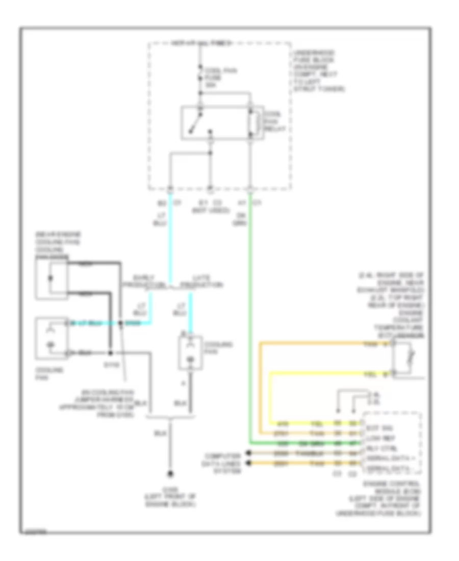
COOLING FAN
Cooling Fan Wiring Diagram for Chevrolet HHR LS 2006
 https://portal-diagnostov.com/license.html
Automotive Electricians Portal FZCO
Automotive Electricians Portal FZCO
https://portal-diagnostov.com/license.html
https://portal-diagnostov.com/license.html
Automotive Electricians Portal FZCO
Automotive Electricians Portal FZCOList of elements for Cooling Fan Wiring Diagram for Chevrolet HHR LS 2006:
- (2.4l: right side of engine, near exhaust manifold) (2.2l: top right rear of engine) engine coolant temperature (ect) sensor
- (in cooling fan jumper harness approximately 15 cm from g105)
- (near engine cooling fan) cooling fan diode
- (not used)
- 2.4l 2.2l
- C1 a1
- C1 b2
- C3 e1
- Computer data lines system
- Cool fan fuse 30a
- Cool fan relay
- Cooling fan
- Early production
- Ect sig
- Engine control module (ecm) (left side of engine compt, in front of underhood fuse block)
- G105 (left front of engine block)
- Hot at all times
- Late production
- Low ref
- Nca
- Rly ctrl
- S109
- S110
- Serial data +
- Serial data -
- Tan
- Underhood fuse block (in engine compt, next to left strut tower)
CRUISE CONTROL
Cruise Control Wiring Diagram for Chevrolet HHR LS 2006
 https://portal-diagnostov.com/license.html
Automotive Electricians Portal FZCO
Automotive Electricians Portal FZCO
https://portal-diagnostov.com/license.html
https://portal-diagnostov.com/license.html
Automotive Electricians Portal FZCO
Automotive Electricians Portal FZCOList of elements for Cruise Control Wiring Diagram for Chevrolet HHR LS 2006:
- (behind left end of dash) g201
- (in steering column harness, behind inflatable restraint steering wheel module)
- (under left side of dash, at top of brake pedal)
- (under left side of dash, at top of clutch pedal)
- 2.2l
- 2.4l
- 5 volt ref
- 5v ref
- A/t
- Accelerator pedal position (app) sensor (near accelerator pedal bracket)
- Anti-lock brakes system
- App sens 1 sig
- App sens 2 sig
- Body control module (bcm) (under center dash, below radio, on right side of center console)
- C2 b10
- C4 e1
- Clutch pedal position (cpp) switch (m/t)
- Cpp sw sig
- Cruise control on ind
- Cruise ctrl sw sig
- Emissions fuse 10a
- Engine control module (ecm) (left side of engine compt, in front of underhood fuse block)
- Eps/str whl cntrl fuse 2a
- Exterior lights system
- Hot at all times
- Hot in acc or run
- Hot in run or start
- Hvac i/p ign fuse 10a
- Inflatable restraint steering wheel module coil (on steering column, behind steering wheel)
- Left steering wheel controls
- Logic
- Low ref
- M/t
- Pnk
- Power distribution system
- Res+
- S208 (w/ accessory electronic control system)
- Set-
- Stop fuse 10a
- Stop lamp sply
- Stop lamp sw sig
- Stop lamp switch
- Stop lamp/ tcc/cruise release switch (under left side of dash, at top of brake pedal)
- Tac mtr ctrl 1
- Tac mtr ctrl 2
- Tan
- Tcc brake sw/cruise
- Throttle actuator control (tac) module (2.2l: top of engine) (2.4l: top of intake manifold)
- Tp sens 1 sig
- Tp sens 2 sig
- Transmission control module (tcm) (left side of engine compt)
- Underhood fuse block (in engine compt, next to left strut tower)
- Vehicle speed sensor (vss) (at rear of engine, on top of transmission)
- Vss hi sig
- Vss high sig
- Vss lo sig
- Vss low sig
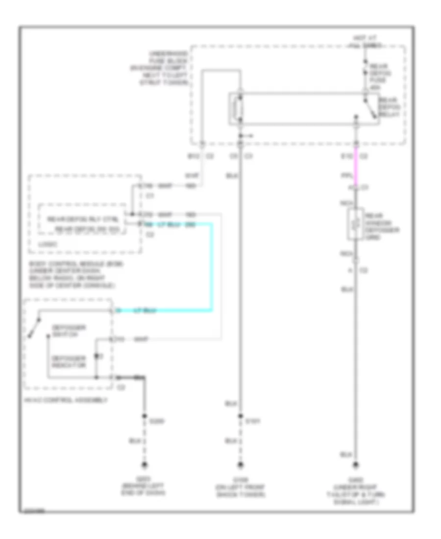
DEFOGGERS
Defoggers Wiring Diagram for Chevrolet HHR LS 2006
 https://portal-diagnostov.com/license.html
Automotive Electricians Portal FZCO
Automotive Electricians Portal FZCO
https://portal-diagnostov.com/license.html
https://portal-diagnostov.com/license.html
Automotive Electricians Portal FZCO
Automotive Electricians Portal FZCOList of elements for Defoggers Wiring Diagram for Chevrolet HHR LS 2006:
- Body control module (bcm) (under center dash, below radio, on right side of center console)
- C2 a
- C2 b12
- C2 e12
- C3 c5
- Defogger indicator
- Defogger switch
- G109 (on left front shock tower)
- G203 (behind left end of dash)
- G402 (under right tail/stop & turn signal light)
- Hot at all times
- Hvac control assembly
- Logic
- Nca
- Rear defog fuse 40a
- Rear defog relay
- Rear defog rly ctrl
- Rear defog sw sig
- Rear window defogger grid
- S101
- S200
- Underhood fuse block (in engine compt, next to left strut tower)
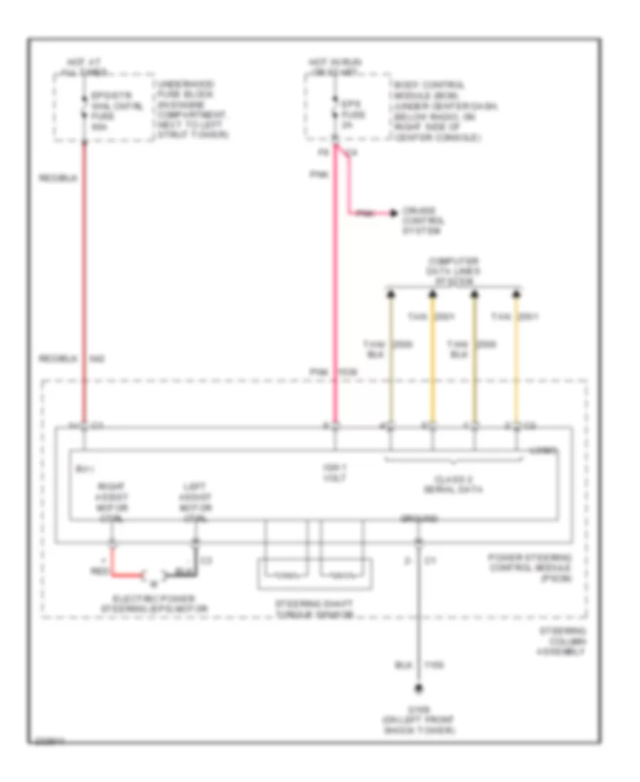
ELECTRONIC POWER STEERING
Electronic Power Steering Wiring Diagram for Chevrolet HHR LS 2006
 https://portal-diagnostov.com/license.html
Automotive Electricians Portal FZCO
Automotive Electricians Portal FZCO
https://portal-diagnostov.com/license.html
https://portal-diagnostov.com/license.html
Automotive Electricians Portal FZCO
Automotive Electricians Portal FZCOList of elements for Electronic Power Steering Wiring Diagram for Chevrolet HHR LS 2006:
- - c3
- B(+)
- Body control module (bcm) (under center dash, below radio, on right side of center console)
- Class 2 serial data
- Computer data lines system
- Cruise control system
- Electric power steering (eps) motor
- Eps fuse 2a
- Eps/str whl cntrl fuse 60a
- G109 (on left front shock tower)
- Ground
- Hot at all times
- Hot in run or start
- Ign 1 volt
- Left assist motor ctrl
- Logic
- Pnk
- Power steering control module (pscm)
- Red
- Right assist motor ctrl
- Steering column assembly
- Steering shaft torque sensor
- Tan
- Tan/
- Underhood fuse block (in engine compartment, next to left strut tower)
ENGINE PERFORMANCE
2.2L VIN F
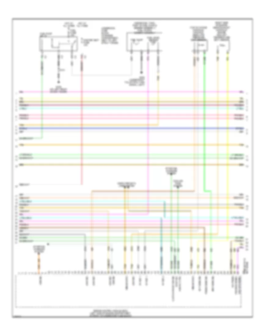
2.2L VIN F, Engine Performance Wiring Diagram (1 of 4) for Chevrolet HHR LS 2006
 https://portal-diagnostov.com/license.html
Automotive Electricians Portal FZCO
Automotive Electricians Portal FZCO
https://portal-diagnostov.com/license.html
https://portal-diagnostov.com/license.html
Automotive Electricians Portal FZCO
Automotive Electricians Portal FZCOList of elements for 2.2L VIN F, Engine Performance Wiring Diagram (1 of 4) for Chevrolet HHR LS 2006:
- (under left side of dash, at top of clutch pedal)
- 5v ref 1
- 5v ref 2
- A11
- Acc
- Acc voltage
- Air conditioning system
- App sig (1)
- App sig (2)
- B(+)
- Body control module (bcm) (under center of dash, below radio, on right side of center console)
- Clutch pedal position (cpp) switch (m/t)
- Clutch rly ctrl
- Clutch strt sw sig
- Cpp sw sig
- Ecm/trans fuse 15a
- Engine control module (ecm) (left side of engine compartment, in front of underhood fuse block)
- Evaporative emission (evap) canister vent solenoid (under rear of vehicle, behind fuel tank attached to evap canister)
- Fuel lvl sens sig
- Fuel tank press sig
- Fuel tank pressure (ftp) sensor (on top of fuel tank)
- G109 (on left front shock tower)
- Hot at all times
- Ign
- Ign 1 voltage
- Ignition switch
- Instrument panel cluster (ipc)
- Logic
- Low ref
- Main rly ctrl
- Malfunc- tion indicator lamp
- Mil ctrl
- Off
- Relay coil ctrl
- Rly ctrl
- Run
- Run/ crank relay
- S101
- S206 (a/t)
- Start
- Starter rly ctrl
- Starting/ charging system
- Stop lmp sw sig
- Tan
- Tcc brk sw sig
- Underhood fuse block (in engine compartment, next to left strut tower)
- Vent sol ctrl
2.2L VIN F, Engine Performance Wiring Diagram (2 of 4) for Chevrolet HHR LS 2006
 https://portal-diagnostov.com/license.html
Automotive Electricians Portal FZCO
Automotive Electricians Portal FZCO
https://portal-diagnostov.com/license.html
https://portal-diagnostov.com/license.html
Automotive Electricians Portal FZCO
Automotive Electricians Portal FZCOList of elements for 2.2L VIN F, Engine Performance Wiring Diagram (2 of 4) for Chevrolet HHR LS 2006:
- (near accelerator pedal bracket) accelerator pedal position (app) sensor
- (top front of engine) fuel injectors
- (top left side of engine) fuel injectors
- 1-4 coil ctrl
- 2-3 coil ctrl
- A11
- B10
- C12
- Cmp sig
- Csi pickup
- Ecm/ pcm fuse 15a
- Emission fuse 10a
- Evaporative emission (evap) canister purge solenoid (on top rear of engine)
- G107 (on front left corner of transmission)
- Gnd
- Hot at all times
- Ic timing ctrl
- Ic timing ctrl b
- Ign coil voltage
- Ignition 1
- Ignition coil
- Ignition control module (icm) (top of engine)
- Inj ign mod fuse 10a
- Interconnect
- Manifold absolute pressure (map) sensor (top left side of engine, at number 3 intake port runner)
- Pnk
- Powertrain relay
- S104 (in fuel injector harness, on top of engine)
- Tan
- Underhood fuse block (in engine compartment, next to left strut tower)
2.2L VIN F, Engine Performance Wiring Diagram (3 of 4) for Chevrolet HHR LS 2006
 https://portal-diagnostov.com/license.html
Automotive Electricians Portal FZCO
Automotive Electricians Portal FZCO
https://portal-diagnostov.com/license.html
https://portal-diagnostov.com/license.html
Automotive Electricians Portal FZCO
Automotive Electricians Portal FZCOList of elements for 2.2L VIN F, Engine Performance Wiring Diagram (3 of 4) for Chevrolet HHR LS 2006:
- (on front left corner of transmission)
- Body control module (bcm) (under center dash, below radio, on right side of center console)
- Cnstr vent fuse 10a
- Fuel pump
- Fuel pump & sender assembly (inside fuel tank, part of fuel pump & sender assembly)
- Fuel pump fuse 15a
- Fuel pump relay
- Fuel sender
- G107
- G109 (on left front shock tower)
- G402 (under right tail/stop & turn signal light)
- Hot at all times
- Hot in acc or run
- I/p ignition fuse 10a
- Iat
- Maf
- Mass air flow (maf)/intake air temperature (iat) sensor (front right of engine compt, attached to air cleaner outlet)
- Pnk
- S101
- S103
- Stop fuse 10a
- Stop lamp switch (under left side of dash, at top of brake pedal)
- Stop lamp/ tcc/cruise release switch
- Tan
- Underhood fuse block (in engine compartment, next to left strut tower)
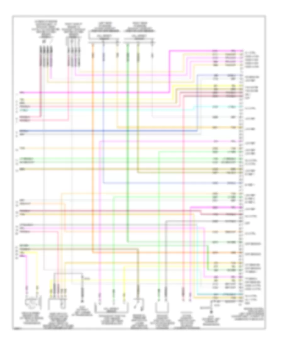
2.2L VIN F, Engine Performance Wiring Diagram (4 of 4) for Chevrolet HHR LS 2006
 https://portal-diagnostov.com/license.html
Automotive Electricians Portal FZCO
Automotive Electricians Portal FZCO
https://portal-diagnostov.com/license.html
https://portal-diagnostov.com/license.html
Automotive Electricians Portal FZCO
Automotive Electricians Portal FZCOList of elements for 2.2L VIN F, Engine Performance Wiring Diagram (4 of 4) for Chevrolet HHR LS 2006:
- (at rear of engine, on top of transmission) vehicle speed sensor (vss)
- (in rear of engine compt, in exhaust manifold) heated oxygen sensor 1
- (in rear of engine compt, in exhaust near catalytic converter) heated oxygen sensor 2
- (top of engine) throttle actuator control (tac) module
- 5v ref
- 5v ref 1
- 5v ref 2
- A/c refrigerant pressure sensor (in right front of engine compartment, on a/c line, near compressor)
- Ckp sens sig
- Cmp sens sig
- Computer data lines system
- Cooling fans system
- Crankshaft position (ckp) sensor (above starter motor)
- Duty cycle sig
- Ect sens sig
- Engine control module (ecm) (left side of engine compartment, in front of underhood fuse block)
- Engine coolant temperature (ect) sensor (top right rear of engine)
- Engine oil pressure switch (left side of engine)
- Fan rly ctrl
- G107 (on front left corner of transmission)
- Ground
- High sig
- High signal
- Htr low ctrl
- Iat sens sig
- Ic timing ctrl
- Ic timing ctrl b
- Ign 1 voltage
- Inj ctrl (1)
- Inj ctrl (2)
- Inj ctrl (3)
- Inj ctrl (4)
- Knock sensor (left side of engine)
- Ks sens sig
- Low ctrl
- Low ref
- Low sig
- Maf sens sig
- Map sens sig
- Nca
- Press sens sig
- Purge sol ctrl
- S103
- Serial data (+)
- Serial data (-)
- Starting/charging system
- Sw sig
- Tac motor ctrl 1
- Tac motor ctrl 2
- Tan
- Tps sig (1)
- Tps sig (2)
- Turn on sig
- Vss high sig
- Vss low ref
2.4L VIN B
2.4L VIN B, Engine Performance Wiring Diagram (1 of 4) for Chevrolet HHR LS 2006
 https://portal-diagnostov.com/license.html
Automotive Electricians Portal FZCO
Automotive Electricians Portal FZCO
https://portal-diagnostov.com/license.html
https://portal-diagnostov.com/license.html
Automotive Electricians Portal FZCO
Automotive Electricians Portal FZCOList of elements for 2.4L VIN B, Engine Performance Wiring Diagram (1 of 4) for Chevrolet HHR LS 2006:
- (in engine compartment, next to left strut tower) underhood fuse block
- 5v ref 1
- 5v ref 2
- A11
- Acc
- Acc voltage
- Accelerator pedal position (app) sensor (near accelerator pedal bracket)
- Accy
- Air conditioning system
- App sensor 1
- App sensor 2
- Bat
- Body control module (bcm) (under center dash, below radio, on right side of center console)
- Cl rly ctrl
- Cpp switch sig
- Crank voltage
- Cruise control system
- Cruise ctrl sig
- Ecm/trans fuse 15a
- Engine control module (ecm) (left side of engine compt, in front of underhood fuse block)
- Evap sol ctrl
- Evaporative emission (evap) canister vent solenoid valve (under rear of vehicle, behind fuel tank attached to evap canister)
- Exterior lights system
- F pmp rly ctrl
- Fuel level sens
- Fuel tank pressure (ftp) sensor (on top of fuel tank)
- G109 (on left front shock tower)
- Hot at all times
- Ign
- Ign 1
- Ignition switch
- Instrument panel cluster (ipc)
- Logic
- Low ref
- Main rly ctrl
- Malfunc- tion indicator lamp
- Mil ctrl
- Off
- Press sens sig
- Rly coil ctrl
- Run
- Run/ crank relay
- S101
- S206 (a/t)
- Start
- Starting/charging system
- Stop lp
- Tan
- Tan a
2.4L VIN B, Engine Performance Wiring Diagram (2 of 4) for Chevrolet HHR LS 2006
 https://portal-diagnostov.com/license.html
Automotive Electricians Portal FZCO
Automotive Electricians Portal FZCO
https://portal-diagnostov.com/license.html
https://portal-diagnostov.com/license.html
Automotive Electricians Portal FZCO
Automotive Electricians Portal FZCOList of elements for 2.4L VIN B, Engine Performance Wiring Diagram (2 of 4) for Chevrolet HHR LS 2006:
- (in engine compartment, next to left strut tower) underhood fuse block
- (in fuel injector harness, on top of engine) s104
- (near top of engine, approximately 13 cm from breakout to ignition coil 1 breakout)
- (on top of engine) ignition coil/module
- (under left side of dash, at top of clutch pedal) (m/t) clutch pedal position (cpp) switch
- A/c refrigerant pressure sensor (in right front of engine compartment,
- A11
- B10
- C12
- Ecm fuse 15a
- Emission fuse 10a
- Evaporative emission (evap) canister purge solenoid valve (on top rear of engine)
- Fuel injectors (top front of engine)
- Fuel injectors (top left side of engine)
- G108 (right rear of engine block)
- Hot at all times
- Ign mod fuse 10a
- Knock sensor (ks) (lower left rear of engine block)
- On a/c line, near compressor)
- Pnk
- Pwr/trn relay
- S105
- S106
- S107
- Tan
- Throttle actuator control (tac) module (top of intake manifold)
2.4L VIN B, Engine Performance Wiring Diagram (3 of 4) for Chevrolet HHR LS 2006
 https://portal-diagnostov.com/license.html
Automotive Electricians Portal FZCO
Automotive Electricians Portal FZCO
https://portal-diagnostov.com/license.html
https://portal-diagnostov.com/license.html
Automotive Electricians Portal FZCO
Automotive Electricians Portal FZCOList of elements for 2.4L VIN B, Engine Performance Wiring Diagram (3 of 4) for Chevrolet HHR LS 2006:
- (inside fuel tank, part of fuel pump & sender assembly) fuel pump & sender assembly
- (right side of engine, near exhaust manifold) engine coolant temperature (ect) sensor
- (top of intake manifold) manifold absolute pressure (map) sensor
- 5v ref 1
- 5v ref 2
- C3 vss low signal
- Clutch start sw sig
- Cnster vent fuse 10a
- Computer data lines system
- Cooling fans system
- Ect sens sig
- Engine control module (ecm) (left side of engine compartment, in front of underhood fuse block)
- Evap sol
- Fan rly ctrl
- Fuel fuse 15a
- Fuel level sensor
- Fuel pump
- Fuel pump relay
- G109 (on left front shock tower)
- G402 (under right tail/stop & turn signal light)
- Gen sig
- Gmlan data
- Hot at all times
- Low ref
- Map sens sig
- Not used) (pins 68 to 73
- Oil press
- Press sens sig
- S101
- Starting/ charging system
- Tan
- Underhood fuse block (in engine compartment, next to left strut tower)
- Vss high signal
2.4L VIN B, Engine Performance Wiring Diagram (4 of 4) for Chevrolet HHR LS 2006
 https://portal-diagnostov.com/license.html
Automotive Electricians Portal FZCO
Automotive Electricians Portal FZCO
https://portal-diagnostov.com/license.html
https://portal-diagnostov.com/license.html
Automotive Electricians Portal FZCO
Automotive Electricians Portal FZCOList of elements for 2.4L VIN B, Engine Performance Wiring Diagram (4 of 4) for Chevrolet HHR LS 2006:
- (at rear of engine, on top of transmission)
- (in rear of engine compartment, in exhaust near catalytic converter) heated oxygen sensor (ho2s) 2
- (left rear of engine) intake camshaft position (cmp) sensor
- (right rear of engine) exhaust camshaft position (cmp) sensor
- (right side of engine, in exhaust manifold) heated oxygen sensor (ho2s) 1
- 5v ref 1
- 5v ref 2
- Ckp sens sig
- Cmp
- Cmp
- Cmp sens sig
- Crankshaft position (ckp) sensor (lower left rear of engine block)
- Engine control module (ecm) (left side of engine compartment, in front of
- Engine oil pressure (eop) switch (lower left rear of engine block)
- Exhaust camshaft position (cmp) actuator solenoid (top front of engine)
- G107 (on front left corner of transmission)
- Gnd
- Hall effect sensor
- Ho2s hi sig
- Ho2s lo ctrl
- Ho2s lo sig
- Iat sens sig
- Ic 1 ctrl
- Ic 2 ctrl
- Ic 3 ctrl
- Ic 4 ctrl
- Ign 1
- Inj 1 ctrl
- Inj 2 ctrl
- Inj 3 ctrl
- Inj 4 ctrl
- Intake camshaft position (cmp) actuator solenoid (top front of engine)
- Ks sens sig
- Low ref
- Maf sens sig
- Mass air flow (maf)/intake air temperature (iat) sensor (right front of engine compt, attached to air cleaner outlet)
- Nca
- S103
- Tac motor
- Tan
- Tp sens 1
- Tp sens 2
- Underhood fuse block)
- Vehicle speed sensor (vss)
EXTERIOR LIGHTS
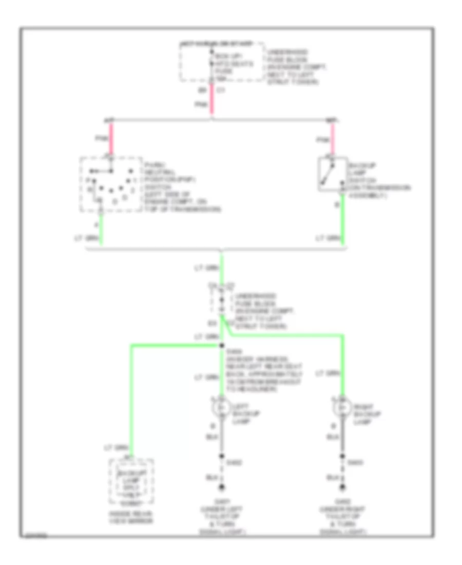
Backup Lamps Wiring Diagram for Chevrolet HHR LS 2006
 https://portal-diagnostov.com/license.html
Automotive Electricians Portal FZCO
Automotive Electricians Portal FZCO
https://portal-diagnostov.com/license.html
https://portal-diagnostov.com/license.html
Automotive Electricians Portal FZCO
Automotive Electricians Portal FZCOList of elements for Backup Lamps Wiring Diagram for Chevrolet HHR LS 2006:
- A/t
- Backup lamp sply volt
- Backup lamp switch (on transmission assembly)
- Bck up/ htd seats fuse 10a
- G401 (under left tail/stop & turn signal light)
- G402 (under right tail/stop & turn signal light)
- Hot in run or start
- Inside rear- view mirror
- Left backup lamp
- Logic
- M/t
- Park/ neutral position (pnp) switch (left side of engine compt, on top of transmission)
- Pnk
- Right backup lamp
- S400
- S402
- S404 (in body harness, near left rear seat back, approximately 18 cm from breakout to headliner)
- Underhood fuse block (in engine compt, next to left strut tower)
Exterior Lamps Wiring Diagram (1 of 2) for Chevrolet HHR LS 2006
 https://portal-diagnostov.com/license.html
Automotive Electricians Portal FZCO
Automotive Electricians Portal FZCO
https://portal-diagnostov.com/license.html
https://portal-diagnostov.com/license.html
Automotive Electricians Portal FZCO
Automotive Electricians Portal FZCOList of elements for Exterior Lamps Wiring Diagram (1 of 2) for Chevrolet HHR LS 2006:
- (early production) (late production)
- A12
- Auto
- B6 c4
- Body control module (bcm) (under center dash, below radio, on right side of center console)
- C1 a9
- C4 a1
- C4 b5
- Center high mounted stop lamp (chmsl)
- Computer data lines system
- E12
- G109 (on left front shock tower)
- G111 (left side of engine compt)
- G201 (behind left end of dash)
- G203 (behind left end of dash)
- G402 (under right tail/stop & turn signal light)
- Ground
- Hazard sw sign
- Hazard switch
- Head
- Headlamp switch
- High speed gmlan serial data bus +
- High speed gmlan serial data bus -
- Hot at all times
- Instrument panel cluster (ipc)
- Interior lights system
- Left
- Left front marker lamp
- Left front park/turn signal/drl lamp
- Left rear stop/turn
- Left turn sig lamp
- Left turn signal ind
- Logic
- Low speed gmlan serial data
- Lr turn sig sw sig
- Off
- Park
- Park lamp relay ctrl
- Park lamp sw sign
- Park lamps fuse 15a 10a
- Prk lamps relay
- Right
- Right front marker lamp
- Right front park/turn signal/drl lamp
- Right rear stop/turn
- Right turn sig lamp
- Right turn signal ind
- Rr turn sig sw sig
- S101
- S102
- S200
- S201
- S900
- Splice pack sp205 (in i/p harness, behind bcm taped to harness)
- Stop lamp sw sign
- Stop lamp switch (under left side of dash, at top of brake pedal)
- Stop lps fuse 10a
- Tan
- Turn signal/ multi- function switch
- Turn switch
- Underhood fuse block (in engine compt, next to left strut tower)
Exterior Lamps Wiring Diagram (2 of 2) for Chevrolet HHR LS 2006
 https://portal-diagnostov.com/license.html
Automotive Electricians Portal FZCO
Automotive Electricians Portal FZCO
https://portal-diagnostov.com/license.html
https://portal-diagnostov.com/license.html
Automotive Electricians Portal FZCO
Automotive Electricians Portal FZCOList of elements for Exterior Lamps Wiring Diagram (2 of 2) for Chevrolet HHR LS 2006:
- (2.2l)
- (2.4l)
- (in body harness, near right rear, approximately 33 cm from breakout to right tail/stop lamp) s403
- (left side of engine compt, in front of engine control module (ecm))
- Electronic brake control module (ebcm)
- Engine control module (ecm) (left side of engine compt, in front of underhood fuse block)
- G401 (under left tail/stop & turn signal light)
- G402 (under right tail/stop & turn signal light)
- Interior lights system
- Left license lamp
- Left rear marker lamp
- Left tail/ stop & turn signal lamp
- Right license lamp
- Right rear marker lamp
- Right tail/ stop & turn signal lamp
- S400
- S402
- S900
- Stop lamp sw sig
- Transmission control module (tcm) (left side of engine compt)
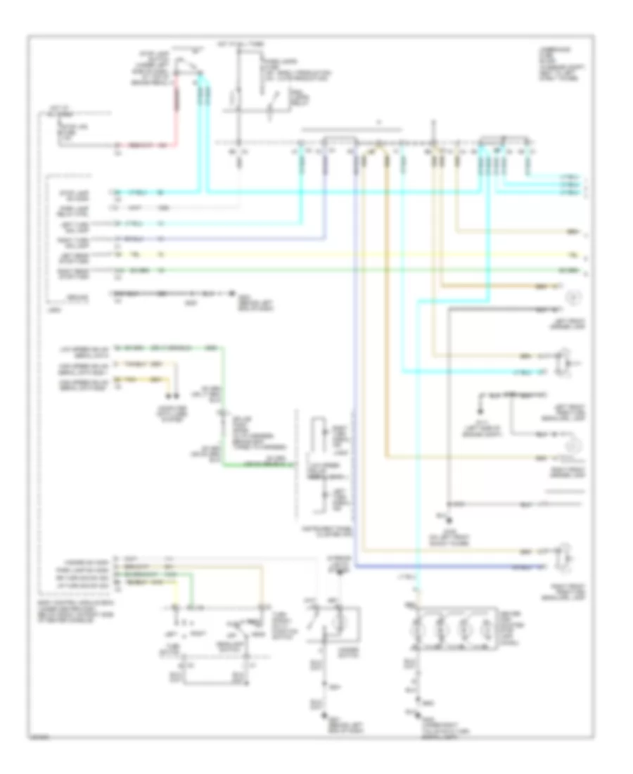
GROUND DISTRIBUTION
Ground Distribution Wiring Diagram (1 of 2) for Chevrolet HHR LS 2006
 https://portal-diagnostov.com/license.html
Automotive Electricians Portal FZCO
Automotive Electricians Portal FZCO
https://portal-diagnostov.com/license.html
https://portal-diagnostov.com/license.html
Automotive Electricians Portal FZCO
Automotive Electricians Portal FZCOList of elements for Ground Distribution Wiring Diagram (1 of 2) for Chevrolet HHR LS 2006:
- (a/t) park/neutral position switch (pnp)
- (a/t) transmission control module (tcm)
- (behind left end of dash) g201
- (under center console, near sdm module)
- (w/ uk3) s208
- 2.2l
- 2.4l
- A/c clutch relay
- A/c compressor clutch
- A/c diode
- B c2
- B c3
- Body control module (bcm)
- C1 d3
- C1 k
- C2 f9
- C2 k
- C3 c5
- Cigar lighter
- Cooling fan diode
- Data link connector (dlc)
- E12 c4
- Early production
- Electronic brake control module (ebcm)
- Engine control module (ecm)
- Engine cooling fan
- Fog lamp relay
- Fog lamp switch
- Fuel pump relay
- G103 (left front corner of engine compt)
- G105 (left front of engine block)
- G107 (on front left corner of transmission)
- G108 (right rear of engine block)
- G109 (on left front shock tower)
- G111 (left side of engine compt)
- G203 (behind left end of dash)
- G306
- Hazard switch
- Hood ajar switch
- Horn
- Horn switch
- Hvac control assembly
- Ignition coil module 1
- Ignition coil module 2
- Ignition coil module 3
- Ignition coil module 4
- Ignition control module
- Inflatable restraint passenger air bag on/off indicator
- Inflatable restraint sensing & diagnostic module (sdm)
- Inflatable restraint steering wheel module coil
- Instrument panel cluster (ipc)
- Late production
- Left front fog lamp
- Left front marker lamp
- Left front park/turn signal/drl lamp
- Left headlamp
- Left steering wheel controls
- Mass air flow (maf)/ intake air tempe- rature (iat) sensor
- Power steering control module
- Radio
- Rear defog relay
- Rear washer relay
- Rear wiper relay
- Rear wiper/washer switch
- Right front fog lamp
- Right front marker lamp
- Right front park/turn signal/drl lamp
- Right headlamp
- Right steering wheel controls
- Run/ crank relay
- S101 (in forward lamp harness, near left front headlamp, approximately 9 cm from breakout to g109)
- S103 (in engine harness, near left rear of engine, approximately 30 cm from breakout to heated oxygen sensor (ho2s) 1)
- S107 (in engine harness, near top of engine, approximately 6 cm from breakout to ignition coil 2 breakout)
- S200 (in i/p harness, near left side of i/p, approximately 29 cm from breakout to g203)
- S201 (in i/p harness, near center console, approximately 18 cm from breakout to inflatable restraint passenger air bag on/off indicator)
- S202 (in steering column harness, behind inflatable restraint steering wheel module)
- Theft deterrent control module
- Turn signal/ multifunction switch
- Underhood fuse block (in engine compt, next to left strut tower)
- Washer pump relay
- Windshield wiper motor
- Wiper relay
Ground Distribution Wiring Diagram (2 of 2) for Chevrolet HHR LS 2006
 https://portal-diagnostov.com/license.html
Automotive Electricians Portal FZCO
Automotive Electricians Portal FZCO
https://portal-diagnostov.com/license.html
https://portal-diagnostov.com/license.html
Automotive Electricians Portal FZCO
Automotive Electricians Portal FZCOList of elements for Ground Distribution Wiring Diagram (2 of 2) for Chevrolet HHR LS 2006:
- (w/ onstar)
- (w/o onstar)
- A c2
- At shift lock control solenoid
- Audio amplifier
- Battery
- Battery current sensor
- Body control module
- Body control module (bcm)
- Brake fluid level switch
- Center high mounted stop lamp (chmsl)
- Console auxiliary power outlet
- Console flood lamp
- Digital radio receiver
- Dome lamp
- Door latch liftgate
- Driver back heated seat element
- Driver door lock switch
- Driver heated seat control module
- Driver seat adjuster switch
- Fuel pump & sender assembly
- G301 (under driver's seat)
- G302 (under front passenger's seat)
- G401 (under left tail/stop & turn signal light)
- G402 (under right tail/stop & turn signal light)
- G403 (right rear corner of vehicle)
- Inflatable restraint passenger presence system (pps) module
- Inside rearview mirror
- Left backup lamp
- Left front door jamb switch
- Left license lamp
- Left rear door jamb switch
- Left rear marker lamp
- Left tail/stop & turn signal lamp
- Liftgate release switch
- Lumbar adjuster switch
- Master window switch
- Outside rearview mirror switch
- Passenger back heated seat element
- Passenger door lock switch
- Passenger heated seat control module
- Performance enhanced audio
- Rear window defogger grid
- Rear window wiper motor
- Remote control door lock receiver
- Right backup lamp
- Right front door jamb switch
- Right front door, approximately 18 cm from s307)
- Right license lamp
- Right rear door jamb switch
- Right rear marker lamp
- Right tail/stop & turn signal lamp
- S301 (in body harness, near center console, approximately 29 cm 29 cm from s300)
- S303 (in headliner harness, near sunroof, approximately 11cm from breakout to c397)
- S315 (in seat harness, under passenger seat, between heated seat module c314)
- S400 (in body harness, near right tail lamp, approximately 27 cm from breakout to g402)
- S401 (in body harness, right side of rear compartment, approximately 6 cm from breakout to digital radio receiver)
- S402 (in body harness, near left rear tail lamp, approximately 11 cm from g401 breakout)
- S500 (in lf door harness, behind trim panel, approximately 17 cm from breakout to mirror motor)
- S900 (in liftgate harness, in rear liftgate, approximately 16 cm from breakout to rear wiper motor)
- Sunroof control module
- Sunroof switch
- Vehicle communication interface module
- W/ s-band digital audio system/ onstar
- W/o s-band digital audio system/ onstar
HEADLIGHTS
Headlights Wiring Diagram for Chevrolet HHR LS 2006
 https://portal-diagnostov.com/license.html
Automotive Electricians Portal FZCO
Automotive Electricians Portal FZCO
https://portal-diagnostov.com/license.html
https://portal-diagnostov.com/license.html
Automotive Electricians Portal FZCO
Automotive Electricians Portal FZCOList of elements for Headlights Wiring Diagram for Chevrolet HHR LS 2006:
- Ambient light sensor (on top center of dash)
- Auto
- Body control module (bcm) (under center dash, below radio, on right side of center console)
- Computer data lines system
- Fog lamp fuse 15a
- Fog lamp relay
- Fog lamp switch
- Fog lmp rly ctrl
- Fog lmp sw sig
- Ftp
- Ftp sw sig
- G109 (on left front shock tower)
- G111 (left side of engine compt)
- G201 (behind left end of dash)
- Head
- Headlamp dimmer sw
- Headlamp sw off sig
- Headlamp sw on sig
- Headlamp sw sig
- Hi beam relay
- Hi beam rly ctrl
- High beam
- High beam ind
- Hot at all times
- Ign
- Instrument panel cluster (ipc)
- Interior lights system
- Left front fog lamp
- Left headlamp
- Lo beam relay
- Logic
- Low
- Low beam
- Lt hi beam fuse 10a
- Lt lo beam fuse 10a
- Lt sens low ref
- Lt sens sig
- Off
- Park
- Right front fog lamp
- Right headlamp
- Rt hi beam fuse 10a
- Rt lo beam fuse 10a
- S101
- S102
- S201
- Serial data
- Turn signal/ multifunction switch
- Underhood fuse block (in engine compt, next to left strut tower)
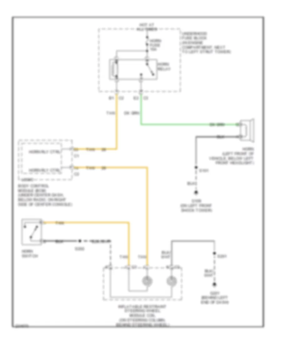
HORN
Horn Wiring Diagram for Chevrolet HHR LS 2006
 https://portal-diagnostov.com/license.html
Automotive Electricians Portal FZCO
Automotive Electricians Portal FZCO
https://portal-diagnostov.com/license.html
https://portal-diagnostov.com/license.html
Automotive Electricians Portal FZCO
Automotive Electricians Portal FZCOList of elements for Horn Wiring Diagram for Chevrolet HHR LS 2006:
- B1 c2
- Body control module (bcm) (under center dash, below radio, on right side of center console)
- E2 c3
- G109 (on left front shock tower)
- G201 (behind left end of dash)
- Horn (left front of vehicle, below left front headlight)
- Horn fuse 10a
- Horn relay
- Horn rly ctrl
- Horn switch
- Hot at all times
- Inflatable restraint steering wheel module coil (on steering column, behind steering wheel)
- Logic
- S101
- S201
- S202
- Tan
- Underhood fuse block (in engine compartment, next to left strut tower)
INSTRUMENT CLUSTER
Instrument Cluster Wiring Diagram for Chevrolet HHR LS 2006
 https://portal-diagnostov.com/license.html
Automotive Electricians Portal FZCO
Automotive Electricians Portal FZCO
https://portal-diagnostov.com/license.html
https://portal-diagnostov.com/license.html
Automotive Electricians Portal FZCO
Automotive Electricians Portal FZCOList of elements for Instrument Cluster Wiring Diagram for Chevrolet HHR LS 2006:
- (behind left end of dash) g201
- (center of left "b" pillar between hinges) left rear door jamb switch
- (center of right "b" pillar between hinges) right rear door jamb switch
- (left "a" pillar between door hinges) left front door jamb switch
- (right "a" pillar between door hinges) rear front door jamb switch
- 2.2l
- 2.4l
- Abs ind
- Air bag ind
- Bat
- Bat pos volt
- Body control module (bcm) (under center dash, below radio, on right side of center console)
- Brake fluid level switch (left rear of engine compt, attached to master cylinder)
- Brake fluid lvl
- Brake ind
- C1 c4
- C1 h
- Charging ind
- Cluster fuse 10a
- Computer data lines system
- Dic sw sig
- Driver information center (dic)
- Engine control module (ecm) (left side of engine compt, in front of underhood fuse block)
- Engine control system
- Engine controls system
- Engine coolant temperature ind
- Engine oil pressure (eop) switch (2.2l: left side of engine) (2.4l: lower left rear of engine block)
- Fog lamp ind
- Fuel level
- Fuel lvl sens sig
- Fuel pump & sender assembly (inside fuel tank, part of fuel pump & sender assembly)
- G201 (behind left end of dash)
- G301 (under driver's seat)
- G302 (under front passenger's seat)
- Gmlan ser data
- Gmlan ser data+
- Gmlan ser data-
- Gmlan serial data
- Gnd
- H c2
- High beam ind
- Hot at all times
- Hot in run or start
- Hvac/ ip ign fuse 10a
- Ign
- Ign 1 volt
- Inflatable restraint steering wheel module coil (on steering column, behind steering wheel)
- Info
- Instrument panel cluster (ipc)
- Left steering wheel controls
- Left turn ind
- Lf dr ajar sw
- Logic
- Low ref
- Lr dr ajar sw
- Malfunction ind
- Mil ctrl
- Oil level ind
- Oil pres sw sig
- Park brake sw
- Park brake switch (in center console, attached to emergency brake)
- Pnk
- Power distribution system
- Reset/ select
- Rf dr ajar sw
- Right turn ind
- Rr dr ajar sw
- S201
- S301
- S302
- Seat belt ind
- Security ind
- Security ind sig
- Security ind sply volt
- Speedometer
- Tachometer
- Tan
- Traction off ind
- Up-shift ind
INTERIOR LIGHTS
Courtesy Lamps Wiring Diagram for Chevrolet HHR LS 2006
 https://portal-diagnostov.com/license.html
Automotive Electricians Portal FZCO
Automotive Electricians Portal FZCO
https://portal-diagnostov.com/license.html
https://portal-diagnostov.com/license.html
Automotive Electricians Portal FZCO
Automotive Electricians Portal FZCOList of elements for Courtesy Lamps Wiring Diagram for Chevrolet HHR LS 2006:
- (in headliner harness, near overhead console, approximately 26 cm from breakout to c397) s316
- (not used)
- A10
- Battery+
- Body control module (bcm) (under center dash, below radio, on right side of center console)
- Ctsy lps ctrl
- Dome
- Dome lamp
- Door
- Driver's seat)
- G301 (under
- G302 (under front passenger's seat)
- G401 (under left tail/stop & turn signal light)
- G402 (under right tail/stop & turn signal light)
- Ground
- Hot at all times
- Inside rearview mirror
- Int light fuse 10a
- Left front door jamb switch (left "a" pillar between door hinges)
- Left rear door jamb switch (center of left "b" pillar between hinges)
- Lf door ajar
- Liftgate ajar
- Liftgate door latch (bottom center of liftgate)
- Logic
- Lr door ajar
- Off
- Reading
- Rf door ajar
- Right front door jamb switch (right "a" pillar between door hinges)
- Right rear door jamb switch (center of right "b" pillar between hinges)
- Rr door ajar
- S301
- S302
- S303
- S310 (in headliner harness, near dome lamp, approximately 66 cm from breakout to dome lamp)
- S900
- W/ onstar
- W/o onstar
Instrument Illumination Wiring Diagram for Chevrolet HHR LS 2006
 https://portal-diagnostov.com/license.html
Automotive Electricians Portal FZCO
Automotive Electricians Portal FZCO
https://portal-diagnostov.com/license.html
https://portal-diagnostov.com/license.html
Automotive Electricians Portal FZCO
Automotive Electricians Portal FZCOList of elements for Instrument Illumination Wiring Diagram for Chevrolet HHR LS 2006:
- (early production) (late production)
- (in body harness, near center console, approximately 11 cm from breakout to sdm) s311
- (in body harness, near right rear, approximately 33 cm from breakout to right tail/stop lamp) s403
- (in steering column harness, behind inflatable restraint steering wheel module) (w/ accessory steering wheel) s207
- (not used)
- A/t shift lock control solenoid (at gear selector)
- B12
- Backlighting
- Battery+
- Body control module (bcm) (under center dash, below radio, on right side of center console)
- C3 b
- C4 a1
- Computer data lines system
- Console flood lamp
- Dimmer low ref
- Dimmer sig
- Driver door lock switch
- Driver's seat)
- Exterior lights system
- Fog lamp switch
- G201 (behind left end of dash)
- G203 (behind left end of dash)
- G301 (under
- G301 (under driver's seat)
- G302 (under front passenger's seat)
- G401 (under left tail/stop & turn signal light)
- Gmlan serial data
- Ground
- Hazard switch
- Hot at all times
- Hvac control assembly
- I/p dimmer switch
- Inflatable restraint steering wheel module coil (on steering column, behind steering wheel)
- Instrument panel cluster (ipc)
- Int light fuse 10a
- Left steering wheel controls
- Logic
- Outside rearview mirror switch
- Park lamp relay
- Park lamps fuse 15a 10a
- Passenger door lock switch
- Pk lmp rly ctrl
- Prndl lamp
- Radio
- Rear wiper/washer switch
- Right steering wheel controls (w/ accessory steering wheel)
- S201
- S208 (w/ accessory steering wheel)
- S300
- S301
- S303
- S500
- Underhood fuse block (in engine compt, next to left strut tower)
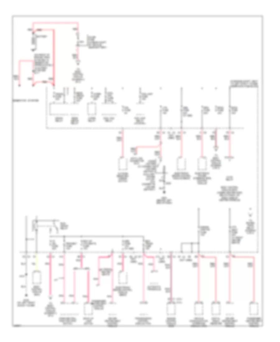
POWER DISTRIBUTION
Power Distribution Wiring Diagram (1 of 3) for Chevrolet HHR LS 2006
 https://portal-diagnostov.com/license.html
Automotive Electricians Portal FZCO
Automotive Electricians Portal FZCO
https://portal-diagnostov.com/license.html
https://portal-diagnostov.com/license.html
Automotive Electricians Portal FZCO
Automotive Electricians Portal FZCOList of elements for Power Distribution Wiring Diagram (1 of 3) for Chevrolet HHR LS 2006:
- (2.2l)
- (2.4l)
- (in engine compt, next to left strut tower) underhood fuse block
- (not used)
- (on front of engine, from starter to generator approximately 15 cm from starter) s111
- 50a
- A/t
- A10
- A2 c3
- Abs fuse 10a (w/ abs)
- Abs fuse 30a (w/ abs)
- Automatic transaxle
- B11
- Back up lamp switch
- Battery
- Bck up/ htd seats fuse 10a
- Bcm2 fuse 40a
- Bcm3 fuse 30a
- Body control module (bcm)
- Body control module (bcm) (under center dash, below radio, on right side of center console)
- C1 b9
- C1 c12
- C1 e
- C2 b3
- C2 f6
- C3 a3
- C3 c5
- C3 d6 (not used)
- C4 a4
- C4 b1
- C4 c2
- C4 e2
- C6 a
- Cigar lighter (w/ cigarette lighter ashtray) auxiliary power outlet (w/o cigarette lighter ashtray)
- Cool fan fuse 30a
- Cool fan relay
- Crank fuse 30a
- Crank relay
- D10 c3
- Data link connector (dlc)
- Digital radio receiver
- Driver heated seat control module
- Ecm/ trans fuse 15a
- Electronic brake control module (ebcm)
- Electronic power steering (eps) control module
- Engine control module (ecm)
- Eps fuse 60a
- Fog lamp fuse 15a
- Fog lamp relay (uplevel)
- G109 (on left front shock tower)
- G203 (behind left end of dash)
- Generator
- Htd seat fuse 20a (w/ front heated seats)
- Hvac relay
- I/p ign fuse 20a
- Inline fuse (in rear compt of vehicle, near battery)
- Ltr fuse 15a
- M/t
- Mir fuse 5a
- Outside rearview mirror switch
- Park/neutral position (pnp) switch
- Passenger heated seat control module
- Pnk
- Prk/neut fuse 10a
- Rear defog fuse 40a
- Rear defog relay
- Red
- Run/ crank relay
- S-band onstar fuse 10a
- S101
- S200
- Starter
- To body control module (diagram 2 of 3)
- To body control module (diagram 3 of 3)
- To power- train relay (diagram 2 of 3)
- Transmission control module (tcm)
- Vehicle communication interface module (vcim)
- W/ front heated seats
- Wiper fuse 25a
- Wiper relay
Power Distribution Wiring Diagram (2 of 3) for Chevrolet HHR LS 2006
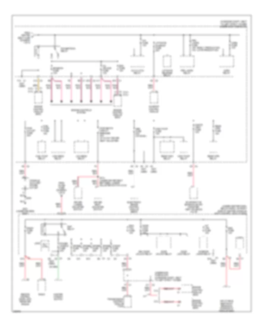 https://portal-diagnostov.com/license.html
Automotive Electricians Portal FZCO
Automotive Electricians Portal FZCO
https://portal-diagnostov.com/license.html
https://portal-diagnostov.com/license.html
Automotive Electricians Portal FZCO
Automotive Electricians Portal FZCOList of elements for Power Distribution Wiring Diagram (2 of 3) for Chevrolet HHR LS 2006:
- (2.2l)
- (2.4l)
- (early production) (late production)
- (in engine compt, next to left strut tower) underhood fuse block
- (not used)
- (under center dash, below radio, on right side of center console) body control module (bcm)
- 2.2l
- 2.4l
- A/c clutch relay
- A/c fuse 10a
- A10 c2
- A11
- A11 c2
- A5 c3
- A5 c4
- A9 c2
- Abs fuse 20a (uplevel)
- B10
- Between lumbar adjuster switch c315)
- C1 b10
- C1 d9
- C1 f12
- C10
- C2 b10
- C2 c12
- C3 c5
- C3 d4
- C4 e8
- C5 c2
- C5 c4
- Cnstr vent fuse 10a
- Console auxiliary power outlet
- D1 c3
- D10
- Door lock fuse 15a
- Door lock relay
- Door unlock relay
- Driver lumbar adjuster switch
- Driver seat adjuster switch
- Drv door unlock relay
- E10
- Ecm fuse 15a
- Ecm/ tcm fuse 10a
- Electronic brake control module (ebcm)
- Emission fuse 10a
- Engine control module (ecm)
- Engine controls system
- Evaporative emission (evap) canister vent solenoid valve
- F7 c1
- From heated c seat fuse (diagram 1 of 3)
- From inline fuse (diagram 1 of 3)
- Fuel pump fuse 15a
- Fuel pump relay
- G301 (under driver's seat)
- High beam relay
- Horn fuse 10a
- Horn relay
- Inflatable restraint sensing & diagnostic module (sdm)
- Inj ign mod fuse 10a
- Int lps fuse 10a
- Interior lamps relay
- Liftgate release relay
- Liftgate/ sunroof fuse 20a
- Logic
- Low beam relay
- M/t
- Master window switch
- Power window fuse 30a
- Powertrain relay
- Prk lamps fuse 15a 10a
- Prk lamps relay
- Pwr outlet fuse 20a
- Pwr seats circuit breaker 30a (w/ 6 way driver seat adjuster)
- Radio
- Radio fuse 15a
- Rap relay
- Rear wpr fuse 15a
- Rear wpr relay
- Rear wsw relay
- Remote control door lock receiver (rcdlr)
- Rly ctrl
- S roof fuse 15a
- S300
- Sdm fuse 10a
- Spare fuse 10a
- Spare fuse 25a
- Spare fuse 2a
- Sunroof control module
- Transmission control module (tcm)
- Underhood fuse block (in engine compt, next to left strut tower)
- Wsw pump fuse 15a
- Wsw pump relay
Power Distribution Wiring Diagram (3 of 3) for Chevrolet HHR LS 2006
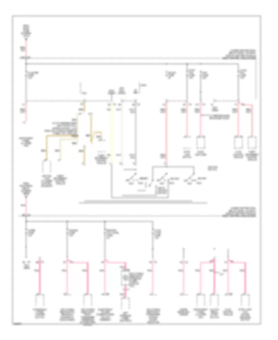 https://portal-diagnostov.com/license.html
Automotive Electricians Portal FZCO
Automotive Electricians Portal FZCO
https://portal-diagnostov.com/license.html
https://portal-diagnostov.com/license.html
Automotive Electricians Portal FZCO
Automotive Electricians Portal FZCOList of elements for Power Distribution Wiring Diagram (3 of 3) for Chevrolet HHR LS 2006:
- (in i/p harness near ignition switch, approximately 4 cm from inflatable steering wheel coil module) s206
- (not used)
- (under center dash, below radio, on right side of center console) body control module (bcm)
- 5v ref
- A/t
- A8 c3
- Acc
- Air bag fuse 10a
- Amp fuse 20a
- Audio amplifier
- C1 c
- C3 a6
- C3 d6
- C4 d3
- C4 e6
- C4 f5
- Cluster fuse 10a
- Clutch pedal start switch
- D11
- D12 c3
- Electronic power steering (eps) column assembly
- Eps/str whl cntrl fuse 2a
- From bcm2 fuse (diagram 1 of 3)
- From run/crank relay (diagram 1 of 3)
- Hvac control module
- Hvac/ ip ign fuse 10a
- Hvac/ pk3 fuse 10a
- Ign sw fuse 2a
- Ignition lock cylinder control solenoid
- Ignition switch
- Inflatable restraint front passenger presence system (pps) module
- Inflatable restraint passenger air bag on/off indicator
- Inflatable restraint steering wheel module coil
- Inflatable restraints sensing & diagnostic module (sdm)
- Inside rearview mirror
- Instrument panel cluster (ipc)
- Key-in ignition switch
- Left steering wheel controls
- Logic
- M/t
- Off
- Off/ run/ crank
- Pnk
- Pnk c
- Run
- Run/ crank
- Start
- Stop lamp switch
- Stop lamp/ tcc/ cruise release switch
- Stop lps fuse 10a
- Theft deterrent control module
- W/ performance enhanced audio
- Windshield wiper/ washer switch
- Wiper fuse 10a
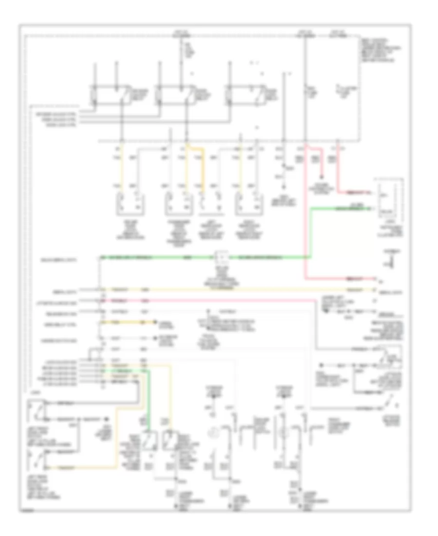
POWER DOOR LOCKS
Power Door Locks Wiring Diagram for Chevrolet HHR LS 2006
 https://portal-diagnostov.com/license.html
Automotive Electricians Portal FZCO
Automotive Electricians Portal FZCO
https://portal-diagnostov.com/license.html
https://portal-diagnostov.com/license.html
Automotive Electricians Portal FZCO
Automotive Electricians Portal FZCOList of elements for Power Door Locks Wiring Diagram for Chevrolet HHR LS 2006:
- (under driver's seat) g301
- (under front passenger's seat) g302
- (under left tail/stop & turn signal light) g401
- Ajar switch
- Antenna
- B(+)
- Body control module (bcm) (under center dash, below radio, on right side of center console)
- Cluster fuse 10a
- D10
- Door lock ctrl
- Door lock relay
- Door unlock ctrl
- Door unlock relay
- Dr door unlock ctrl
- Dr door unlock relay
- Dr lck fuse 15a
- Driver door latch (rear of driver's door)
- Driver door lock switch
- E12
- Exterior lights system
- Front passenger door lock switch
- G203 (behind left end of dash)
- G301 (under driver's seat)
- G402 (under right tail/stop & turn signal light)
- Gmlan
- Gmlan serial data
- Ground
- Hazard switch sig
- Horn relay ctrl
- Horns system
- Hot at all times
- Instrument panel cluster (ipc)
- Interior lights system
- Left front door jamb switch (left "a" pillar between door hinges)
- Left rear door jamb switch (center of left "b" pillar between hinges)
- Left rear door latch (rear of left rear door)
- Lf dr ajar sw sig
- Liftgate ajar sw sig
- Liftgate door latch (bottom center of liftgate)
- Liftgate release switch
- Lock
- Lock/unlock sig
- Logic
- Lr dr ajar sw sig
- Nca
- Pass dr ajar sw sig
- Passenger door latch (rear of front passenger's door)
- Power distribution system
- Rdo fuse 10a
- Release sw sig
- Remote control door lock receiver (rcdlr) (behind left rear quarterpanel)
- Right front door jamb switch (right "a" pillar between door hinges)
- Right rear door jamb switch (center of right "b" pillar between hinges)
- Right rear door latch (rear of right rear door)
- Rr dr ajar sw sig
- S200
- S301
- S302
- S312 (near center console, approximately 10 cm from breakout to bcm)
- S402
- S500
- S900
- Serial data
- Splice pack sp205 (in i/p harness, behind bcm taped to harness)
- Tan
- Trunk, tailgate, fuel doors system
- Unlock
POWER MIRRORS
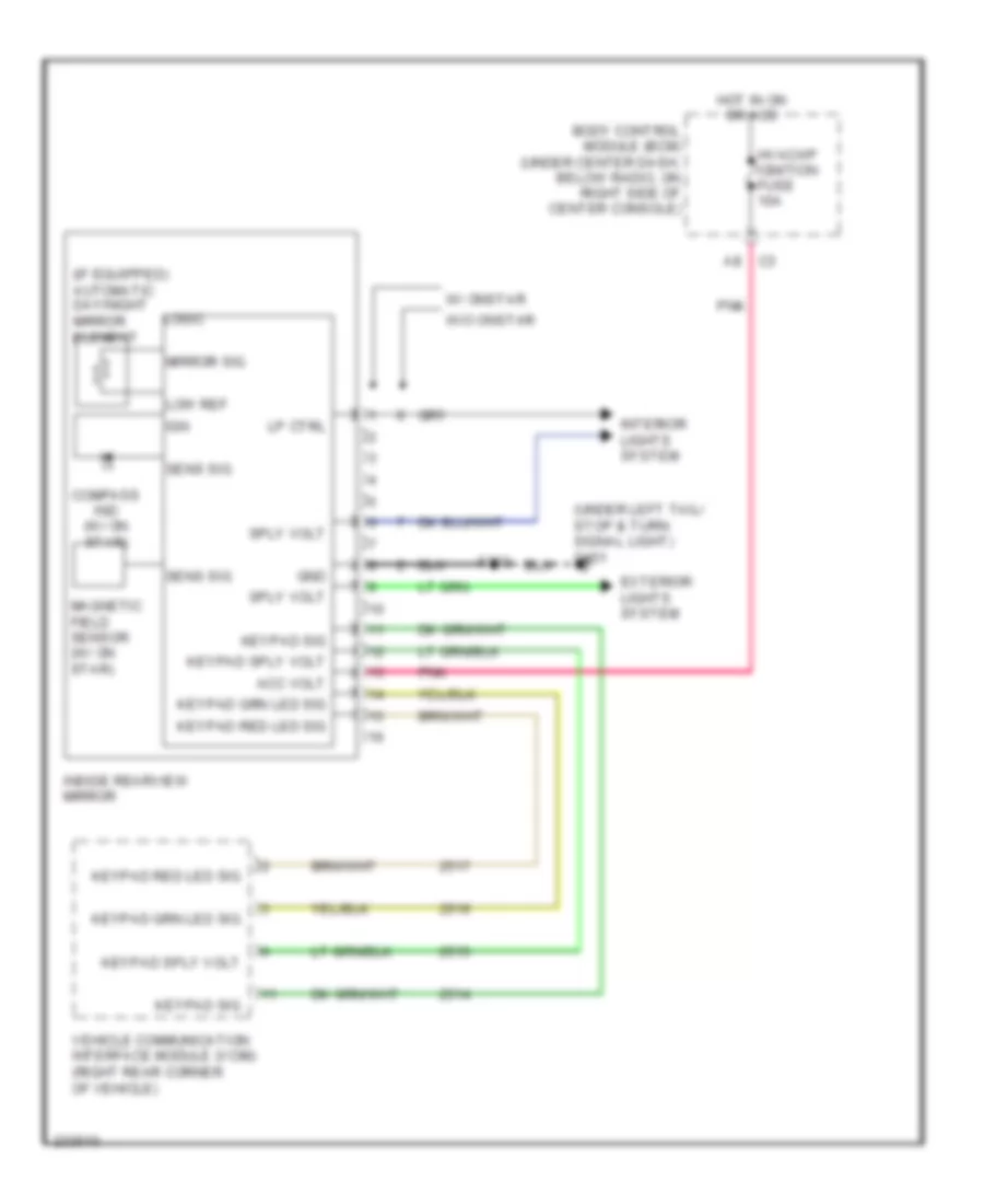
Automatic Day/Night Mirror Wiring Diagram for Chevrolet HHR LS 2006
 https://portal-diagnostov.com/license.html
Automotive Electricians Portal FZCO
Automotive Electricians Portal FZCO
https://portal-diagnostov.com/license.html
https://portal-diagnostov.com/license.html
Automotive Electricians Portal FZCO
Automotive Electricians Portal FZCOList of elements for Automatic Day/Night Mirror Wiring Diagram for Chevrolet HHR LS 2006:
- (if equipped) automatic day/night mirror element
- (under left tail/ stop & turn signal light) g401
- Acc volt
- Body control module (bcm) (under center dash, below radio, on right side of center console)
- Compass ind (w/ on star)
- Exterior lights system
- Gnd
- Hot in on or acc
- Hvac/i/p ignition fuse 10a
- Ign
- Inside rearview mirror
- Interior lights system
- Keypad red led sig
- Keypad sig
- Keypad sply volt
- Logic
- Low ref
- Lp ctrl
- Magnetic field sensor (w/ on star)
- Mirror sig
- Pnk
- S303
- Sens sig
- Sply volt
- Vehicle communication interface module (vcim) (right rear corner of vehicle)
- W/ onstar
- W/o onstar
Power Mirrors Wiring Diagram for Chevrolet HHR LS 2006
 https://portal-diagnostov.com/license.html
Automotive Electricians Portal FZCO
Automotive Electricians Portal FZCO
https://portal-diagnostov.com/license.html
https://portal-diagnostov.com/license.html
Automotive Electricians Portal FZCO
Automotive Electricians Portal FZCOList of elements for Power Mirrors Wiring Diagram for Chevrolet HHR LS 2006:
- Down
- Driver
- Driver outside rearview mirror motor (front of driver's door)
- G301 (under driver's seat)
- Hot at all times
- Interior lights system
- Left
- Left/ right
- Mirrors fuse 5a
- Nca
- Outside rearview mirror switch
- Passenger
- Passenger outside rearview mirror motor (front of front passenger's door)
- Right
- S500
- Underhood fuse block (in engine compt, next to left strut tower)
- Up/ down
POWER SEATS
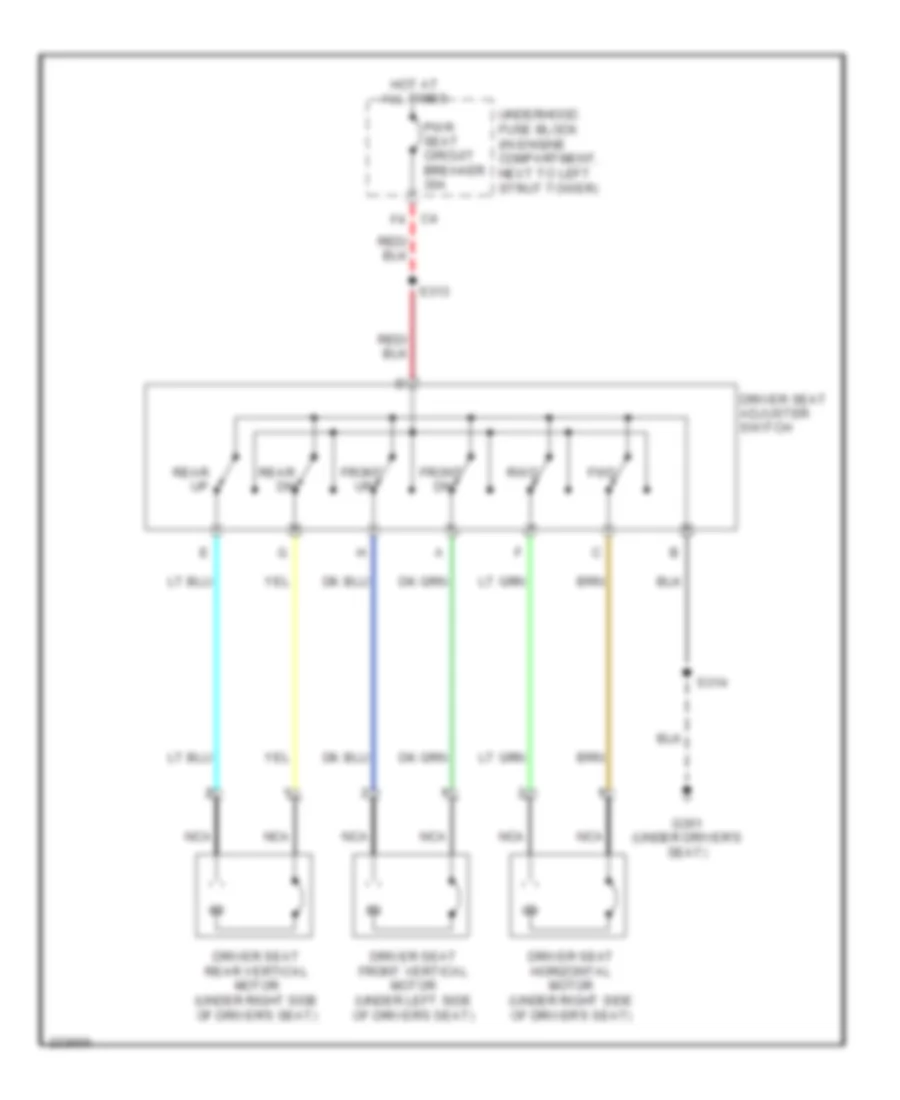
Driver Power Seat Wiring Diagram for Chevrolet HHR LS 2006
 https://portal-diagnostov.com/license.html
Automotive Electricians Portal FZCO
Automotive Electricians Portal FZCO
https://portal-diagnostov.com/license.html
https://portal-diagnostov.com/license.html
Automotive Electricians Portal FZCO
Automotive Electricians Portal FZCOList of elements for Driver Power Seat Wiring Diagram for Chevrolet HHR LS 2006:
- Driver seat adjuster switch
- Driver seat front vertical motor (under left side of driver's seat)
- Driver seat horizontal motor (under right side of driver's seat)
- Driver seat rear vertical motor (under right side of driver's seat)
- Front
- Fwd
- G301 (under driver's seat)
- Hot at all times
- Nca
- Pwr seat circuit breaker 30a
- Rear dn
- Rear up
- Rwd
- S313
- S314
- Underhood fuse block (in engine compartment, next to left strut tower)
Driver"s Lumbar Wiring Diagram for Chevrolet HHR LS 2006
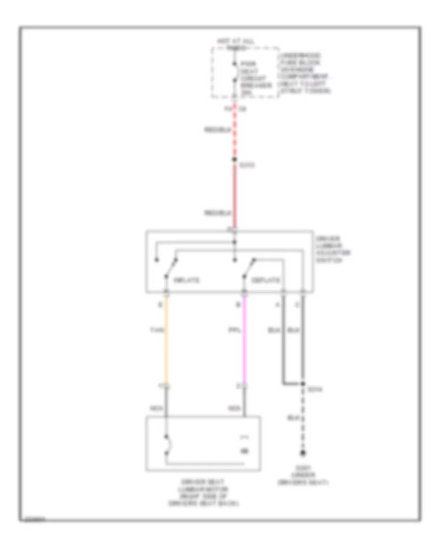 https://portal-diagnostov.com/license.html
Automotive Electricians Portal FZCO
Automotive Electricians Portal FZCO
https://portal-diagnostov.com/license.html
https://portal-diagnostov.com/license.html
Automotive Electricians Portal FZCO
Automotive Electricians Portal FZCOList of elements for Driver"s Lumbar Wiring Diagram for Chevrolet HHR LS 2006:
- Deflate
- Driver lumbar adjuster switch
- Driver seat lumbar motor (right side of driver's seat back)
- F4 c4
- G301 (under driver's seat)
- Hot at all times
- Inflate
- Nca
- Pwr seat circuit breaker 30a
- S313
- S314
- Tan
- Underhood fuse block (in engine compartment, next to left strut tower)
Heated Seats Wiring Diagram for Chevrolet HHR LS 2006
 https://portal-diagnostov.com/license.html
Automotive Electricians Portal FZCO
Automotive Electricians Portal FZCO
https://portal-diagnostov.com/license.html
https://portal-diagnostov.com/license.html
Automotive Electricians Portal FZCO
Automotive Electricians Portal FZCOList of elements for Heated Seats Wiring Diagram for Chevrolet HHR LS 2006:
- (under driver's seat)
- (under front passenger's seat)
- Acc volt
- Bck up/ htd seat fuse 10a
- Driver heated seat back element
- Driver heated seat control module (under front center of driver seat)
- Driver heated seat cushion element
- G301
- G302
- Gnd
- Heated seat fuse 20a
- Heated seat ind
- Hi temp ind ctrl
- Hi/low sig
- Hot at all times
- Hot w/ run/crank relay energized
- Hvac control module
- Ign 1 volt
- Logic
- Low temp ind ctrl
- Nca
- Passenger heated seat back element
- Passenger heated seat control module (under front center of front passenger's seat)
- Passenger heated seat cushion element
- Pnk
- S314
- S315
- Seat element sply
- Tan
- Temp sens sig
- Underhood fuse block (in engine compartment, next to left strut tower)
POWER TOP/SUNROOF
Power Top/Sunroof Wiring Diagram for Chevrolet HHR LS 2006
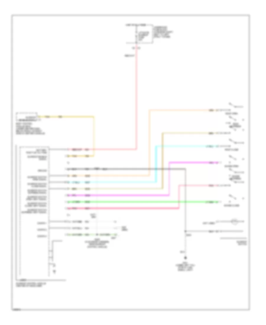 https://portal-diagnostov.com/license.html
Automotive Electricians Portal FZCO
Automotive Electricians Portal FZCO
https://portal-diagnostov.com/license.html
https://portal-diagnostov.com/license.html
Automotive Electricians Portal FZCO
Automotive Electricians Portal FZCOList of elements for Power Top/Sunroof Wiring Diagram for Chevrolet HHR LS 2006:
- (not used)
- Battery positive voltage
- Body control module (bcm) (under center dash, below radio, on right side of center console)
- C397
- C5 c2
- Config 1
- Config 2
- Config 3
- Enable signal
- G401 (under left tail/ stop & turn signal light)
- Ground
- Hot at all times
- Liftgate/ sunroof fuse 20a
- Logic
- Pnk
- Roof close
- Roof express
- Roof open
- S303
- S308
- S309 (in sunroof harness, near sunroof control module)
- Shade close
- Shade express
- Shade open
- Sunroof
- Sunroof control module (center of headliner)
- Sunroof enable signal
- Sunroof switch
- Sunroof switch close signal
- Sunroof switch close vent signal
- Sunroof switch express signal
- Sunroof switch express vent signal
- Sunroof switch open signal
- Sunroof switch open vent signal
- Tan
- Underhood fuse block (in engine compt, next to left strut tower)
POWER WINDOWS
Power Windows Wiring Diagram for Chevrolet HHR LS 2006
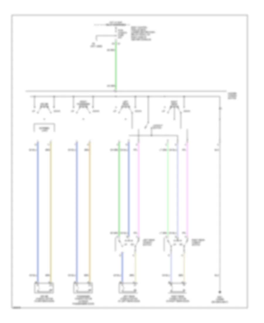 https://portal-diagnostov.com/license.html
Automotive Electricians Portal FZCO
Automotive Electricians Portal FZCO
https://portal-diagnostov.com/license.html
https://portal-diagnostov.com/license.html
Automotive Electricians Portal FZCO
Automotive Electricians Portal FZCOList of elements for Power Windows Wiring Diagram for Chevrolet HHR LS 2006:
- (not used)
- Body control module (bcm) (under center dash, below radio, on right side of center console)
- Down
- Driver switch
- Driver window motor (in driver's door)
- Express logic
- Front passenger switch
- G301 (under driver's seat)
- Hot w/ rap relay energized
- Left rear switch
- Left rear window motor (in left rear door)
- Left rear window switch
- Lockout switch
- Master window switch
- Passenger window motor (in front passenger's door)
- Pwr window fuse 30a
- Right rear switch
- Right rear window motor (in right rear door)
- Right rear window switch
RADIO
Radio Wiring Diagram, with Amplifier for Chevrolet HHR LS 2006
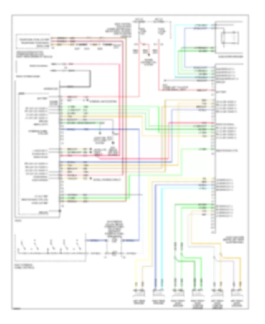 https://portal-diagnostov.com/license.html
Automotive Electricians Portal FZCO
Automotive Electricians Portal FZCO
https://portal-diagnostov.com/license.html
https://portal-diagnostov.com/license.html
Automotive Electricians Portal FZCO
Automotive Electricians Portal FZCOList of elements for Radio Wiring Diagram, with Amplifier for Chevrolet HHR LS 2006:
- (on steering column, behind steering wheel) inflatable restraint steering wheel module coil
- 10 volt ref
- Amp fuse 20a
- Antenna sig
- Audio amplifier (behind left rear quarterpanel)
- Audio common
- Bare
- Battery
- Body control module (bcm) (under center dash, below radio, on right side of center console)
- Coax
- Computer data lines system
- D10
- D11
- Dimmer sw sig
- Drain wire
- G201 (behind left end of dash)
- G401 (under left tail/stop & turn signal light)
- Ground
- Hot at all times
- Interior lights system
- L audio sig (+)
- Left front door speaker
- Left front door tweeter speaker
- Left rear speaker
- Lf lo lev audio (+)
- Lf lo lev audio (-)
- Lf low lev audio (+)
- Lf low lev audio (-)
- Lf spkr out (+)
- Lf spkr out (-)
- Logic
- Lr lo lev audio (-)
- Lr low lov audio (+)
- Lr low lov audio (-)
- Lr spkr out (+)
- Lr spkr out (-)
- Nca
- Pnk
- Power distribution system
- R audio sig (+)
- Radio
- Radio antenna base
- Radio on sig
- Radio on signal
- Rdo fuse 15a
- Remote radio ctrl
- Remote radio ctrl sig
- Rf lo lev audio (+)
- Rf lo lev audio (-)
- Rf low lov audio (+)
- Rf low lov audio (-)
- Rf spkr out (+)
- Rf spkr out (-)
- Right front door speaker
- Right front door tweeter speaker
- Right rear speaker
- Right steering wheel controls
- Rr lo lev audio (+)
- Rr lo lev audio (-)
- Rr low lov audio (+)
- Rr low lov audio (-)
- Rr spkr out (+)
- Rr spkr out (-)
- Rr sub spkr out (+)
- S201
- S205
- S318
- S407
- Satellite radio circuit
- Serial data
- Steering wheel ctrl sig
- Sub spkr out (+)
- Sub spkr out (-)
- Subwoofer speaker
- Tan
- Tan b
- Telephone voice low ref
- Telephone voice signal
- Vehicle communication interface module (vcim) (right rear corner of vehicle)
- Voice low ref
- Voice signal
Radio Wiring Diagram, without Amplifier for Chevrolet HHR LS 2006
 https://portal-diagnostov.com/license.html
Automotive Electricians Portal FZCO
Automotive Electricians Portal FZCO
https://portal-diagnostov.com/license.html
https://portal-diagnostov.com/license.html
Automotive Electricians Portal FZCO
Automotive Electricians Portal FZCOList of elements for Radio Wiring Diagram, without Amplifier for Chevrolet HHR LS 2006:
- (on steering column, behind steering wheel) inflatable restraint steering wheel module coil
- 10 volt ref
- Antenna sig
- Audio common
- Bare
- Battery
- Body control module (bcm) (under center dash, below radio, on right side of center console)
- Coax
- Computer data lines system
- D10
- Dimmer sw sig
- Drain wire
- G201 (behind left end of dash)
- Ground
- Hot at all times
- Interior lights system
- L audio sig (+)
- Left front door speaker
- Left front tweeter speaker
- Left rear door speaker
- Lf spkr out (-)
- Logic
- Lr spkr out (+)
- Lr spkr out (-)
- Nca
- Pnk
- Power distribution system
- R audio sig (+)
- Radio
- Radio antenna base
- Radio on sig
- Radio on signal
- Rdo fuse 15a
- Rf spkr out (+)
- Rf spkr out (-)
- Right front door speaker
- Right front tweeter speaker
- Right rear door speaker
- Right steering wheel controls
- Rr spkr out (+)
- Rr spkr out (-)
- S201
- S205
- S318
- S407
- Satellite radio circuit
- Serial data
- Steering wheel ctrl sig
- Tan
- Telephone voice low ref
- Telephone voice signal
- Vehicle communication interface module (vcim) (right rear corner of vehicle)
- Voice low ref
- Voice signal
Satellite Radio Wiring Diagram for Chevrolet HHR LS 2006
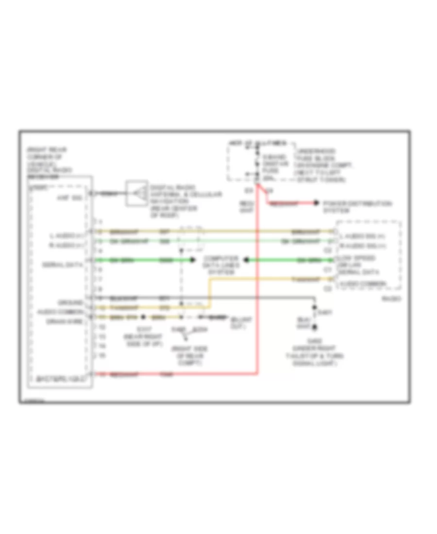 https://portal-diagnostov.com/license.html
Automotive Electricians Portal FZCO
Automotive Electricians Portal FZCO
https://portal-diagnostov.com/license.html
https://portal-diagnostov.com/license.html
Automotive Electricians Portal FZCO
Automotive Electricians Portal FZCOList of elements for Satellite Radio Wiring Diagram for Chevrolet HHR LS 2006:
- (right rear corner of vehicle) digital radio receiver
- (right side of rear compt)
- Ant sig
- Audio common
- Bare
- Battery volt
- Coax
- Computer data lines system
- Digital radio antenna, & cellular navigation (rear center of roof)
- Drain wire
- G402 (under right
- Gm lan serial data
- Ground
- Hot at all times
- L audio (+)
- L audio sig (+)
- Logic
- Low speed
- Power distribution system
- R audio (+)
- R audio sig (+)
- Radio
- S-band onstar fuse 10a
- S204
- S317 (near right side of i/p)
- S401
- S405
- Serial data
- Tail/stop & turn signal light)
- Underhood fuse block (in engine compt, next to left strut tower)
SHIFT INTERLOCK
Shift Interlock Wiring Diagram for Chevrolet HHR LS 2006
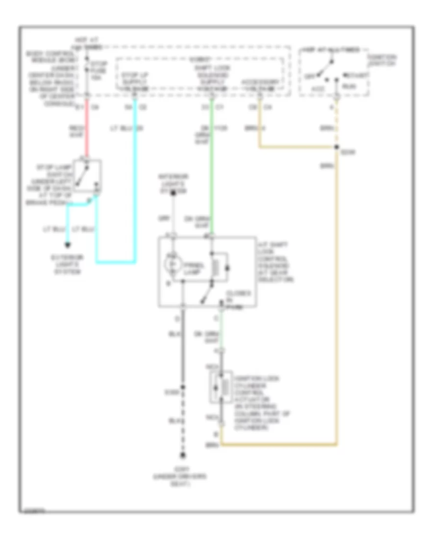 https://portal-diagnostov.com/license.html
Automotive Electricians Portal FZCO
Automotive Electricians Portal FZCO
https://portal-diagnostov.com/license.html
https://portal-diagnostov.com/license.html
Automotive Electricians Portal FZCO
Automotive Electricians Portal FZCOList of elements for Shift Interlock Wiring Diagram for Chevrolet HHR LS 2006:
- (under center dash, below radio, on right side of center console)
- (under driver's seat)
- A/t shift lock control solenoid (at gear selector)
- Acc
- Accessory voltage
- Body control module (bcm)
- C8 c4
- Closes in park
- E1 c4
- Exterior lights system
- G301
- Hot at all times
- Ignition lock cylinder control actuator (in steering column, part of ignition lock cylinder)
- Ignition switch
- Interior lights system
- Logic
- Nca
- Off
- Prndl lamp
- Run
- S206
- S300
- Start
- Stop fuse 10a
- Stop lamp switch (under left side of dash, at top of brake pedal)
STARTING/CHARGING
Charging Wiring Diagram for Chevrolet HHR LS 2006
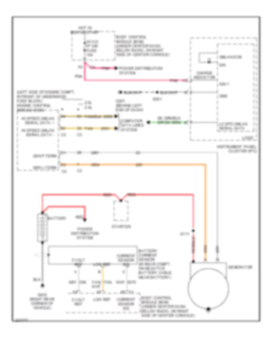 https://portal-diagnostov.com/license.html
Automotive Electricians Portal FZCO
Automotive Electricians Portal FZCO
https://portal-diagnostov.com/license.html
https://portal-diagnostov.com/license.html
Automotive Electricians Portal FZCO
Automotive Electricians Portal FZCOList of elements for Charging Wiring Diagram for Chevrolet HHR LS 2006:
- (left side of engine compt, in front of underhood fuse block) engine control module (ecm)
- 2.2l
- 2.4l
- 5 volt ref
- Battery
- Body control module (bcm) (under center dash, below radio, on right side of center console)
- Charge indicator
- Computer data lines system
- Current sensor sig
- G201 (behind left end of dash)
- G403 (right rear corner of vehicle)
- Gen f-term
- Gen l-term
- Generator
- Gmlan ecm
- Gnd
- Hi speed gmlan serial data +
- Hi speed gmlan serial data -
- Hot in run or start
- Hvac/ ip ign fuse 10a
- Ign
- Ign 1
- Instrument panel cluster (ipc)
- Lo spd gmlan serial data
- Logic
- Low ref
- Pnk
- Power distribution system
- Red
- S111
- S201
- Starter
- Tan
Starting Wiring Diagram for Chevrolet HHR LS 2006
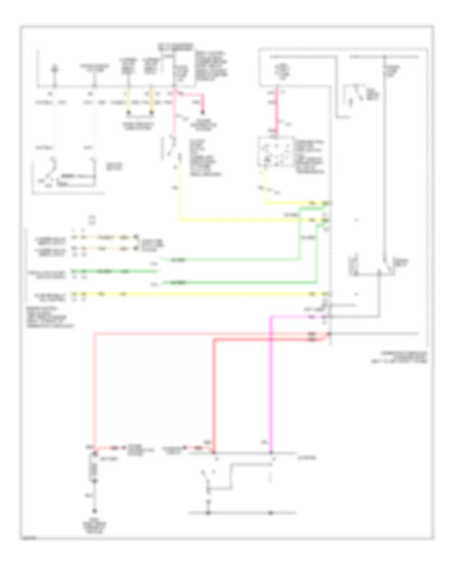 https://portal-diagnostov.com/license.html
Automotive Electricians Portal FZCO
Automotive Electricians Portal FZCO
https://portal-diagnostov.com/license.html
https://portal-diagnostov.com/license.html
Automotive Electricians Portal FZCO
Automotive Electricians Portal FZCOList of elements for Starting Wiring Diagram for Chevrolet HHR LS 2006:
- 2.2l
- 2.4l
- 5v ref
- A/t
- A10
- Acc
- Battery
- Body control module (bcm) (under center dash, below radio, on right side of center console)
- Charging circuit
- Clutch start switch (m/t) (under left side of dash, attached to clutch pedal bracket)
- Computer data lines system
- Crank fuse 30a
- Crank relay
- D d
- E6 (not used)
- Engine control module (ecm) (left side of engine compt, in front of underhood fuse block)
- G403 (right rear corner of vehicle)
- Hi speed gmlan serial data +
- Hi speed gmlan serial data -
- Hot w/ run/crank relay energized
- Hvac/ i/p ign fuse 10a
- Ignition switch
- Logic
- M/t
- Off
- Off/run/crank voltage
- Park/neutral position (pnp) switch (2.2l) (left side of engine compt, on top of transmission)
- Pnk
- Pnp/clutch start switch signal
- Power distribution system
- Prk/ neut fuse 10a
- R n
- Red
- Run
- Run/ crank relay
- Start
- Starter
- Starter relay coil control
- Tan
- Underhood fuse block (in engine compt, next to left strut tower)
SUPPLEMENTAL RESTRAINTS
Supplemental Restraints Wiring Diagram (1 of 2) for Chevrolet HHR LS 2006
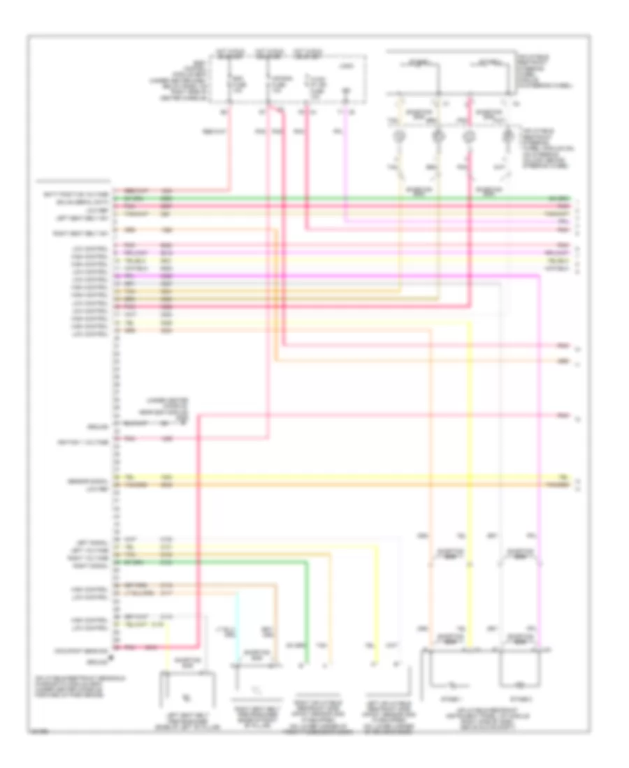 https://portal-diagnostov.com/license.html
Automotive Electricians Portal FZCO
Automotive Electricians Portal FZCO
https://portal-diagnostov.com/license.html
https://portal-diagnostov.com/license.html
Automotive Electricians Portal FZCO
Automotive Electricians Portal FZCOList of elements for Supplemental Restraints Wiring Diagram (1 of 2) for Chevrolet HHR LS 2006:
- (on lower corner of front passenger's door)
- (under center console, near sdm module) g306
- Air bag fuse 10a
- Batt positive voltage
- Body control module (bcm) (under center dash, below radio, on right side of center console)
- Gmlan serial data
- Ground
- High control
- Hot in run or start
- Hvac/ ip/ ign fuse 10a
- Ignition 1 voltage
- Ind
- Inflatable restraint instrument panel (i/p) module (right side of dash, above glove compt)
- Inflatable restraint sensing & diagnostic module (sdm) (under center console, forward of park brake)
- Inflatable restraint steering wheel module (in steering wheel)
- Inflatable restraint steering wheel module coil (on steering column, behind steering wheel)
- Left inflatable restraint side impact sensor (sis) (if equipped) (on lower corner of driver's door)
- Left seat belt pretensioner (base of left "b" pillar)
- Left seat belt sw
- Left signal
- Left voltage
- Logic
- Low control
- Low ref
- Occupant sens sig
- Pnk
- Right inflatable restraint side impact sensor (sis) (if equipped)
- Right seat belt pretensioner (base of right "b" pillar)
- Right seat belt sw
- Right signal
- Right voltage
- Sdm fuse 10a
- Sensor signal
- Shorting bar
- Stage 1
- Stage 2
- Tan
Supplemental Restraints Wiring Diagram (2 of 2) for Chevrolet HHR LS 2006
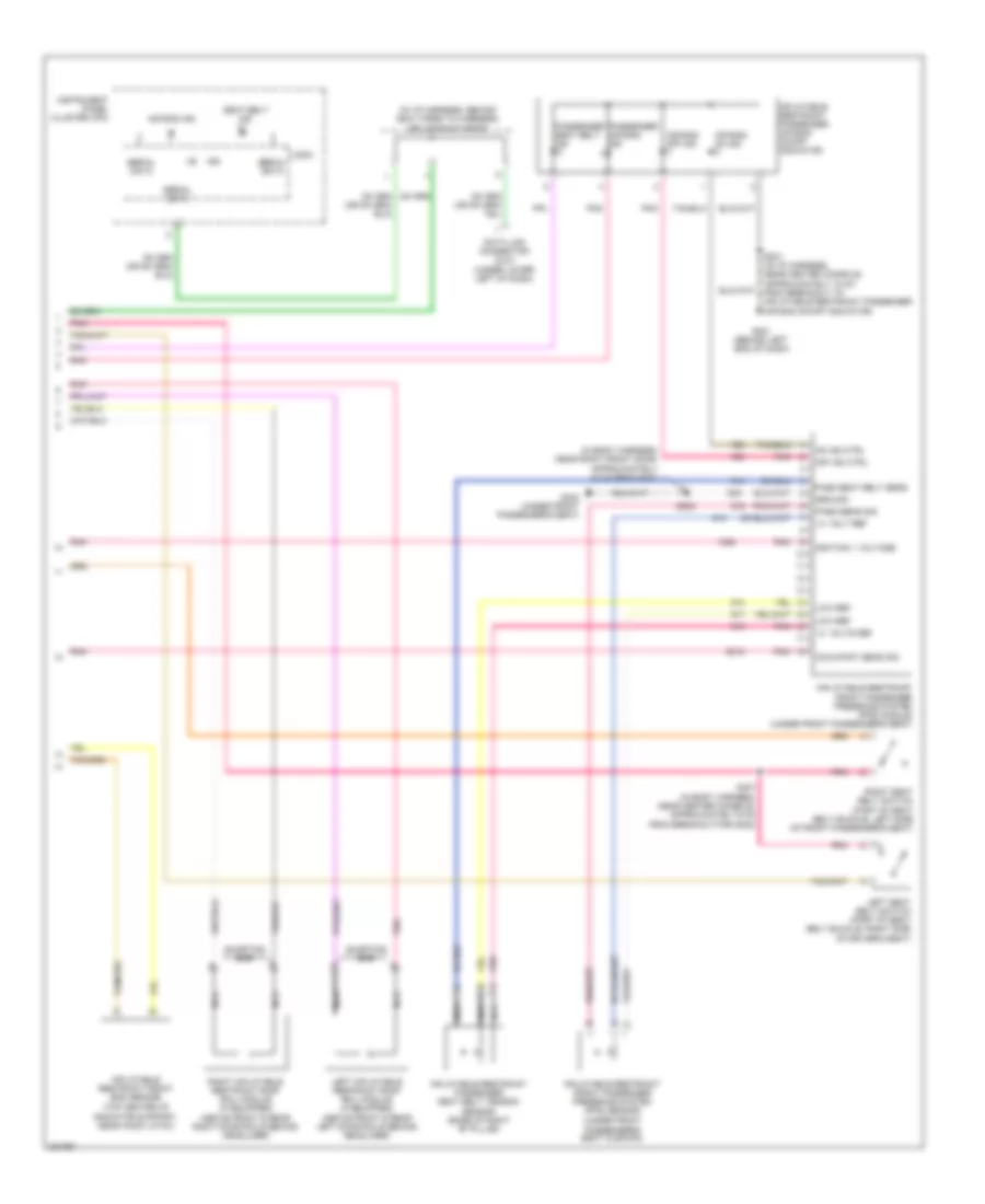 https://portal-diagnostov.com/license.html
Automotive Electricians Portal FZCO
Automotive Electricians Portal FZCO
https://portal-diagnostov.com/license.html
https://portal-diagnostov.com/license.html
Automotive Electricians Portal FZCO
Automotive Electricians Portal FZCOList of elements for Supplemental Restraints Wiring Diagram (2 of 2) for Chevrolet HHR LS 2006:
- (in body harness, near right front door, approximately 18 cm from s307)
- (in i/p harness, behind bcm taped to harness) splice pack sp205
- (top center of radiator support, near hood latch)
- 14- volt ref
- 14- volts ref
- Air bag ind
- Air bag off ind
- Air bag on ind
- Data link connector (dlc) (under lower left of dash)
- G201 (behind left end of dash)
- G302 (under front passenger's seat)
- Ground
- Ign
- Ignition 1 voltage
- Inflatable restraint front end sensor
- Inflatable restraint front passenger presence system (pps) module (under front passenger's seat)
- Inflatable restraint front passenger presence system (pps) sensor (under front
- Inflatable restraint passenger air bag on/off indicator
- Inflatable restraint passenger seat belt tension sensor (base of right "b" pillar)
- Instrument panel cluster (ipc)
- Left inflatable restraint roof rail module (if equipped) (above front & rear left door rails behind headliner)
- Left seat belt switch (part of seat belt buckle, right side of driver's seat)
- Logic
- Low ref
- Nca
- Occupant sens sig
- Off ind ctrl
- On ind ctrl
- Pass seat belt sens
- Pass sens sig
- Passenger air bag ind
- Passenger seat belt ind
- Passenger's seat cushion)
- Pnk
- Right inflatable restraint roof rail module (if equipped) (above front & rear right door rails behind headliner)
- Right seat belt switch (part of seat belt buckle, left side of front passenger's seat)
- S201 (in i/p harness, near center console, approximately 18 cm from breakout to inflatable restraint passenger air bag on/off indicator)
- S302
- S307 (in body harness, near center console, approximately 6 cm from breakout for g302)
- Seat belt ind
- Serial data
- Shorting bar
TRANSMISSION
A/T Wiring Diagram for Chevrolet HHR LS 2006
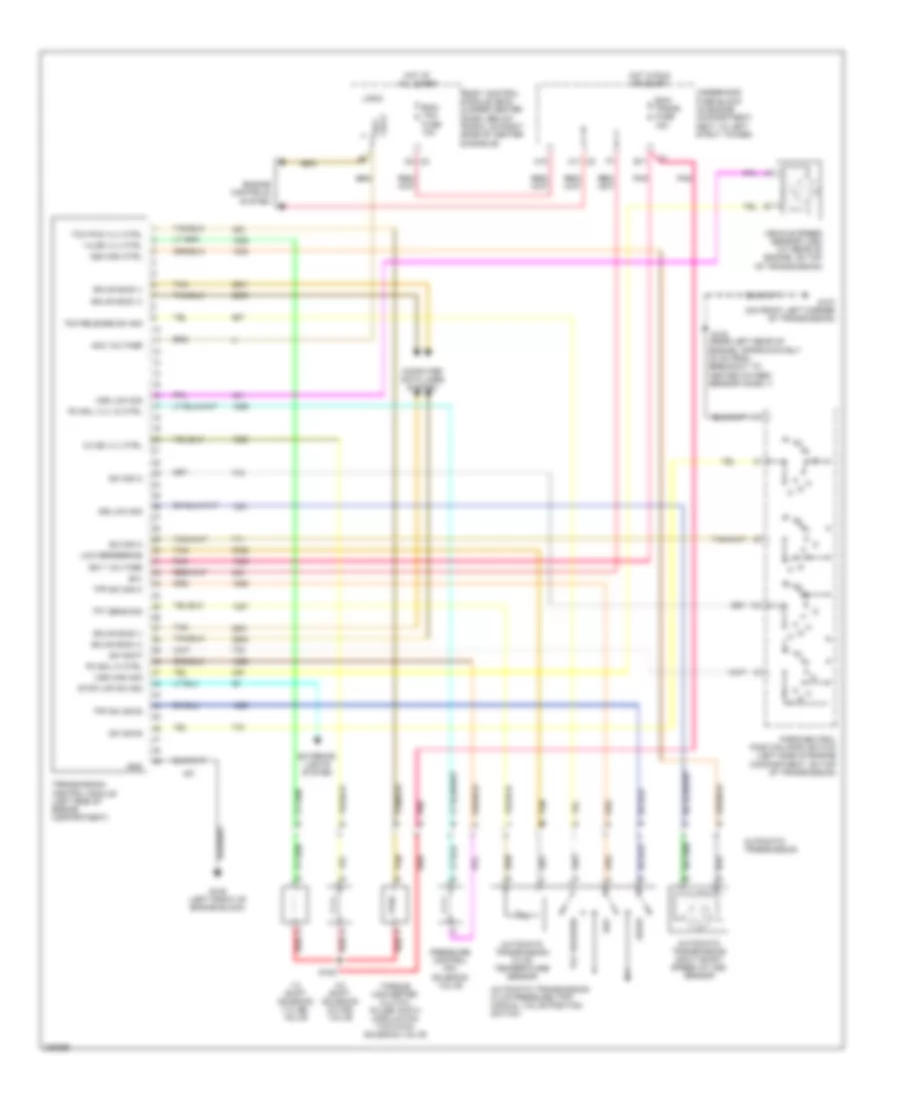 https://portal-diagnostov.com/license.html
Automotive Electricians Portal FZCO
Automotive Electricians Portal FZCO
https://portal-diagnostov.com/license.html
https://portal-diagnostov.com/license.html
Automotive Electricians Portal FZCO
Automotive Electricians Portal FZCOList of elements for A/T Wiring Diagram for Chevrolet HHR LS 2006:
- (near left rear of engine, approximately 30 cm from breakout to heated oxygen sensor (ho2s) 1)
- 1-2 shift solenoid (1-2 ss) valve
- 1-2 ss vlv ctrl
- 2-3 shift solenoid (2-3 ss) valve
- 2-3 ss vlv ctrl
- A10
- A11 c2
- Acc volt
- Acc voltage
- Automatic transmission
- Automatic transmission fluid pressure (tfp) manual valve position switch
- Automatic transmission fluid temperature sensor
- Automatic transmission input shaft speed (at iss) sensor
- B(+)
- B11
- Body control module (bcm) (under center dash, below radio, on right side of center console)
- Computer data lines system
- D4 c3
- Drive
- Ecm/ tcm fuse 10a
- Ecm/ trans fuse 15a
- Engine controls system
- Exterior lights system
- G105 (left front of engine block)
- G107 (on front left corner of transmission)
- Gmlan bus (+)
- Gmlan bus (-)
- Gnd
- Hot at all times
- Hot in run or start
- Ign 1 voltage
- Iss high ctrl
- Iss low sig
- Logic
- Low reference
- Park/neutral position (pnp) switch (left side of engine compartment, on top of transmission)
- Pc sol hi ctrl
- Pc sol vlv lo ctrl
- Pnk
- Pressure control (pc) solenoid valve
- Red
- Rev
- S103
- S108
- Stop lmp sw sig
- Sw sig a
- Sw sig b
- Sw sig c
- Sw sig p
- Tan
- Tcc pwm vlv ctrl
- Tcc release
- Tcc release sw sig
- Tfp sw sig b
- Tfp sw sig c
- Tft sens sig
- Torque converter clutch pulse width modulation (tcc pwm) solenoid valve
- Transmission control module (left side of engine compartment)
- Underhood fuse block (in engine compartment, next to left strut tower)
- Vehicle speed sensor (vss) (at rear of engine, on top of transmission)
- Vss high sig
- Vss low sig
M/T Wiring Diagram for Chevrolet HHR LS 2006
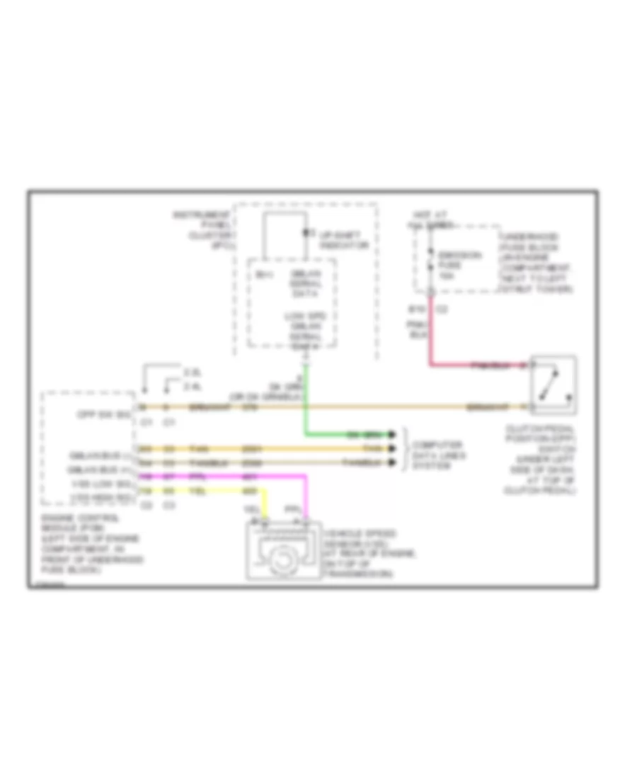 https://portal-diagnostov.com/license.html
Automotive Electricians Portal FZCO
Automotive Electricians Portal FZCO
https://portal-diagnostov.com/license.html
https://portal-diagnostov.com/license.html
Automotive Electricians Portal FZCO
Automotive Electricians Portal FZCOList of elements for M/T Wiring Diagram for Chevrolet HHR LS 2006:
- 2.2l
- 2.4l
- B(+)
- C2 b10
- Clutch pedal position (cpp) switch (under left side of dash, at top of clutch pedal)
- Computer data lines system
- Cpp sw sig
- Emission fuse 10a
- Engine control module (pcm) (left side of engine compartment, in front of underhood fuse block)
- Gmlan bus (+)
- Gmlan bus (-)
- Gmlan serial data
- Hot at all times
- Instrument panel cluster (ipc)
- Low spd gmlan serial data
- Tan
- Underhood fuse block (in engine compartment, next to left strut tower)
- Up-shift indicator
- Vehicle speed sensor (vss) (at rear of engine, on top of transmission)
- Vss high sig
- Vss low sig
TRUNK, TAILGATE, FUEL DOOR
Liftgate Release Wiring Diagram for Chevrolet HHR LS 2006
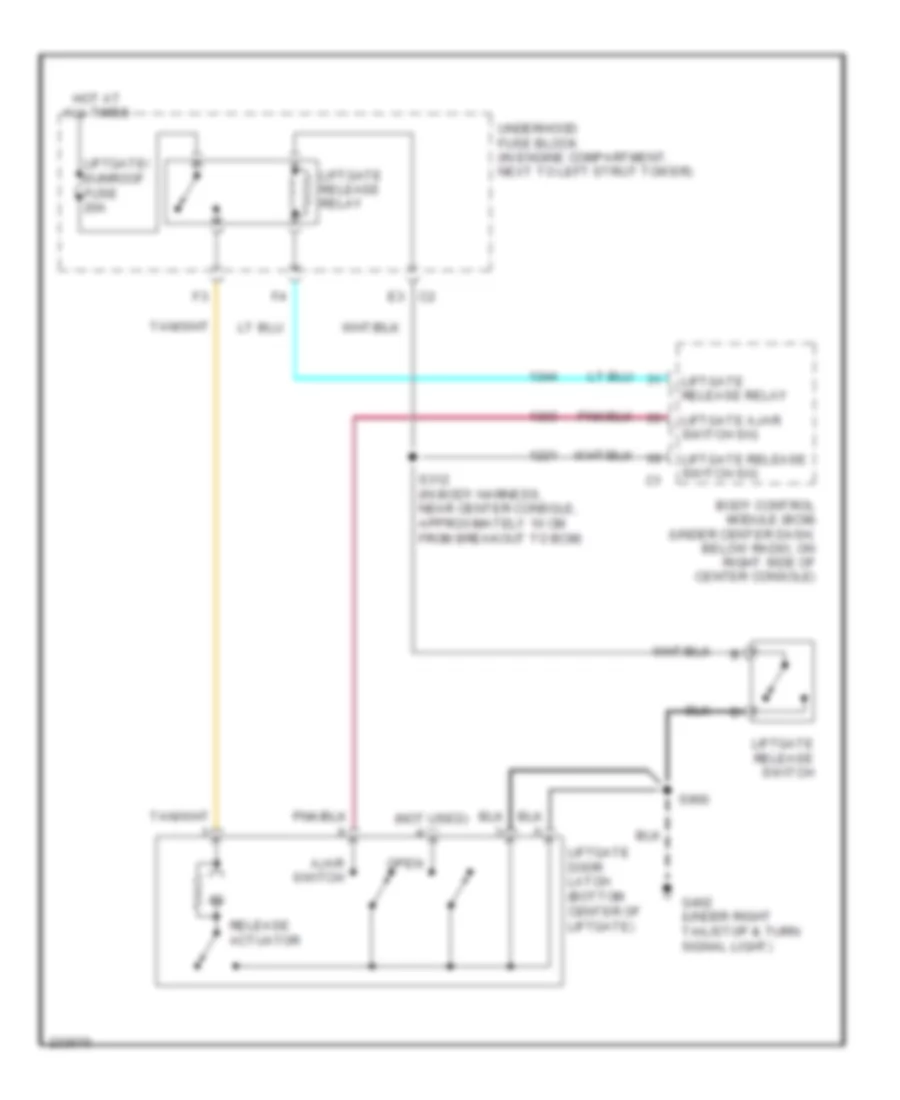 https://portal-diagnostov.com/license.html
Automotive Electricians Portal FZCO
Automotive Electricians Portal FZCO
https://portal-diagnostov.com/license.html
https://portal-diagnostov.com/license.html
Automotive Electricians Portal FZCO
Automotive Electricians Portal FZCOList of elements for Liftgate Release Wiring Diagram for Chevrolet HHR LS 2006:
- (not used)
- Ajar switch
- Body control module (bcm) (under center dash, below radio, on right side of center console)
- G402 (under right tail/stop & turn signal light)
- Hot at all times
- Liftgate ajar switch sig
- Liftgate door latch (bottom center of liftgate)
- Liftgate release relay
- Liftgate release switch
- Liftgate release switch sig
- Liftgate/ sunroof fuse 20a
- Open
- Release actuator
- S312 (in body harness, near center console, approximately 10 cm from breakout to bcm)
- S900
- Underhood fuse block (in engine compartment, next to left strut tower)
WARNING SYSTEMS
Warning Systems Wiring Diagram for Chevrolet HHR LS 2006
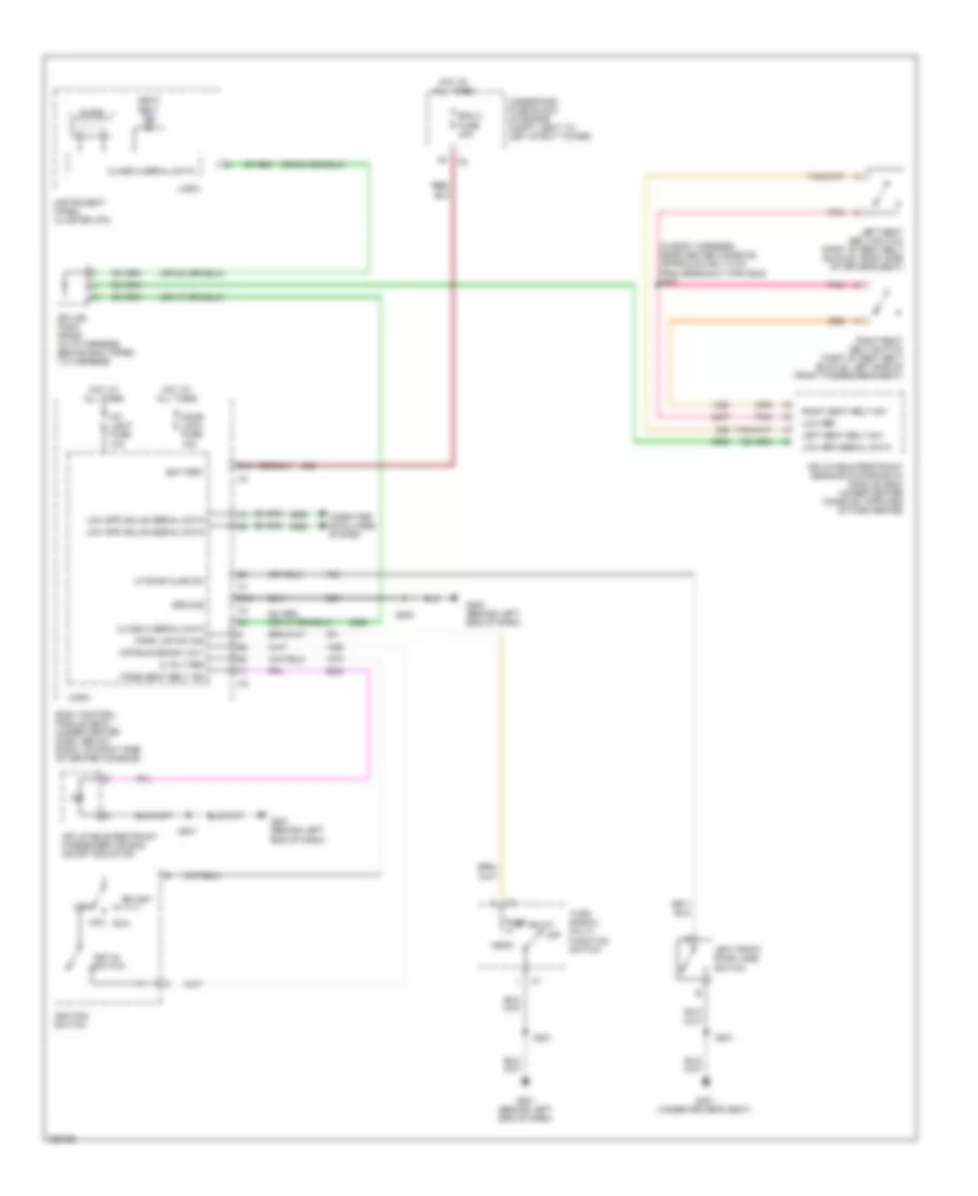 https://portal-diagnostov.com/license.html
Automotive Electricians Portal FZCO
Automotive Electricians Portal FZCO
https://portal-diagnostov.com/license.html
https://portal-diagnostov.com/license.html
Automotive Electricians Portal FZCO
Automotive Electricians Portal FZCOList of elements for Warning Systems Wiring Diagram for Chevrolet HHR LS 2006:
- (in body harness, near center console, approximately 6 cm from breakout for g302) s307
- 5 volt ref
- Acc
- Auto
- Battery
- Bcm 2 fuse 40a
- Body control module (bcm) (under center dash, below radio, on right side of center console)
- Chime
- Class 2 serial data
- Computer data lines system
- D12
- Door lock fuse 15a
- E12
- G201 (behind left end of dash)
- G203 (behind left end of dash)
- G301 (under driver's seat)
- Ground
- Head
- Hot at all times
- Ignition switch
- Inflatable restraint passenger air bag on/off indicator
- Inflatable restraint sensing & diagnostic module (sdm) (under center console, forward of park brake)
- Instrument panel cluster (ipc)
- Int light fuse 10a
- Key-in switch
- Left front door jamb switch
- Left seat belt sw
- Left seat belt switch (part of seat belt buckle, right side of driver's seat)
- Lf door ajar sw
- Logic
- Low ref
- Low spd gmlan serial data
- Low spd serial data
- Off
- Off/run/crank volt
- Park
- Park lmp sw sig
- Pass seat belt ind
- Pnk
- Right seat belt sw
- Right seat belt switch (part of seat belt buckle, left side of front passenger's seat)
- Run
- S200
- S201
- S301
- Seat belt ind
- Splice pack sp205 (in i/p harness, behind bcm taped to harness)
- Start
- Turn signal/ multi- function switch
- Underhood fuse block (in engine compt, next to left strut tower)
WIPER/WASHER
Front Wiper/Washer Wiring Diagram for Chevrolet HHR LS 2006
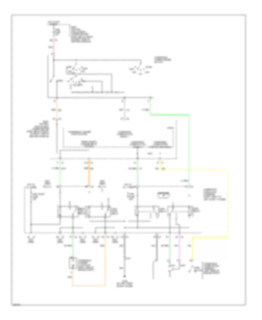 https://portal-diagnostov.com/license.html
Automotive Electricians Portal FZCO
Automotive Electricians Portal FZCO
https://portal-diagnostov.com/license.html
https://portal-diagnostov.com/license.html
Automotive Electricians Portal FZCO
Automotive Electricians Portal FZCOList of elements for Front Wiper/Washer Wiring Diagram for Chevrolet HHR LS 2006:
- (not used)
- A6 c2
- A7 c2
- Body control module (bcm) (under center dash, below radio, on right side of center console)
- C12 c3
- C4 e6
- C5 c3
- E1 c4
- F9 c2
- G109 (on left front shock tower)
- High
- Hot at all times
- Hot in acc or run
- Int
- Logic
- Low
- Mist
- Off
- Park switch
- Pnk
- Rear window washer relay control
- Rear wsw relay
- S101
- Underhood fuse block (in engine compt, next to left strut tower)
- Wash
- Windshield washer fluid pump (right side of engine compt)
- Windshield washer pump control
- Windshield wiper motor assembly (left rear of engine compt)
- Windshield wiper motor park switch signal
- Windshield wiper switch signal 1
- Windshield wiper switch signal 2
- Windshield wiper/washer switch
- Wpr diode
- Wpr fuse 10a
- Wpr fuse 25a
- Wpr relay
- Wsw pump fuse 15a
- Wsw pump relay
Rear Wiper/Washer Wiring Diagram for Chevrolet HHR LS 2006
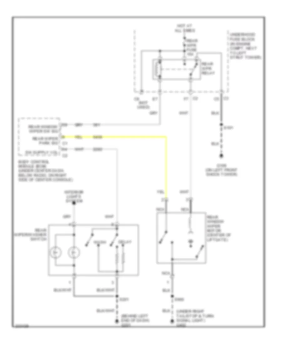 https://portal-diagnostov.com/license.html
Automotive Electricians Portal FZCO
Automotive Electricians Portal FZCO
https://portal-diagnostov.com/license.html
https://portal-diagnostov.com/license.html
Automotive Electricians Portal FZCO
Automotive Electricians Portal FZCOList of elements for Rear Wiper/Washer Wiring Diagram for Chevrolet HHR LS 2006:
- (behind left end of dash) g201
- (not used)
- (under right tail/stop & turn signal light) g402
- Body control module (bcm) (under center dash, below radio, on right side of center console)
- C2 f7
- C3 c5
- Delay
- G109 (on left front shock tower)
- Hot at all times
- Interior lights system
- Nca
- Rear window wiper motor (center of liftgate)
- Rear window wiper sw sig
- Rear wiper park sig c1
- Rear wiper/washer switch
- Rear wpr fuse 15a
- Rear wpr relay
- S101
- S201
- S900
- Underhood fuse block (in engine compt, next to left strut tower)
- Wash

 Čeština
 Dansk
Dansk Deutsch
 Ελληνικά
 English
 English
 Español
 Suomi
Suomi Français
 Français
 עברית
עברית Hrvatski
 Magyar
 Italiano
 日本語
日本語 한국어
한국어 Nederlands
 Polski
 Português
 Português
 Română
 Русский
 Slovenčina
 Slovenščina
 Svenska
 Türkçe
