AIR CONDITIONING
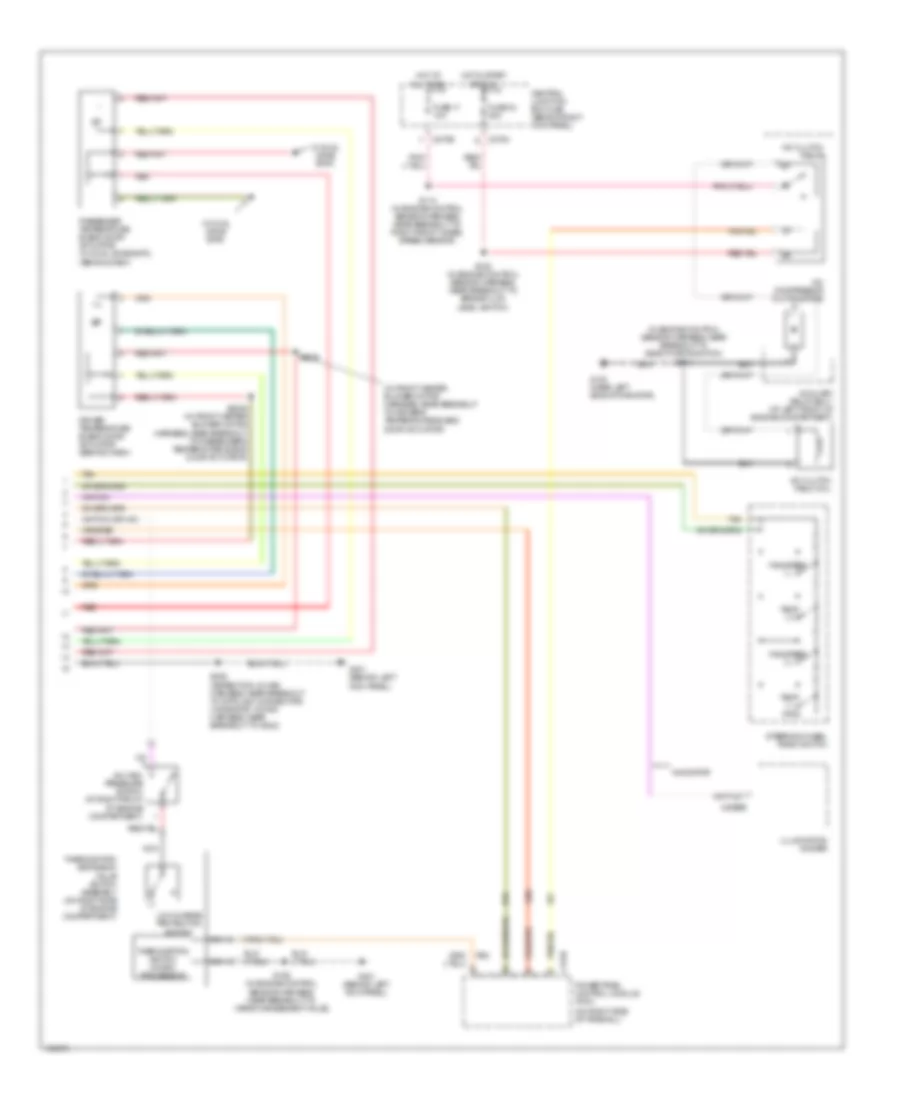
Automatic A/C Wiring Diagram (1 of 2) for Ford Expedition 2003
 https://portal-diagnostov.com/license.html
Automotive Electricians Portal FZCO
Automotive Electricians Portal FZCO
https://portal-diagnostov.com/license.html
https://portal-diagnostov.com/license.html
Automotive Electricians Portal FZCO
Automotive Electricians Portal FZCO
List of elements for Automatic A/C Wiring Diagram (1 of 2) for Ford Expedition 2003:
- (behind left kick panel) g301
- (behind right kick panel) g200
- (expedition: near breakout to dlc) (navigator: near breakout to g202) s208
- (expedition: near breakout to electronic automatic temperature control module) (navigator: near breakout to central junction box)
- (in main harness, near breakout to glove box lamp)
- (in main harness, near breakout to illumination dimmer)
- (in main harness, near breakout to instrument cluster) s264
- (in main harness, near breakout to instrument cluster) s277
- +/-
- Air bag sliding contact
- Ambient air temperature sensor (behind radiator grille)
- Auxiliary air conditioner heater
- C2113b
- C228a
- C228b
- C270e
- C270g
- Central junction box (cjb) (behind right kick panel)
- Cruise control system
- Data link connector (dlc) (under left side of dash)
- Defogger system
- Electronic automatic temperature control (eatc) module (in center of dash)
- Front blower motor relay
- Fuse 116 40a
- Fuse 13 10a
- Fuse 5 7.5a
- G200 (behind left kick panel)
- Heater blower control module (behind dash)
- Heater blower motor (behind dash)
- Hot at all times
- Hot in run
- In-vehicle temperature sensor
- In-vehicle temperature/ humidity sensor (navigator: in center of dash) (expedition: in left side of dash
- Interior lights system
- Microprocessor
- Navigator
- Nca
- Pwr
- Red
- Remote solenoid assembly (behind center of dash)
- S2019
- S203
- S203 (in main harness, near breakout to glove box lamp)
- S241
- Sig rtn-
- Sunload sensor (on top center of dash, near windshield)
- Tan
- Vbatt
- Vehicle security module (vsm) (under right side of dash)
- Vpwr
- Vref
- W/ dual zone eatc
- W/ single zone eatc
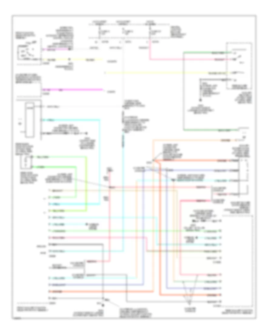
Automatic A/C Wiring Diagram (2 of 2) for Ford Expedition 2003
 https://portal-diagnostov.com/license.html
Automotive Electricians Portal FZCO
Automotive Electricians Portal FZCO
https://portal-diagnostov.com/license.html
https://portal-diagnostov.com/license.html
Automotive Electricians Portal FZCO
Automotive Electricians Portal FZCOList of elements for Automatic A/C Wiring Diagram (2 of 2) for Ford Expedition 2003:
- (behind dash)
- (in engine control sensor harness, near breakout to deactivator switch) s104
- (in front heater blower motor harness, near breakout to driver's temperature blend door actuator)
- (on right side of firewall)
- A/c clutch field coil
- A/c clutch relay
- A/c compressor clutch diode
- A/c high pressure switch (at right front of engine compartment)
- Auxiliary relay box 1 (at left front of engine compartment)
- C175b
- C2065b
- C270a
- C270b
- Central junction box (cjb) (behind right kick panel)
- Driver temperature blend door actuator (behind dash)
- Fan speed (+)
- Fan speed (-)
- Fuse 11 10a
- Fuse 33 20a
- G100 (near left side of radiator)
- G301 (behind left kick panel)
- Hot at all times
- Hot in start or run
- Illumination dimmer
- Low charge protection switch
- Navigator
- Nca
- Passenger temperature blend door actuator (w/ dual zone eatc)
- Powertrain control module (pcm)
- Red
- S105 (in engine control sensor harness, near breakout to brake fluid level switch)
- S106 (in engine control sensor harness, near breakout to vapor management valve)
- S113 (in engine control sensor harness, near breakout to right front wheel speed sensor)
- S2025 (in front heater blower motor harness, near breakout to passenger's temperature blend door actuator)
- S2026
- S208 (expedition: in main harness, near breakout to data link connector) (navigator: in main harness, near breakout to g202)
- Steering wheel radio switch
- Tan
- Temp (+)
- Temp (-)
- Thermostatic expansion value switch assembly (on right side of engine compartment)
- Thermostatic switch (micro- processor)
- W/ dual zone eatc
Auxiliary Heater-A/C Wiring Diagram for Ford Expedition 2003
 https://portal-diagnostov.com/license.html
Automotive Electricians Portal FZCO
Automotive Electricians Portal FZCO
https://portal-diagnostov.com/license.html
https://portal-diagnostov.com/license.html
Automotive Electricians Portal FZCO
Automotive Electricians Portal FZCOList of elements for Auxiliary Heater-A/C Wiring Diagram for Ford Expedition 2003:
- (expedition: near breakout
- (in body main harness, near breakout to c800) s319
- (in center of dash) electronic automatic temperature control (eatc) module
- (in console panel harness, near breakout to console 1 power point) s205
- (in interior illumination harness, near breakout to front auxiliary function selector switch assembly)
- (in interior illumination harness, near breakout to front auxiliary function selector switch assembly) s903
- (in rear lamp conn harn near breakout to rear blend door actuator)
- (in rear lamp connector harness, near breakout to auxiliary blower motor resistor assembly)
- (in rear lamp connector harness, near breakout to c410) s424
- (in rear lamp connector harness, near breakout to rear blend door actuator)
- (navigator: near breakout to
- (near breakout to c210)
- (not used)
- (on left ``b" pillar,
- +/-
- Auxiliary blower motor (at right side of cargo area, behind trim)
- Auxiliary blower motor resistor assembly (at right side of cargo area, behind trim)
- Auxiliary relay box 2 (at right side of cargo area, behind trim)
- Behind trim)
- C228b
- C270e
- C270j
- C270n
- C294b
- C3198a
- C3198b
- C989a
- C989b
- Central junction box (cjb) (behind right kick panel)
- Central junction box) s241
- Def
- Floor
- Front auxiliary function selector switch assembly
- Front function selector switch assembly
- Fuse 107 30a
- Fuse 13 10a
- Fuse 18 10a
- G300
- G404 (on right side of luggage compartment, behind trim)
- Ground
- Hot at all times
- Hot in start or run
- Interior lights system
- Max
- Mix
- Nca
- Near breakout to c410)
- Norm
- Off
- Rear auxiliary function selector switch assembly
- Rear blend door actuator (at right side of cargo area, behind trim)
- Rear blower motor relay
- Rear mode door actuator (at right side of cargo area, behind trim)
- Red/ pnk
- Red/pnk
- S230
- S412
- S423
- S431
- S432
- S904
- To electronic automatic temperature control module)
- Vent
- Vpwr
- W/ center console
- W/ eatc
- W/o center console
- W/o eatc
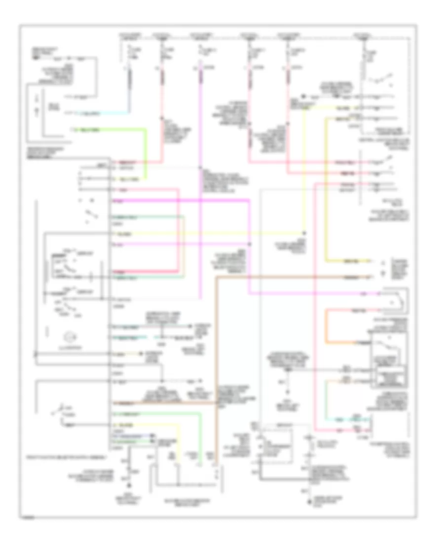
Manual A/C Wiring Diagram for Ford Expedition 2003
 https://portal-diagnostov.com/license.html
Automotive Electricians Portal FZCO
Automotive Electricians Portal FZCO
https://portal-diagnostov.com/license.html
https://portal-diagnostov.com/license.html
Automotive Electricians Portal FZCO
Automotive Electricians Portal FZCOList of elements for Manual A/C Wiring Diagram for Ford Expedition 2003:
- (behind right kick panel) g200
- (expendition: near breakout to data link connector)
- (in engine control sensor harness, near breakout to vapor management valve) s106
- (in front heater blower motor harness, in breakout to c237)
- (in front heater blower motor harness, in breakout to heater blower motor) s291
- (in main harness, near breakout to glove box lamp) s203
- (near left side of radiator) g100
- A/c clutch field coil
- A/c clutch relay
- A/c compressor clutch diode
- A/c high pressure switch (at right front of engine compartment)
- Auxiliary relay box 1 (at left front of engine compartment)
- Blower motor resistor (behind dash)
- C175b
- C270a
- C270b
- C270e
- C270g
- C294a
- C294b
- C294c
- Central junction box (cjb) (behind right kick panel)
- Defogger system
- Defrost
- Exterior lights system
- Floor
- Front blower motor relay
- Front function selector switch assembly
- Fuse 10a
- Fuse 11 10a
- Fuse 13 10a
- Fuse 33 20a
- Fuse 40a
- Fuse 7.5a
- G200 (behind right kick panel)
- G301 (behind left kick panel)
- Heater blower motor (behind dash)
- Hot at all times
- Hot in start or run
- Illumination
- Interior lights system
- Low charge protection switch
- Max
- Mix
- Nca
- Norm
- Off
- Pnk
- Powertrain control module (pcm) (on right side of firewall)
- S105 (in engine control sensor harness, near breakout to brake fluid level switch)
- S200
- S200 (in front heater blower motor harness, in breakout to c237)
- S202 (in main harness, near breakout to instrument cluster)
- S208
- S230 (in main harness, near breakout to c210)
- S241 (expendition: in main harness, near breakout to electronic automatic temperature control module)
- S262 (in main harness, near breakout to front function selector switch assembly)
- S277 (in main harness, near breakout to instrument cluster)
- Sensor harness, near breakout to deactivator switch) s104
- Solid state
- Temperature blend door actuator (behind dash)
- Thermostatic expansion valve switch assembly (on right side of engine compartment)
- Thermostatic switch (micro- processor)
- Vbatt
- Vent
ANTI-LOCK BRAKES
Anti-lock Brakes Wiring Diagram for Ford Expedition 2003
 https://portal-diagnostov.com/license.html
Automotive Electricians Portal FZCO
Automotive Electricians Portal FZCO
https://portal-diagnostov.com/license.html
https://portal-diagnostov.com/license.html
Automotive Electricians Portal FZCO
Automotive Electricians Portal FZCOList of elements for Anti-lock Brakes Wiring Diagram for Ford Expedition 2003:
- (expedition)
- (expedition) (navigator)
- (in body main harness, near breakout to c214)
- (in main harness, in breakout to c210)
- (navigator)
- (near left side of radiator) g100
- - sig rtn
- Abs control module (at left side of engine compt)
- Auxiliary relay box 1 (w/ ivd) (at left front of engine compt)
- Brake booster sensor (w/ ivd) (at left rear of engine compt)
- Brake fluid level switch (in brake fluid reservoir, near firewall)
- Brake pedal position switch (on brake pedal support)
- C2188c
- C270b
- C270c
- C270d
- C270e
- C270f
- C3184b
- Central junction box (cjb) (behind right kick panel)
- Computer data lines system
- Exterior lights system
- Four-wheel drive control module (at left "b" pillar)
- Fuse 10a
- Fuse 20a
- Fuse 30a
- Fuse 5a
- Fuse 7.5a
- G100 (near left side of radiator)
- G200 (navigator) (behind right kick panel)
- G300 (expedition) on left "b" pillar, behind trim)
- Gnd
- Hot at all times
- Hot in start or run
- Illum
- Ind
- Interior lights system
- Iso
- Ivd stop lamp relay
- Left front wheel speed sensor
- Left rear wheel speed sensor
- Nca
- On/ off
- Primary brake pressure sensor (w/ ivd) (at left rear of engine compt, on brake master cylinder)
- Radio (w/ ivd)
- Red
- Red/ pnk
- Red/pnk
- Right front wheel speed sensor
- Right rear wheel speed sensor
- S101
- S104
- S123
- S2003 (in main harness, near breakout to brake pedal position switch)
- S202
- S205
- S277
- S281
- S373
- S387 s282
- Scp +
- Scp -
- Secondary brake pressure sensor (w/ ivd) (at left rear of engine compt, on brake master cylinder booster)
- Steering position sensor (w/ ivd) (on steering column)
- Tan/ red
- Tan/red
- Traction control switch (w/ ivd)
- Trailer electronic brake control connector (w/ ivd) (behind center of dash)
- Vbatt
- Vpwr
- Vref
- Yaw velocity sensor (w/ ivd) (under center console)
ANTI-THEFT
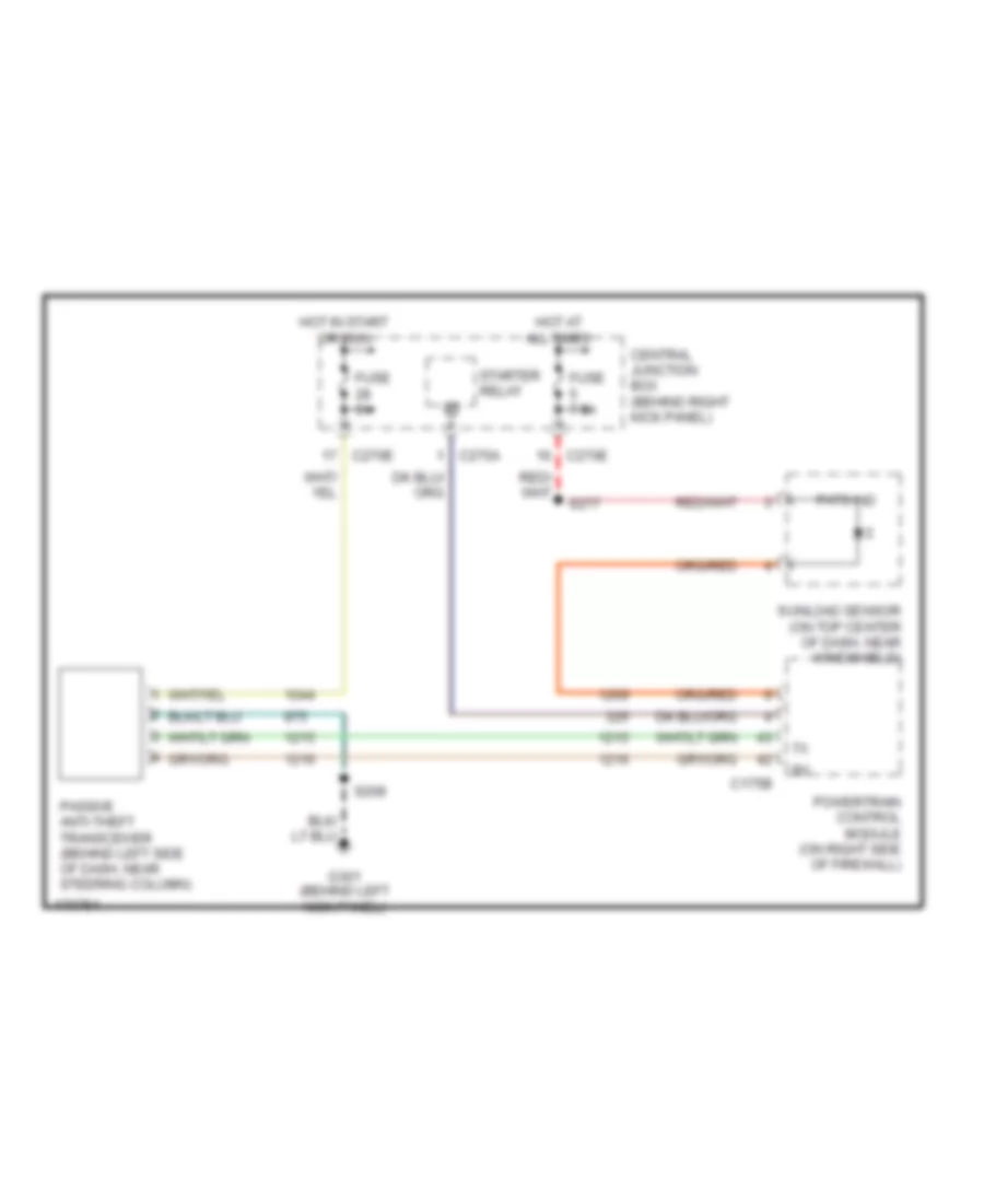
Passive Anti-theft Wiring Diagram for Ford Expedition 2003
 https://portal-diagnostov.com/license.html
Automotive Electricians Portal FZCO
Automotive Electricians Portal FZCO
https://portal-diagnostov.com/license.html
https://portal-diagnostov.com/license.html
Automotive Electricians Portal FZCO
Automotive Electricians Portal FZCOList of elements for Passive Anti-theft Wiring Diagram for Ford Expedition 2003:
- C175b
- C270a
- C270e
- Central junction box (behind right kick panel)
- Fuse 5a
- Fuse 7.5a
- G301 (behind left kick panel)
- Hot at all times
- Hot in start or run
- Passive anti-theft transceiver (behind left side of dash, near steering column)
- Pats ind
- Powertrain control module (on right side of firewall)
- S208
- S277
- Starter relay
- Sunload sensor (on top center of dash, near windshield)
Power Door Locks Wiring Diagram for Ford Expedition 2003
 https://portal-diagnostov.com/license.html
Automotive Electricians Portal FZCO
Automotive Electricians Portal FZCO
https://portal-diagnostov.com/license.html
https://portal-diagnostov.com/license.html
Automotive Electricians Portal FZCO
Automotive Electricians Portal FZCOList of elements for Power Door Locks Wiring Diagram for Ford Expedition 2003:
- (behind right kick panel) g201
- (expedition) (navigator)
- (in body main harness, near breakout to c214) s359
- (navigator) (expedition)
- (near breakout to g201)
- (near breakout to left ``c" pillar safety canopy sensor) s313
- (near breakout to liftgate glass actuator) s465
- (on left ``b" pillar, behind trim) g300
- 1/2
- 3/4
- 5/6
- 7/8
- 9/0
- A/c system
- C2113a
- C2113b
- C2113c
- C270d
- C270f
- C270h
- C270j
- Central junction box (cjb) (behind right kick panel)
- Computer data lines system
- Door lock relay
- Driver door unlock relay
- Driver side door lock switch
- Driver side rear door ajar switch
- Exterior lights
- Fuse 15a
- Fuse 20a
- Fuse 30a
- Fuse 7.5a
- G201 (behind right kick panel)
- G300 (on left ``b" pillar, behind trim)
- G402 (on left side of luggage compartment, behind trim)
- Headlamp relay
- Headlights system
- Horns system
- Hot at all times
- Illumination
- Interior lights system
- Key pad switch assembly
- Left front door ajar switch
- Left front door lock actuator
- Left rear door lock actuator
- Liftgate ajar switch
- Liftgate glass actuator
- Liftgate glass release relay
- Liftgate glass release switch
- Liftgate lock actuator
- Lock
- Microprocessor
- Navigator
- Nca
- Park lamp relay
- Passenger side door lock switch
- Passenger side rear door ajar switch
- Power windows system
- Red
- Red/ pnk
- Right front door ajar switch
- Right front door lock actuator
- Right rear door lock actuator
- S203 (exp) s392 (nav)
- S212
- S314 (near breakout to c327)
- S343 (near breakout to g201)
- S344
- S356
- S358
- S379
- S391
- S402
- S402 s415
- S501
- S506
- S600
- S700
- S800
- Seats system
- System
- Tan
- Trunk, tailgate, fuel doors system
- Unlock
- Vehicle security module (vsm) (under right side of dash)
- W/ power liftgate
- W/o power liftgate
- Wiper/ washer system
COMPUTER DATA LINES
Computer Data Lines Wiring Diagram for Ford Expedition 2003
 https://portal-diagnostov.com/license.html
Automotive Electricians Portal FZCO
Automotive Electricians Portal FZCO
https://portal-diagnostov.com/license.html
https://portal-diagnostov.com/license.html
Automotive Electricians Portal FZCO
Automotive Electricians Portal FZCOList of elements for Computer Data Lines Wiring Diagram for Ford Expedition 2003:
- (behind right kick panel) g200
- (in main harn, in breakout to c213) s229
- (in main harness, near breakout to sunload sensor) s285
- (near breakout to driver's side climate controlled seat module) s386
- (near breakout to g301) s349
- (near breakout to instrument cluster) s264
- (under left side of dash)
- Abs control module (left side of engine compt)
- C175b
- C2113c
- C2188d
- C220a
- C228b
- C270h
- C290b
- C3031b
- C3036b
- C310a
- C3184b
- C341c
- C349a
- C4014b
- Cd changer
- Central junction box (cjb) (behind right kick panel)
- Data link connector
- Driver seat module (under driver's seat)
- Driver side climate controlled seat module (under driver's seat)
- Dvd player
- Electronic automatic temperature control module (in center of dash)
- Four-wheel drive control module (at left "b" pillar)
- Fuse 20a
- G102 (on right rear of engine compt)
- Hot at all times
- Instrument cluster
- Low tire pressure module (at left "c" pillar)
- Parking aid module (at left side of cargo area, behind trim)
- Passenger side climate controlled seat module (under passenger's seat)
- Powertrain control module (on right side of firewall)
- Radio
- Rear integrated control panel (ricp)
- Restraints control module (below center console)
- S110 (near breakout to thermostatic expansion valve switch assembly)
- S111 (near breakout to thermostatic expansion valve switch assembly)
- S2005
- S2007 (near breakout to data link connector)
- S2008 (near breakout to data link connector)
- S202
- S306 (near breakout to console 2 power point)
- Sunload sensor)
- Tan
- Tan (in console panel harness, near breakout to c314) s323
- Vehicle security module (under right side of dash)
- W/ navigation system
- W/o navigation system
COOLING FAN
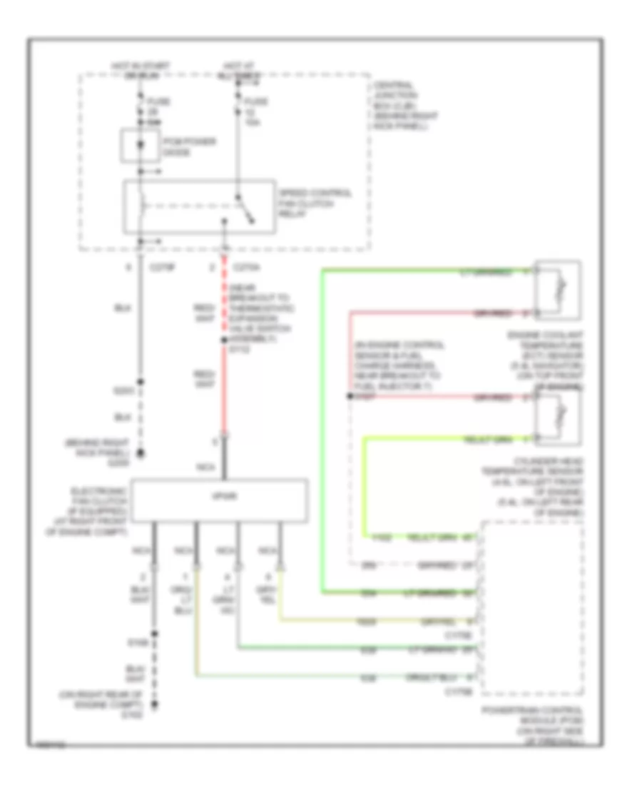
Cooling Fan Wiring Diagram for Ford Expedition 2003
 https://portal-diagnostov.com/license.html
Automotive Electricians Portal FZCO
Automotive Electricians Portal FZCO
https://portal-diagnostov.com/license.html
https://portal-diagnostov.com/license.html
Automotive Electricians Portal FZCO
Automotive Electricians Portal FZCOList of elements for Cooling Fan Wiring Diagram for Ford Expedition 2003:
- (behind right kick panel) g200
- (in engine control sensor & fuel charge harness, near breakout to fuel injector 7) s127
- (near breakout to thermostatic expansion valve switch assembly) s112
- (on right rear of engine compt) g102
- C175b
- C175e
- C270a
- C270f
- Central junction box (cjb) (behind right kick panel)
- Cylinder head temperature sensor (4.6l: on left front of engine) (5.4l: on left rear of engine)
- Electronic fan clutch (if equipped) (at right front of engine compt)
- Engine coolant temperature (ect) sensor (5.4l navigator) (on top front of engine)
- Fuse 10a
- Fuse 5a
- Hot at all times
- Hot in start or run
- Nca
- Pcm power diode
- Powertrain control module (pcm) (on right side of firewall)
- S108
- S203
- Speed control fan clutch relay
- Vpwr
CRUISE CONTROL
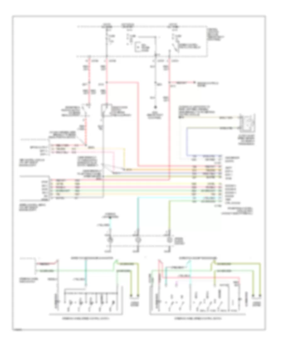
Cruise Control Wiring Diagram for Ford Expedition 2003
 https://portal-diagnostov.com/license.html
Automotive Electricians Portal FZCO
Automotive Electricians Portal FZCO
https://portal-diagnostov.com/license.html
https://portal-diagnostov.com/license.html
Automotive Electricians Portal FZCO
Automotive Electricians Portal FZCOList of elements for Cruise Control Wiring Diagram for Ford Expedition 2003:
- (in back-up lamp switch to rear lamp feed harness, near breakout to powertrain control module) s138
- (in main harness, near breakout to brake pedal position switch)
- (near breakout to left front wheel speed sensor) s103
- (near breakout to thermostatic expansion valve switch assembly)
- Abs control module (on left side of engine compt)
- Air bag sliding contact
- Bpp sw output
- Brake pedal position switch (on brake pedal support)
- C175b
- C175t
- C270a
- C270b
- C270e
- C270f
- Central junction box (cjb) (behind right kick panel)
- Ctrl sw gnd
- Deactivator switch (on brake pedal support)
- Engine controls system
- Expedition (except eddie bauer)
- Expedition eddie bauer & navigator
- Fuse 10a
- Fuse 5a
- Fuse 7.5a
- G200 (behind right kick panel)
- Horns system
- Hot at all times
- Hot in run or start
- Illumination
- Interior lights system
- Nca
- Off
- Oss sensor
- Output shaft speed sensor (on rear of transmission)
- Pcm power diode
- Powertrain control module (pcm) (on right side of firewall)
- Resume
- S110
- S111
- S112
- S133
- S2003
- S203
- S277
- Scp (+)
- Scp (-)
- Scs sig
- Scs sig a
- Scs sig b
- Scs sig c
- Set (+)
- Set (-)
- Sig
- Sig a
- Sig b
- Sig c
- Sig rtn
- Speed control fan clutch relay
- Speed control servo (on left side of engine compt)
- Steering wheel radio switch
- Steering wheel/speed control switch
- Tan
- Vbatt
- Vpwr
- Vref
DEFOGGERS
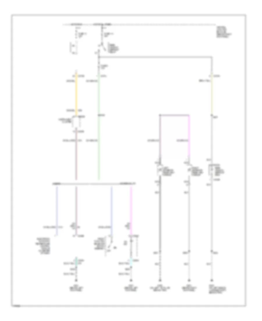
Defoggers Wiring Diagram for Ford Expedition 2003
 https://portal-diagnostov.com/license.html
Automotive Electricians Portal FZCO
Automotive Electricians Portal FZCO
https://portal-diagnostov.com/license.html
https://portal-diagnostov.com/license.html
Automotive Electricians Portal FZCO
Automotive Electricians Portal FZCOList of elements for Defoggers Wiring Diagram for Ford Expedition 2003:
- C208a
- C220b
- C228b
- C270e
- C270j
- C270n
- C294c
- C402a
- C402b
- Central junction box (cjb) (behind right kick panel)
- Electronic automatic temperature control module (in center of dash)
- Front function selector switch assembly
- Fuse 114 40a
- Fuse 13 10a
- Fuse 8 10a
- G201 (behind right kick panel)
- G300 (on left ``b" pillar, behind trim)
- G301 (behind left kick panel
- G301 (behind left kick panel)
- G402 (on left side of luggage compt, behind trim)
- Hot at all times
- Hot in run
- Instrument cluster
- Left exterior rear view mirror
- Nca
- Off
- On ind
- Rear window defrost grid
- Rear window defrost relay
- Right exterior rear view mirror
- S208
- S348
- S402
- S427
- S501
- S600
- W/ eatc
- W/ mannual a/c
ELECTRONIC POWER STEERING
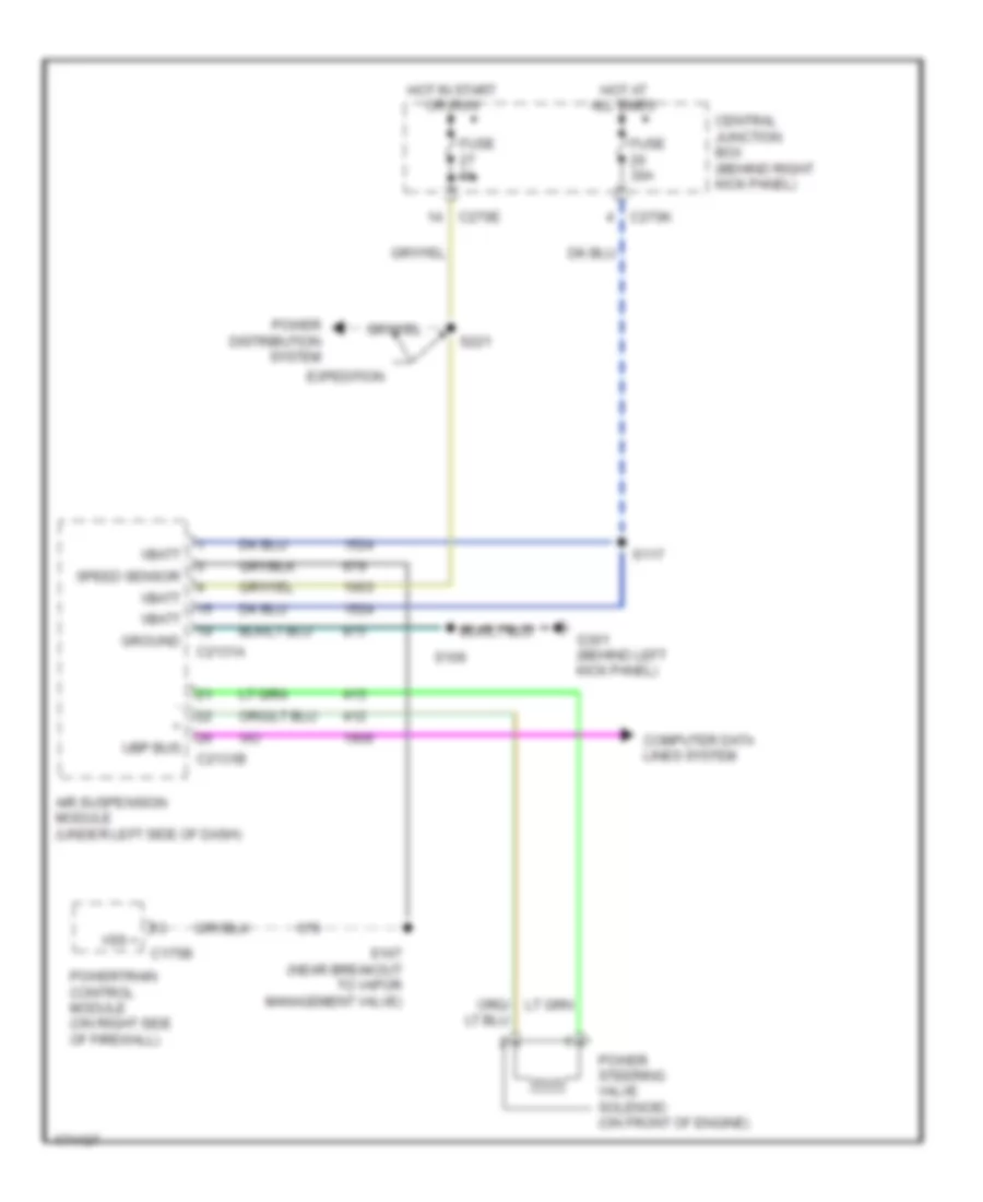
Electronic Power Steering Wiring Diagram for Ford Expedition 2003
 https://portal-diagnostov.com/license.html
Automotive Electricians Portal FZCO
Automotive Electricians Portal FZCO
https://portal-diagnostov.com/license.html
https://portal-diagnostov.com/license.html
Automotive Electricians Portal FZCO
Automotive Electricians Portal FZCOList of elements for Electronic Power Steering Wiring Diagram for Ford Expedition 2003:
- Air suspension module (under left side of dash)
- C175b
- C2131a
- C2131b
- C270e
- C270k
- Central junction box (behind right kick panel)
- Computer data lines system
- Expedition
- Fuse 30a
- Fuse 5a
- G301 (behind left kick panel)
- Ground
- Hot at all times
- Hot in start or run
- Power distribution system
- Power steering valve solenoid (on front of engine)
- Powertrain control module (on right side of firewall)
- S106
- S107 (near breakout to vapor management valve)
- S117
- S221
- Speed sensor
- Ubp bus
- Vbatt
- Vss +
ELECTRONIC SUSPENSION
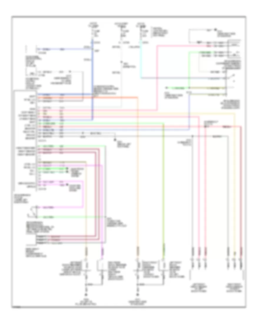
Electronic Suspension Wiring Diagram for Ford Expedition 2003
 https://portal-diagnostov.com/license.html
Automotive Electricians Portal FZCO
Automotive Electricians Portal FZCO
https://portal-diagnostov.com/license.html
https://portal-diagnostov.com/license.html
Automotive Electricians Portal FZCO
Automotive Electricians Portal FZCOList of elements for Electronic Suspension Wiring Diagram for Ford Expedition 2003:
- (expedition)
- (in breakout to c110) s119
- (in engine control sensor harness, near breakout to deactivator switch) s117
- Air suspension compressor assembly (at right front of engine compt)
- Air suspension module (under left side of dash)
- Air suspension service switch (behind access panel, on left rear quarter trim panel, near liftgate)
- Air suspension solid state relay (at right front of engine compt)
- C175b
- C2131a
- C2131b
- C270c
- C270e
- C270k
- C3184b
- Central junction box (behind right kick panel)
- Comp asmbly
- Computer data lines system
- Electronic power steering system
- Four-wheel drive control module (at left "b" pillar)
- Fuse 30a
- Fuse 50a
- Fuse 5a
- G101 (near right side of radiator)
- G300 (on left "b" pillar, behind trim)
- G301 (behind left kick panel)
- Ground
- Height sens feed
- Height sens ret
- Height sens sig
- Hot at all times
- Hot in start or run
- Left front height sensor (at left shock tower)
- Left front shock absorber solenoid valve (on left shock tower)
- Left rear shock absorber solenoid valve (under left rear side of vehicle, near shock mount)
- Lf height sens
- Lf sol vlv
- Lr sol vlv
- Nca
- Pnk
- Powertrain control module (on right side of firewall)
- Rear height sensor (under rear of vehicle, near axle)
- Relay ctrl
- Rf height sens
- Rf sol vlv
- Right front height sensor (at right shock tower)
- Right front shock absorber solenoid valve (on right shock tower)
- Right rear shock absorber solenoid valve (under right rear side of vehicle, near shock mount)
- Rr sol vlv
- S106
- S107 (near breakout to vapor management valve)
- S116
- S118
- S120
- S121 (in breakout to c110)
- S221
- S357
- S374 (in body main harness, near breakout to c327)
- S454
- Sens pwr
- Sens ret
- Service switch
- Sol +
- Sol -
- Tan
- Ubp bus
- Vbatt
- Vpwr
- Vss +
ENGINE PERFORMANCE
4.6L
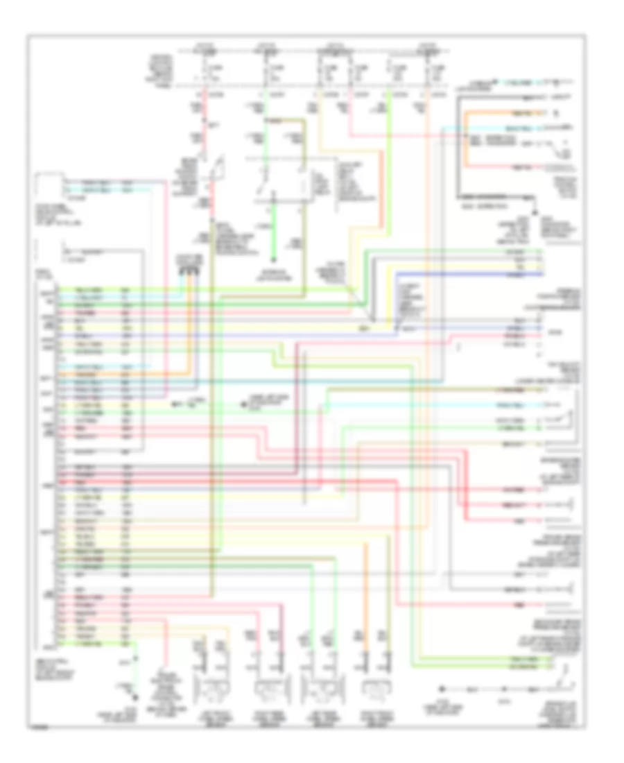
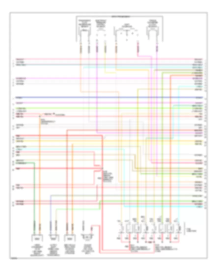
4.6L, Engine Performance Wiring Diagram (1 of 4) for Ford Expedition 2003
 https://portal-diagnostov.com/license.html
Automotive Electricians Portal FZCO
Automotive Electricians Portal FZCO
https://portal-diagnostov.com/license.html
https://portal-diagnostov.com/license.html
Automotive Electricians Portal FZCO
Automotive Electricians Portal FZCOList of elements for 4.6L, Engine Performance Wiring Diagram (1 of 4) for Ford Expedition 2003:
- (engine sensor harn, near breakout to c1373) s110
- (engine sensor harn, near breakout to c1373) s111
- (left b-pillar) g300
- (right rear of engine compt)
- A/c clu rly ctrl
- A/c system
- Ac term signal
- Acc
- Anti-theft system
- Battery
- Bps switch output
- C fan spd ctrl
- C175b
- C270a
- C270b
- C270d
- C270f
- C270g
- C270k
- Canister vent
- Central junction box (right kick panel)
- Charging system
- Cool fan ctrl sig
- Cooling fan system
- Cruise control system
- Data link connector (under driver side dash panel)
- Evap valve
- F pump rly ctrl
- Fuel pump assembly (fuel tank)
- Fuel pump relay
- Fuel tank pressure transducer sensor (in fuel tank)
- Fuse
- Fuse 15a
- Fuse 20a
- Fuse 7.5a
- G102
- Gen comm cir
- Gen monitor
- Ground
- Hot at all times
- Hot in run or start
- Iat input
- Ignition switch
- Inertia fuel shut-off switch (rear end of vehicle)
- Instument cluster system
- Lock
- Maf output
- Maf sig rtn
- Module prog sig
- Navigation, wiper/washer, and sound systems (vehicle speed signal)
- Nca
- Od cancel sw
- Off
- Overdrive cancel switch
- Pcm power diode
- Pcm power relay
- Powertrain control module (right side of engine bulkhead)
- Pres sensor
- Psp signal
- Red
- Red/pnk
- Ref voltage
- Run
- Rx sig
- S108
- S133
- S203
- S454
- Scp -
- Scp bus +
- Servo common
- Servo sig a
- Servo sig b
- Servo sig c
- Signal return
- Spd ctrl sw in
- St and run sig
- St rly ctrl
- St whl ctrl gnd
- Start
- Starting system
- Sw poer out
- Tan
- Theft ind ctrl
- Tps signal
- Transmission system
- Tx sig
- Vss+
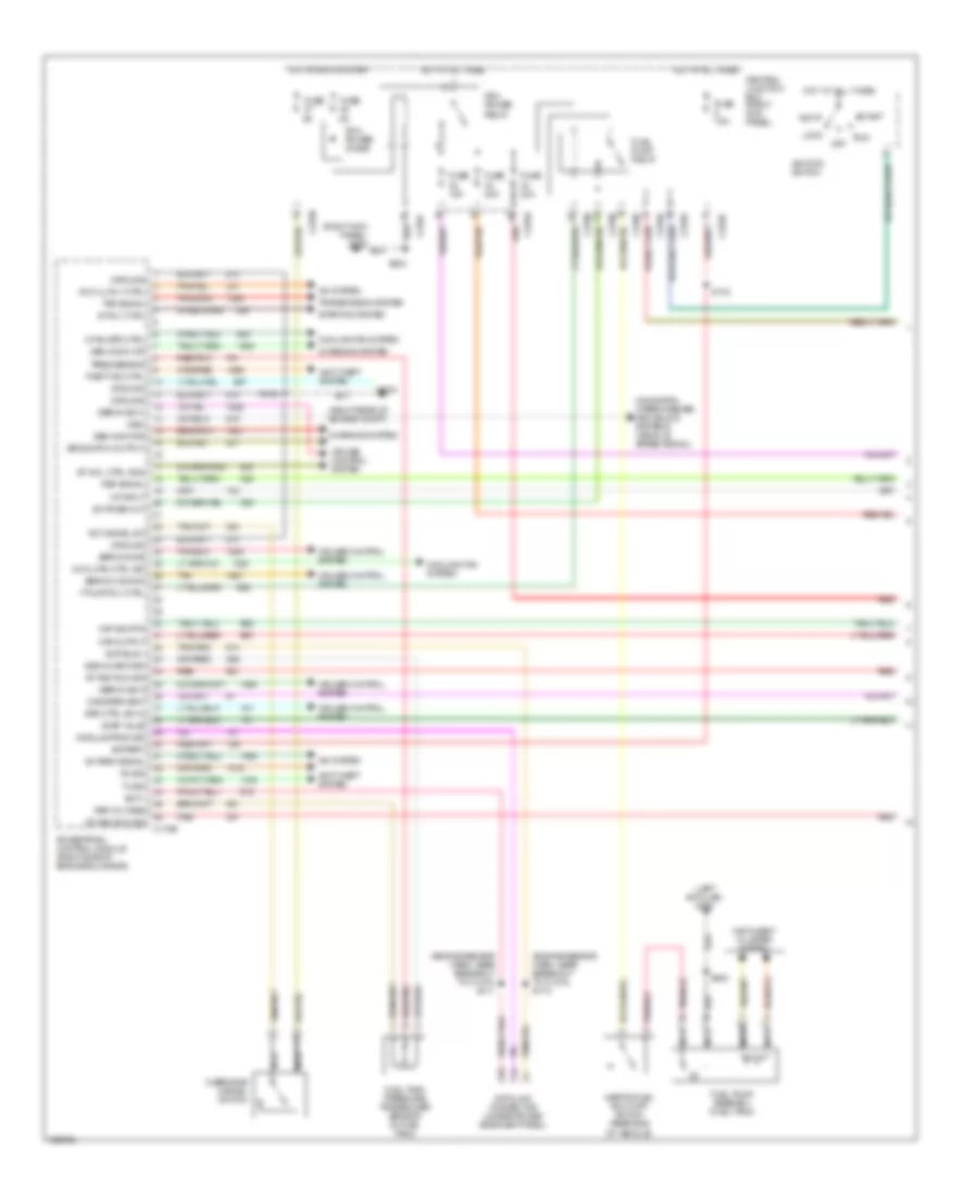
4.6L, Engine Performance Wiring Diagram (2 of 4) for Ford Expedition 2003
 https://portal-diagnostov.com/license.html
Automotive Electricians Portal FZCO
Automotive Electricians Portal FZCO
https://portal-diagnostov.com/license.html
https://portal-diagnostov.com/license.html
Automotive Electricians Portal FZCO
Automotive Electricians Portal FZCOList of elements for 4.6L, Engine Performance Wiring Diagram (2 of 4) for Ford Expedition 2003:
- (above rear axle) evap canister vent control solenoid
- (engine crtl harn, near breakout to c129) s125
- Coils on plug
- Crankshaft position sensor (front of engine)
- Differential pressure feedback egr (dpfe) sensor (left top of engine)
- G102 (right rear of engine compt)
- Ignition trans- former capacitor
- Inlet manifold runner control module (4.6l) (front of engine)
- Intake air temperature (iat) sensor (in intake system)
- Mass airflow (maf) sensor (in intake system)
- Nca
- Power steering pressure switch (left side of engine compt)
- Red
- S108
- S124
- S127 (engine ctrl harn, near breakout to c187)
- S129
- S132
- Throttle position (tp) sensor (on throttle body)
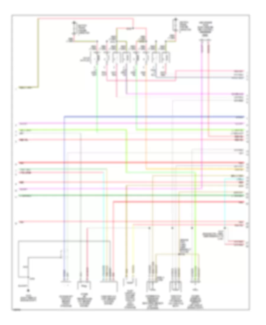
4.6L, Engine Performance Wiring Diagram (3 of 4) for Ford Expedition 2003
 https://portal-diagnostov.com/license.html
Automotive Electricians Portal FZCO
Automotive Electricians Portal FZCO
https://portal-diagnostov.com/license.html
https://portal-diagnostov.com/license.html
Automotive Electricians Portal FZCO
Automotive Electricians Portal FZCOList of elements for 4.6L, Engine Performance Wiring Diagram (3 of 4) for Ford Expedition 2003:
- (left rear side of engine compt)
- 4r70w transmission
- A/c system
- Egr vacuum regulator solenoid (left side of engine)
- Electronic pressure control solenoid
- Fuel injectors
- Idle air control (iac) valve (on throttle body)
- Output shaft speed (oss) sensor (rear of transmission)
- Red
- S105 (near breakout to c124)
- S109 (eng ctrl sensor harn, near red breakout to c1373)
- S126 (eng ctrl sensor harn, near breakout to c1066)
- S131 (eng ctrl sensor harn, near breakout to c194)
- Shift solenoids
- Tan
- Tan/ red
- Tan/red
- Torque converter clutch solenoid
- Transmission fluid temperature sensor
- Vapor management valve
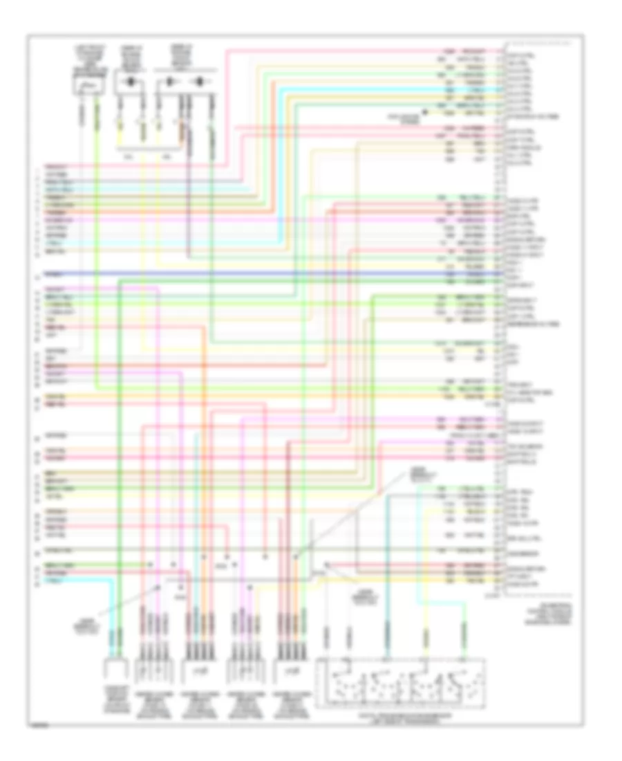
4.6L, Engine Performance Wiring Diagram (4 of 4) for Ford Expedition 2003
 https://portal-diagnostov.com/license.html
Automotive Electricians Portal FZCO
Automotive Electricians Portal FZCO
https://portal-diagnostov.com/license.html
https://portal-diagnostov.com/license.html
Automotive Electricians Portal FZCO
Automotive Electricians Portal FZCOList of elements for 4.6L, Engine Performance Wiring Diagram (4 of 4) for Ford Expedition 2003:
- (left front of engine) cylinder head temperature (cht) sensor
- (near breakout to c171)
- (near breakout to c175t)
- (pins 4-10 not used)
- (rear of engine) knock sensor (4.6l)
- (rear of engine) knock sensor (5.4l)
- 4.6l
- 5.4l
- C175e
- C175t
- Camshaft position sensor (on front of engine)
- Ckp +
- Ckp -
- Cmp input
- Cooling fan system
- Cop 1 ctrl
- Cop 2 ctrl
- Cop 3 ctrl
- Cop 4 ctrl
- Cop 5 ctrl
- Cop 6 ctrl
- Cop 7 ctrl
- Cop 8 ctrl
- Cyl head tmp sns
- Digital transmission range sensor (left side of transmission)
- Dpfe input
- Dtr, tr1
- Dtr, tr2
- Dtr, tr3a
- Dtr, tr4
- Epc sol ctrl
- Evr ctrl
- Heated oxygen sensor (ho2s) 11 (on engine exhaust pipe)
- Heated oxygen sensor (ho2s) 12 (on engine exhaust pipe)
- Heated oxygen sensor (ho2s) 21 (on engine exhaust pipe)
- Heated oxygen sensor (ho2s) 22 (on engine exhaust pipe)
- Ho2s 11 htr
- Ho2s 11 input
- Ho2s 12 htr
- Ho2s 12 input
- Ho2s 21 htr
- Ho2s 21 input
- Ho2s 22 htr
- Ho2s 22 input
- Iac ctrl
- Imrc module
- Inj 1 ctrl
- Inj 2 ctrl
- Inj 3 ctrl
- Inj 4 ctrl
- Inj 5 ctrl
- Inj 6 ctrl
- Inj 7 ctrl
- Inj 8 ctrl
- Ks 1 +
- Ks 1 -
- Ks 2 +
- Ks 2 -
- Nca
- Oss sensor
- Powertrain control module (right side of engine bulkhead)
- R n
- Reference voltage
- S128
- S138
- S140
- Shift sol a
- Shift sol b
- Signal return
- St and run voltage
- Tan
- Tan/red
- Tcc solenoid
- Tft input
- Tps input
5.4L
5.4L, Engine Performance Wiring Diagram (1 of 4) for Ford Expedition 2003
 https://portal-diagnostov.com/license.html
Automotive Electricians Portal FZCO
Automotive Electricians Portal FZCO
https://portal-diagnostov.com/license.html
https://portal-diagnostov.com/license.html
Automotive Electricians Portal FZCO
Automotive Electricians Portal FZCOList of elements for 5.4L, Engine Performance Wiring Diagram (1 of 4) for Ford Expedition 2003:
- (engine sensor harn, near breakout to c1373) s110
- (engine sensor harn, near breakout to c1373) s111
- (left b-pillar) g300
- (right rear of engine compt)
- A/c clu rly ctrl
- A/c system
- Ac term signal
- Acc
- Anti-theft system
- Battery
- Bps switch output
- C fan spd ctrl
- C175b
- C270a
- C270b
- C270d
- C270f
- C270g
- C270k
- Canister vent
- Central junction box (right kick panel)
- Charging system
- Cool fan ctrl sig
- Cooling fan system
- Cruise control system
- Data link connector (under driver side dash panel)
- Evap valve
- F pump rly ctrl
- Fuel pump assembly (fuel tank)
- Fuel pump relay
- Fuel tank pressure transducer sensor (in fuel tank)
- Fuse
- Fuse 15a
- Fuse 20a
- Fuse 7.5a
- G102
- Gen comm cir
- Gen monitor
- Ground
- Hot at all times
- Hot in run or start
- Iat input
- Ignition switch
- Inertia fuel shut-off switch (rear end of vehicle)
- Instument cluster system
- Lock
- Maf output
- Maf sig rtn
- Module prog sig
- Navigation, wiper/washer, and sound systems (vehicle speed signal)
- Nca
- Od cancel sw
- Off
- Overdrive cancel switch
- Pcm power diode
- Pcm power relay
- Powertrain control module (right side of engine bulkhead)
- Pres sensor
- Psp signal
- Red
- Red/pnk
- Ref voltage
- Run
- Rx sig
- S108
- S133
- S203
- S454
- Scp -
- Scp bus +
- Servo common
- Servo sig a
- Servo sig b
- Servo sig c
- Signal return
- Spd ctrl sw in
- St and run sig
- St rly ctrl
- St whl ctrl gnd
- Start
- Starting system
- Sw poer out
- Tan
- Theft ind ctrl
- Tps signal
- Transmission system
- Tx sig
- Vss+
5.4L, Engine Performance Wiring Diagram (2 of 4) for Ford Expedition 2003
 https://portal-diagnostov.com/license.html
Automotive Electricians Portal FZCO
Automotive Electricians Portal FZCO
https://portal-diagnostov.com/license.html
https://portal-diagnostov.com/license.html
Automotive Electricians Portal FZCO
Automotive Electricians Portal FZCOList of elements for 5.4L, Engine Performance Wiring Diagram (2 of 4) for Ford Expedition 2003:
- (above rear axle) evap canister vent control solenoid
- (engine crtl harn, near breakout to c129) s125
- Coils on plug
- Crankshaft position sensor (front of engine)
- Differential pressure feedback egr (dpfe) sensor (left top of engine)
- G102 (right rear of engine compt)
- Ignition trans- former capacitor
- Inlet manifold runner control module (4.6l) (front of engine)
- Intake air temperature (iat) sensor (in intake system)
- Mass airflow (maf) sensor (in intake system)
- Nca
- Power steering pressure switch (left side of engine compt)
- Red
- S108
- S124
- S127 (engine ctrl harn, near breakout to c187)
- S129
- S132
- Throttle position (tp) sensor (on throttle body)
5.4L, Engine Performance Wiring Diagram (3 of 4) for Ford Expedition 2003
 https://portal-diagnostov.com/license.html
Automotive Electricians Portal FZCO
Automotive Electricians Portal FZCO
https://portal-diagnostov.com/license.html
https://portal-diagnostov.com/license.html
Automotive Electricians Portal FZCO
Automotive Electricians Portal FZCOList of elements for 5.4L, Engine Performance Wiring Diagram (3 of 4) for Ford Expedition 2003:
- (left rear side of engine compt)
- 4r70w transmission
- A/c system
- Egr vacuum regulator solenoid (left side of engine)
- Electronic pressure control solenoid
- Fuel injectors
- Idle air control (iac) valve (on throttle body)
- Output shaft speed (oss) sensor (rear of transmission)
- Red
- S105 (near breakout to c124)
- S109 (eng ctrl sensor harn, near red breakout to c1373)
- S126 (eng ctrl sensor harn, near breakout to c1066)
- S131 (eng ctrl sensor harn, near breakout to c194)
- Shift solenoids
- Tan
- Tan/ red
- Tan/red
- Torque converter clutch solenoid
- Transmission fluid temperature sensor
- Vapor management valve
5.4L, Engine Performance Wiring Diagram (4 of 4) for Ford Expedition 2003
 https://portal-diagnostov.com/license.html
Automotive Electricians Portal FZCO
Automotive Electricians Portal FZCO
https://portal-diagnostov.com/license.html
https://portal-diagnostov.com/license.html
Automotive Electricians Portal FZCO
Automotive Electricians Portal FZCOList of elements for 5.4L, Engine Performance Wiring Diagram (4 of 4) for Ford Expedition 2003:
- (left front of engine) cylinder head temperature (cht) sensor
- (near breakout to c171)
- (near breakout to c175t)
- (pins 4-10 not used)
- (rear of engine) knock sensor (4.6l)
- (rear of engine) knock sensor (5.4l)
- 4.6l
- 5.4l
- C175e
- C175t
- Camshaft position sensor (on front of engine)
- Ckp +
- Ckp -
- Cmp input
- Cooling fan system
- Cop 1 ctrl
- Cop 2 ctrl
- Cop 3 ctrl
- Cop 4 ctrl
- Cop 5 ctrl
- Cop 6 ctrl
- Cop 7 ctrl
- Cop 8 ctrl
- Cyl head tmp sns
- Digital transmission range sensor (left side of transmission)
- Dpfe input
- Dtr, tr1
- Dtr, tr2
- Dtr, tr3a
- Dtr, tr4
- Epc sol ctrl
- Evr ctrl
- Heated oxygen sensor (ho2s) 11 (on engine exhaust pipe)
- Heated oxygen sensor (ho2s) 12 (on engine exhaust pipe)
- Heated oxygen sensor (ho2s) 21 (on engine exhaust pipe)
- Heated oxygen sensor (ho2s) 22 (on engine exhaust pipe)
- Ho2s 11 htr
- Ho2s 11 input
- Ho2s 12 htr
- Ho2s 12 input
- Ho2s 21 htr
- Ho2s 21 input
- Ho2s 22 htr
- Ho2s 22 input
- Iac ctrl
- Imrc module
- Inj 1 ctrl
- Inj 2 ctrl
- Inj 3 ctrl
- Inj 4 ctrl
- Inj 5 ctrl
- Inj 6 ctrl
- Inj 7 ctrl
- Inj 8 ctrl
- Ks 1 +
- Ks 1 -
- Ks 2 +
- Ks 2 -
- Nca
- Oss sensor
- Powertrain control module (right side of engine bulkhead)
- R n
- Reference voltage
- S128
- S138
- S140
- Shift sol a
- Shift sol b
- Signal return
- St and run voltage
- Tan
- Tan/red
- Tcc solenoid
- Tft input
- Tps input
EXTERIOR LIGHTS
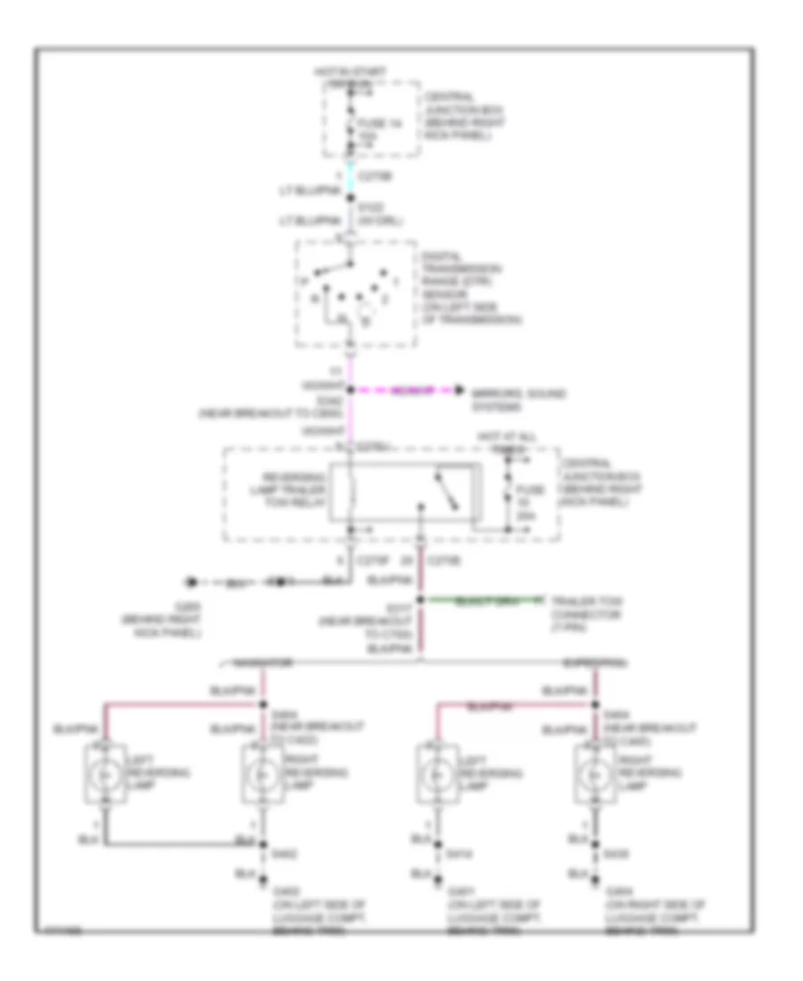
Back-up Lamps Wiring Diagram for Ford Expedition 2003
 https://portal-diagnostov.com/license.html
Automotive Electricians Portal FZCO
Automotive Electricians Portal FZCO
https://portal-diagnostov.com/license.html
https://portal-diagnostov.com/license.html
Automotive Electricians Portal FZCO
Automotive Electricians Portal FZCOList of elements for Back-up Lamps Wiring Diagram for Ford Expedition 2003:
- C270b
- C270e
- C270f
- C270j
- Central junction box (behind right kick panel)
- Digital transmission range (dtr) sensor (on left side of transmission)
- Expedition
- Fuse 14 10a
- Fuse 20a
- G200 (behind right kick panel)
- G401 (on left side of luggage compt, behind trim)
- G402 (on left side of luggage compt, behind trim)
- G404 (on right side of luggage compt, behind trim)
- Hot at all times
- Hot in start or run
- Left reversing lamp
- Mirrors, sound systems
- Navigator
- Reversing lamp trailer tow relay
- Right reversing lamp
- S122 (w/ drl)
- S203
- S317 (near breakout to c700)
- S342 (near breakout to c800)
- S402
- S414
- S436
- S464 (near breakout to c405)
- S464 (near breakout to c422)
- Trailer tow connector (7-pin)
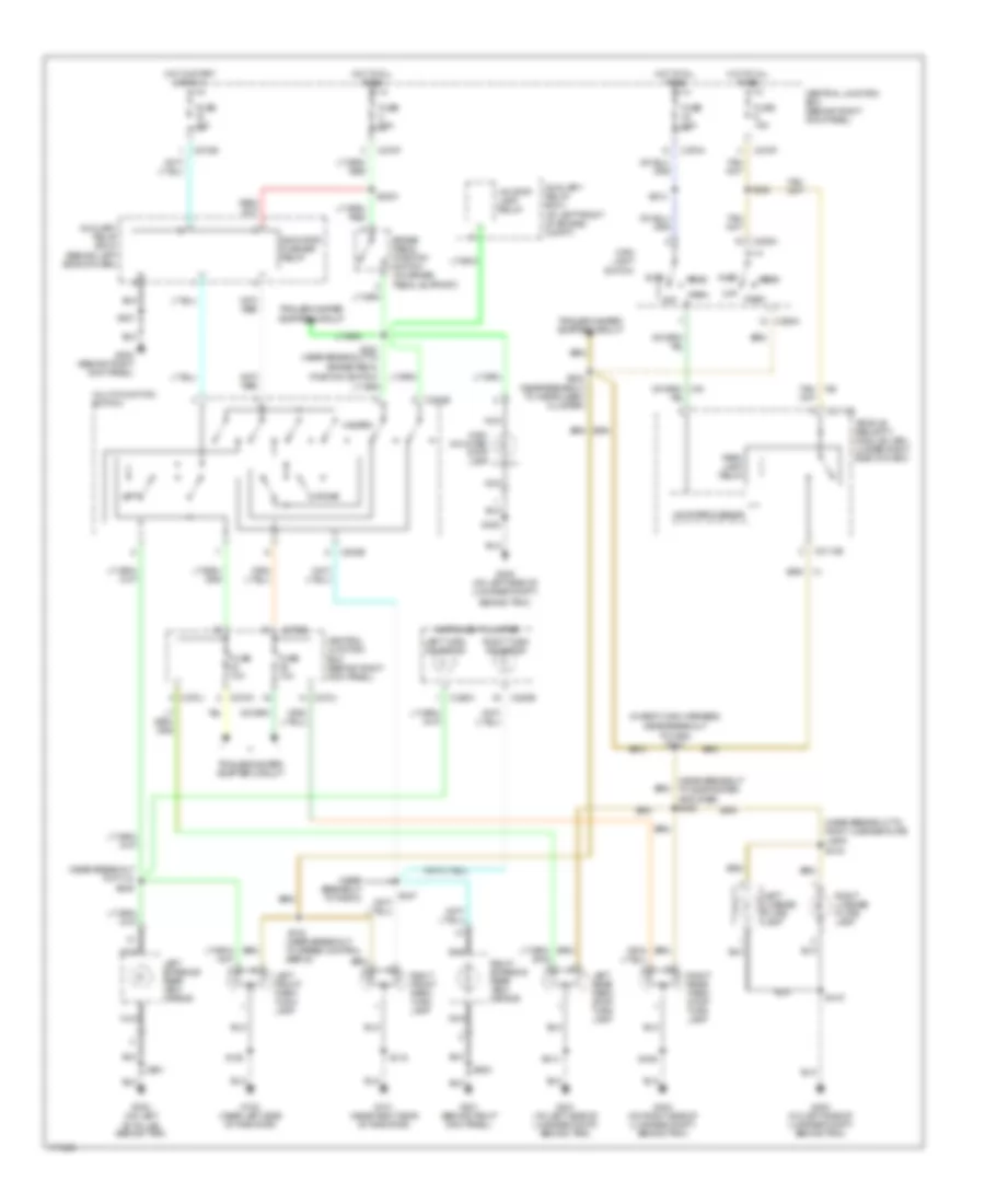
Exterior Lamps Wiring Diagram for Ford Expedition 2003
 https://portal-diagnostov.com/license.html
Automotive Electricians Portal FZCO
Automotive Electricians Portal FZCO
https://portal-diagnostov.com/license.html
https://portal-diagnostov.com/license.html
Automotive Electricians Portal FZCO
Automotive Electricians Portal FZCOList of elements for Exterior Lamps Wiring Diagram for Ford Expedition 2003:
- "b" pillar, behind trim)
- (at left front of engine compt)
- (behind left side of dash)
- (in body main harness,
- (near breakout to p113) s246
- (near breakout to radio)
- (near breakout to right license plate lamp) s416
- (near breakout to subwoofer amplifier) s403
- Auto
- Auxiliary relay box 1
- Auxiliary relay box 3
- Behind trim)
- Brake pedal position switch (on brake pedal support)
- C202b
- C205a
- C2113b
- C220a
- C220b
- C270e
- C270f
- C270h
- C270j
- C270k
- Central junction box (behind right kick panel)
- Fuse 10a
- Fuse 15a
- Fuse 20a
- G100 (near left side of radiator)
- G101 (near right side of radiator)
- G200 (behind right kick panel)
- G201 (behind right kick panel)
- G300 (on left
- G401 (on left side of luggage compt, behind trim)
- G402 (on left side of luggage compt,
- G402 (on left side of luggage compt, behind trim)
- G404 (on right side of luggage compt, behind trim)
- Hazard
- Head
- High mounted stop lamp
- Hot at all times
- Hot in start or run
- Indicator flasher relay
- Instrument cluster
- Ivd stop lamp relay
- Left
- Left exterior rear view mirror
- Left front park/ turn lamp
- Left license plate lamp
- Left rear park/ stop/ turn lamp
- Left turn indicator
- Main light switch
- Microprocessor
- Multi-function switch
- Nca
- Near breakout to c465) s312
- Off
- Park
- Park lamp relay
- Position switch)
- Right
- Right exterior rear view mirror
- Right front park/ turn lamp
- Right license plate lamp
- Right rear park/ stop/ turn lamp
- Right turn indicator
- S100
- S102 (near breakout to speed control servo)
- S116
- S2001
- S201
- S203
- S212
- S224 (near breakout to instrument cluster)
- S231 (near breakout to brake pedal
- S247
- S402
- S414
- S415
- S436
- S501
- S600
- Tan/
- Trailer/camper adapter circuit
- Vehicle security module (vsm) (under right side of dash)
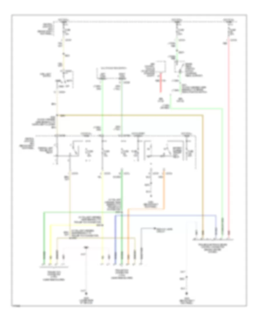
Trailer/Camper Adapter Wiring Diagram for Ford Expedition 2003
 https://portal-diagnostov.com/license.html
Automotive Electricians Portal FZCO
Automotive Electricians Portal FZCO
https://portal-diagnostov.com/license.html
https://portal-diagnostov.com/license.html
Automotive Electricians Portal FZCO
Automotive Electricians Portal FZCOList of elements for Trailer/Camper Adapter Wiring Diagram for Ford Expedition 2003:
- (behind center of dash)
- (in taillamp harness, near breakout to trailer tow connector)
- (in taillamp harness, near breakout to trailer tow connector) s451
- (in taillamp harness, near breakout to trailer tow connector) s452
- (near rear bumper)
- Abs control module (at left side of engine compt)
- Abs w/ ivd
- Abs w/o ivd
- Auto
- Back-up lamps circuit
- Battery charge trailer tow relay
- Brake pedal position switch (on brake pedal support)
- C202b
- C205a
- C270a
- C270e
- C270f
- C270g
- C270j
- C270k
- C270n
- Central junction box (behind right kick panel)
- Fuse 10a
- Fuse 15a
- Fuse 20a
- Fuse 30a
- G200 (behind right kick panel)
- G400 (under rear of vehicle)
- Head
- Hot at all times
- Hot in start or run
- Left turn signal
- Main light switch
- Multi-function switch
- Off
- Park
- Parking lamp trailer tow relay
- Red
- Right turn signal
- S2001
- S202
- S203
- S224 (in main harness, near breakout to instrument cluster)
- S231 (in main harness, near breakout to brake pedal position switch)
- S450
- S453
- Trailer electronic brake control connector
- Trailer tow connector (4-pin)
- Trailer tow connector (7-pin)
GROUND DISTRIBUTION
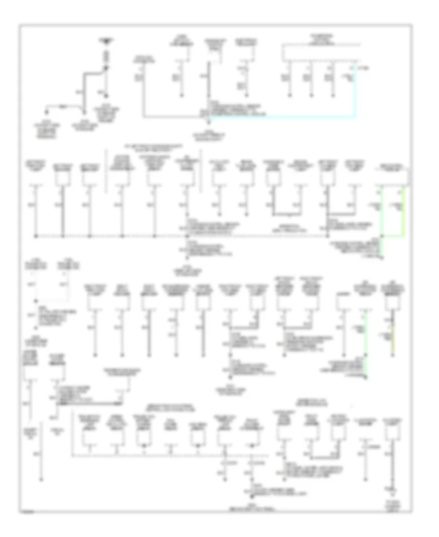
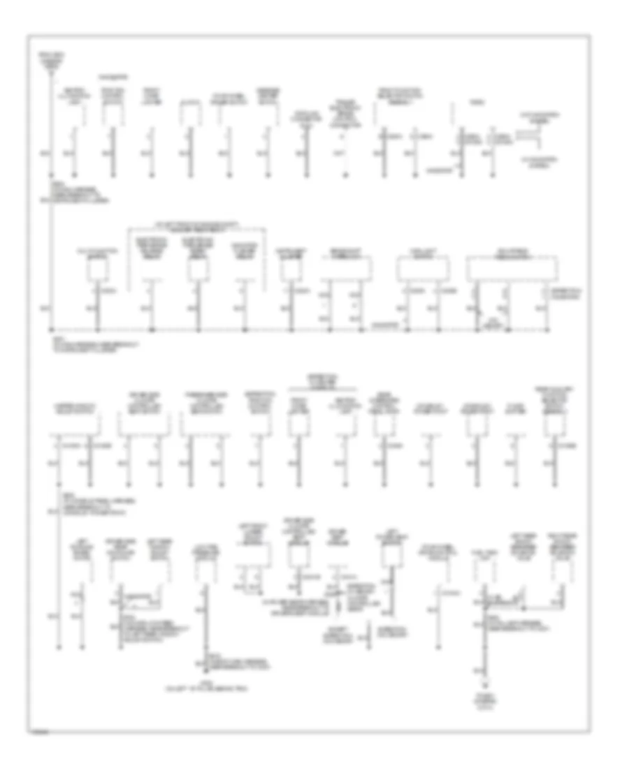
Ground Distribution Wiring Diagram (1 of 4) for Ford Expedition 2003
 https://portal-diagnostov.com/license.html
Automotive Electricians Portal FZCO
Automotive Electricians Portal FZCO
https://portal-diagnostov.com/license.html
https://portal-diagnostov.com/license.html
Automotive Electricians Portal FZCO
Automotive Electricians Portal FZCOList of elements for Ground Distribution Wiring Diagram (1 of 4) for Ford Expedition 2003:
- (at left front of engine compt) auxiliary relay box 1
- (behind right kick panel) central junction box (cjb)
- (expedition, w/o center console)
- 4-pin trailer tow connector
- 7-pin trailer tow connector
- A/c clutch field coil
- A/c compressor clutch diode
- Abs control module
- Air suspension compressor assembly
- Air suspension solid state relay
- Ashtray illumination lamp
- Battery
- Blower motor resistor
- Brake fluid level switch
- C175b
- C2065b
- C270e
- C270f
- Crankshaft position shield
- Data link connector
- Daytime running lamps (drl) headlamp relay
- Daytime running lamps (drl) ignition relay
- Electronic fan clutch
- Engine compartment lamp
- Except manual a/c
- Expedition, early production
- Front blower motor relay
- Front cigar lighter
- G100 (near left side of radiator)
- G101 (near right side of radiator)
- G102 (on right rear of engine compt)
- G103 (on right side of engine compt, on fender)
- G104 (on right side of engine compt, on frame rail)
- G105 (on right side of engine)
- G200 (behind right kick panel)
- G400 (under rear of vehicle)
- Glove box lamp
- Heater blower control module
- High beam relay
- Horn
- Illumination dimmer
- Instrument panel power point
- Left front fog lamp
- Left front high beam lamp
- Left front low beam lamp
- Left front park/turn lamp
- Left front shock absorber solenoid valve
- Left front side lamp
- Manual a/c
- Mass air flow (maf) sensor
- Nca
- Near breakout to g101)
- Pcm power relay
- Powertrain control module (pcm)
- Right front fog lamp
- Right front high beam lamp
- Right front low beam lamp
- Right front park/turn lamp
- Right front shock absorber solenoid valve
- Right front side lamp
- S100 (in engine control sensor harness, near breakout to c133)
- S101 (in engine control sensor harness, in breakout to abs control module)
- S104 (in engine control sensor harness, near breakout to deactivator switch)
- S118 (in engine control sensor harness, near breakout to g101)
- S135 (in headlamps harness, in breakout to c133)
- S450 (in taillamp harness, near breakout to trailer tow connector)
- Speed control fan clutch relay
- Temperature blend door actuator
- To front cigar lighter)
- To s202 (diagram 2 of 4)
- Trailer tow battery charge relay
- Trailer tow parking lamp relay
- Trailer tow reversing lamp relay
- Washer fluid level switch
- Windshield wiper motor
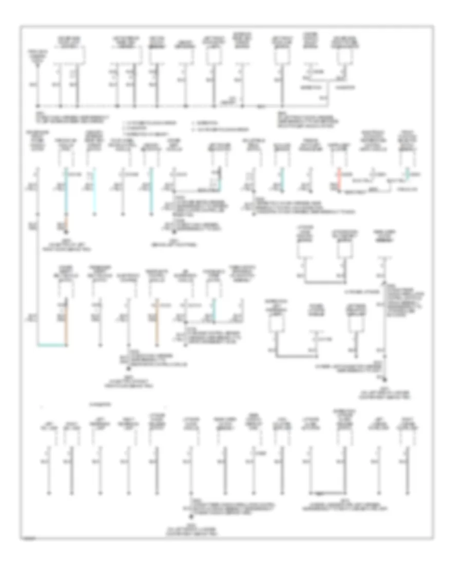
Ground Distribution Wiring Diagram (2 of 4) for Ford Expedition 2003
 https://portal-diagnostov.com/license.html
Automotive Electricians Portal FZCO
Automotive Electricians Portal FZCO
https://portal-diagnostov.com/license.html
https://portal-diagnostov.com/license.html
Automotive Electricians Portal FZCO
Automotive Electricians Portal FZCOList of elements for Ground Distribution Wiring Diagram (2 of 4) for Ford Expedition 2003:
- (at left front of engine compt) auxiliary relay box 3
- (expedition) (navigator)
- (expedition) traction control switch
- (expedition, w/ center console)
- (in power seats harness, near breakout to driver's seat module)
- (navigator)
- (w/ navigation
- (w/o navigation
- Adjustable pedal switch
- Ashtray illumination lamp
- Brake shift interlock
- C202a
- C205b
- C205c
- C2188a
- C220a
- C290a
- C290a c2188c
- C294a b
- C294c
- C3031b
- C3184a
- C3193a
- C3193b
- C3198b
- C341a
- C349a
- Clock
- Console 1 power point
- Console 2 power point
- Data link connector (dlc)
- Driver seat module
- Driver side climate controlled seat module
- Driver side climate controlled seat switch
- Driver side rear door ajar switch
- Electronic park brake release relay
- Electronic park brake reset relay
- Except expedition w/o memory
- Expedition w/ memory, climate controlled seats
- Expedition w/o memory
- Floor shifter
- Four-wheel drive control module
- Four-wheel driver switch
- From s203 (diagram 1 of 4)
- Front cigar lighter
- Front function selector switch assembly
- Fuel tank unit
- G300 (on left ``b" pillar, behind trim)
- Indicator flasher relay
- Instrument cluster
- Left front lumbar adjust switch
- Left power seat switch
- Left rear shock absorber solenoid valve
- Left rear window adjust switch
- Left running board motor
- Low tire pressure module
- Main light switch
- Master window adjust switch
- Message center switch
- Multi-function switch
- Navigator
- Nca
- Passenger side climate controlled seat switch
- Radio
- Rear auxiliary function selector switch assembly
- Rear integrated control panel (ricp)
- Right rear shock absorber solenoid valve
- S201 (in main harness, near breakout to instrument cluster)
- S205 (in console panel harness, near breakout to console 1 power point)
- S385
- System)
- To s501 (diagram 3 of 4)
- Traction control switch
- Trailer electronic brake control connector
- W/ air suspension
- W/o memory
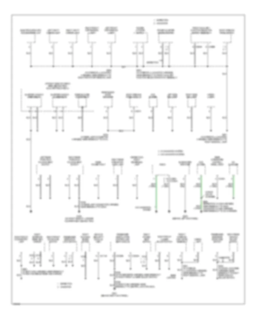
Ground Distribution Wiring Diagram (3 of 4) for Ford Expedition 2003
 https://portal-diagnostov.com/license.html
Automotive Electricians Portal FZCO
Automotive Electricians Portal FZCO
https://portal-diagnostov.com/license.html
https://portal-diagnostov.com/license.html
Automotive Electricians Portal FZCO
Automotive Electricians Portal FZCOList of elements for Ground Distribution Wiring Diagram (3 of 4) for Ford Expedition 2003:
- (expedition) left reversing lamp
- (expedition) liftgate glass release switch
- (memory) exterior rear view mirror switch
- (navigator)
- Adjustable pedal switch
- Air suspension module
- Breakout to data link connector) (navigator: in main harness, near breakout to g202)
- C2131a
- C220b
- C228a
- C294c
- C310a
- C3184b
- C341c
- C4014b
- C402b
- C4174b
- C504b
- Dirver seat module
- Driver safety belt buckle switch
- Driver side door lock switch
- Driver side front power window motor
- Eatc
- Electronic automatic temperature control (eatc) module
- Electronic compass
- Expedition
- Expedition w/ memory
- Exterior rear view mirror switch
- Four-wheel drive control module
- From s316 (diagram 2 of 4)
- Front function selector switch assembly
- G301 (behind left kick panel)
- G401 (on left side of luggage compartment, behind trim)
- G402 (on left side of luggage compartment, behind trim)
- G500 (on bottom of left front door, behind trim)
- G600 (on bottom of right front door, behind trim)
- High mounted stoplamp
- Instrument cluster
- Key pad switch assembly
- Left exterior rear view mirror
- Left front door ajar switch
- Left front door entry lamp
- Left license plate lamp
- Left power seat switch
- Left rear park/stop/ turn lamp
- Left reversing lamp
- Left tail lamp
- Liftgate chime module
- Liftgate fork bolt/detent switch
- Liftgate galss release switch
- Liftgate glass actuator
- Liftgate home position switch
- Manual a/c
- Master window adjust switch
- Memory set switch
- Navigator
- Nca
- Parking aid module (pam)
- Passenger safety belt buckle switch
- Passive anti-theft transceiver
- Power liftgate module
- Rear window defrost grid
- Rear wiper motor assembly
- Restraints control module
- Right license plate lamp
- Right reversing lamp
- Right tail lamp
- S346 (in body main harness, near breakout to g301)
- S414 (in rear lamp connector harness, near breakout to g401)
- S415 (in rear license plate lamp harness, near breakout to right license plate lamp)
- S501 (in body main harness, near breakout to left exterior rear view mirror)
- S506 (in left front door harness, near breakout to driver's side front power window motor)
- Sunload sensor
- Thermostatic expansion valve switch assembly
- W/ power folding mirror
- W/ power liftgate
- W/o memory
- W/o power folding mirror
- Windshield wiper motor
Ground Distribution Wiring Diagram (4 of 4) for Ford Expedition 2003
 https://portal-diagnostov.com/license.html
Automotive Electricians Portal FZCO
Automotive Electricians Portal FZCO
https://portal-diagnostov.com/license.html
https://portal-diagnostov.com/license.html
Automotive Electricians Portal FZCO
Automotive Electricians Portal FZCOList of elements for Ground Distribution Wiring Diagram (4 of 4) for Ford Expedition 2003:
- (at right side of cargo area, behind trim) auxiliary relay box 2
- (expedition) right reversing lamp
- Base lighting
- C2113a
- C2188a
- C290a
- C3036a
- C3036b
- C349a
- C921a d
- C989a
- C989b
- Cargo lamp
- Cd changer
- Dvd player
- Electrochromatic inside mirror unit
- Expedition
- Front auxiliary function selector switch assembly
- Front interior/ map lamps assembly
- G201 (behind right kick panel)
- G202 (behind left kick panel)
- G404 (on right side of luggage compartment, behind trim)
- Left front map reading lamp
- Left rear third row folding seat switch
- Left side rail lamp
- Left vanity mirror lamp
- Navigator
- Nca
- Passenger side climate controlled seat module
- Passenger side door lock switch
- Passenger side rear door ajar switch
- Power liftgate switch
- Power quarter window switch
- Quarter window close relay
- Quarter window open relay
- Radio
- Rear blend door actuator
- Rear blower motor relay
- Rear integrated control panel (ricp)
- Rear power point
- Right exterior rear view mirror
- Right front door ajar switch
- Right front door entry lamp
- Right front lumbar adjust switch
- Right front map reading lamp
- Right power seat switch
- Right rear park/stop/ turn lamp
- Right rear third row folding seat switch
- Right rear window adjust switch
- Right running board motor
- Right side rail lamp
- Right vanity mirror lamp
- Roof opening panel module
- Roof opening panel switch
- S290 (expedition: in main harness, near breakout to g202) (navigator: in main harness, near breakout to cd changer)
- S424 (in rear lamp connector harness, near breakout to c410)
- S436 (in rear lamp connector harness, near breakout to g404)
- S901 (in interior illumination harness, near breakout to right side rail lamp)
- S904 (in interior illumination harness, near breakout to front auxiliary function selector switch assembly)
- S906 (in interior illumination harness, near breakout to right front map reading lamp)
- Subwoofer amplifier
- To right front lumbar adjust switch)
- Vehicle security module (vsm)
- W/ navigation system
- W/ ricp, w/o cd changer
- W/o navigation system
HEADLIGHTS
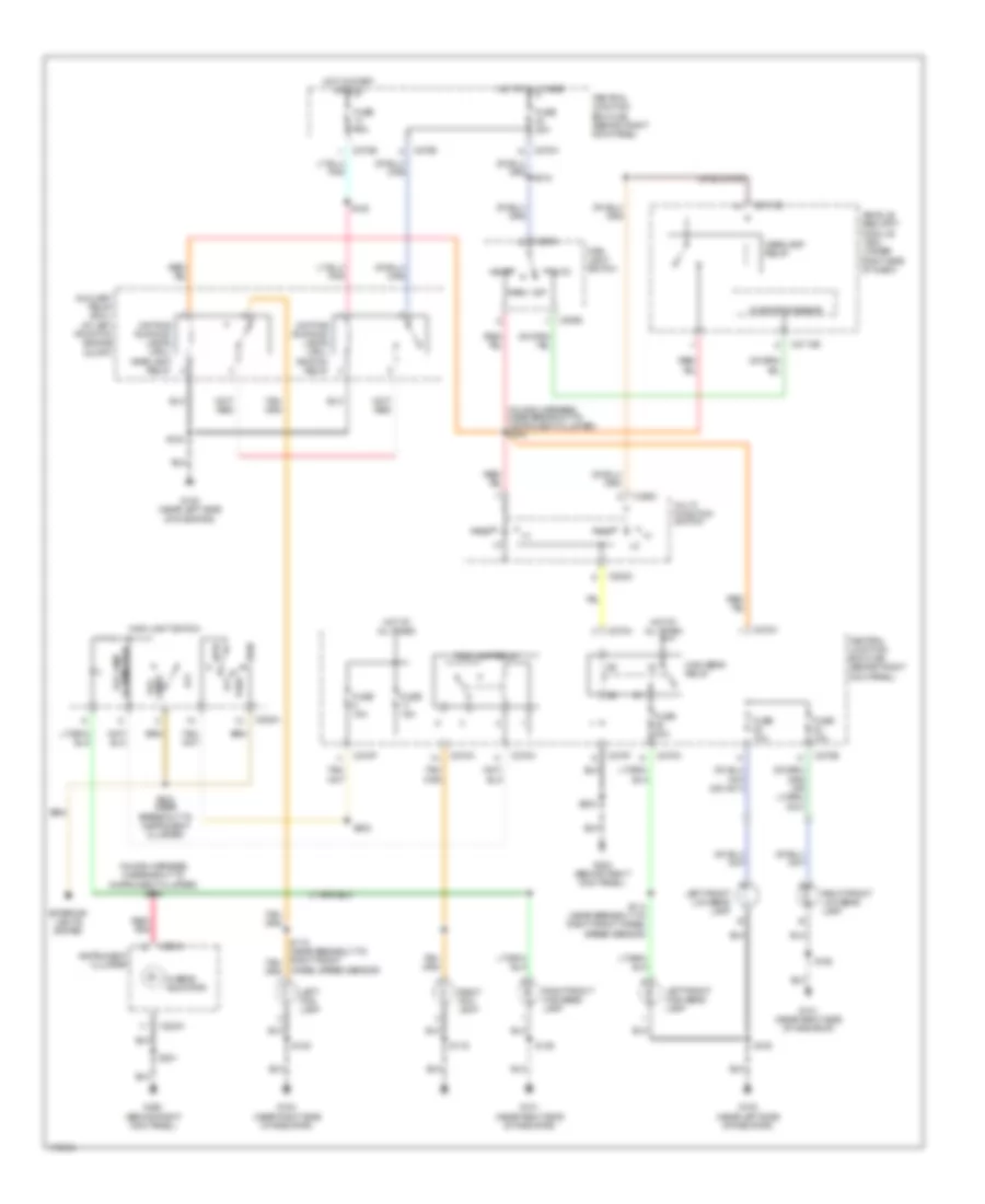
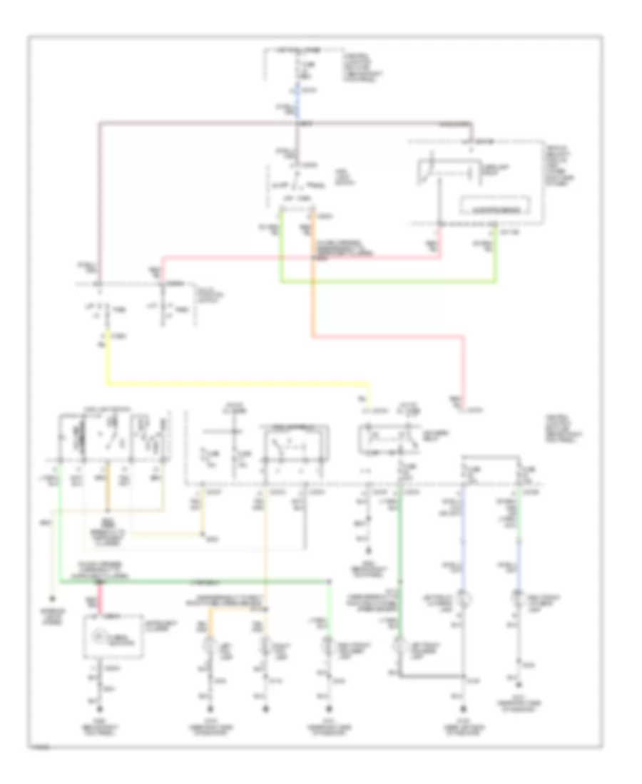
Headlights Wiring Diagram, with DRL for Ford Expedition 2003
 https://portal-diagnostov.com/license.html
Automotive Electricians Portal FZCO
Automotive Electricians Portal FZCO
https://portal-diagnostov.com/license.html
https://portal-diagnostov.com/license.html
Automotive Electricians Portal FZCO
Automotive Electricians Portal FZCOList of elements for Headlights Wiring Diagram, with DRL for Ford Expedition 2003:
- (in main harness, in breakout to instrument cluster) s266
- (in main harness, near breakout to instrument cluster) s244
- Auto
- Auxiliary relay box 1 (at left front of engine compt)
- C202c
- C205a
- C2113b
- C220a
- C270a
- C270b
- C270d
- C270f
- C270h
- Central junction box (cjb) (behind right kick panel)
- Daytime running lamps (drl) headlamp relay
- Daytime running lamps (drl) ignition relay
- Exterior lights system
- Fog lamp relay
- Fog lamps
- Fuse 10a
- Fuse 15a
- Fuse 20a
- G100 (near left side of radiator)
- G100 (near right side of radiator)
- G101 (near right side of radiator)
- G200 (behind right kick panel)
- Head
- Headlamp relay
- Hi-beam indicator
- High beam relay
- Hot at all times
- Hot in start or run
- Illumination fog lamp
- Instrument cluster
- Left fog lamp
- Left front high beam lamp
- Left front low beam lamp
- Main light switch
- Microprocessor
- Multi- function switch
- Off
- Park
- Pass
- Red/ pnk
- Right fog lamp
- Right front high beam lamp
- Right front low beam lamp
- S100
- S114 (near breakout to right front wheel speed sensor)
- S116
- S122
- S135
- S136
- S201
- S203
- S224 (near breakout to instrument cluster)
- Vehicle security module (vsm) (under right side of dash)
- Wheel speed sensor)
Headlights Wiring Diagram, without DRL for Ford Expedition 2003
 https://portal-diagnostov.com/license.html
Automotive Electricians Portal FZCO
Automotive Electricians Portal FZCO
https://portal-diagnostov.com/license.html
https://portal-diagnostov.com/license.html
Automotive Electricians Portal FZCO
Automotive Electricians Portal FZCOList of elements for Headlights Wiring Diagram, without DRL for Ford Expedition 2003:
- (in main harness, in breakout to instrument cluster) s266
- (in main harness, near breakout to instrument cluster) s244
- (near breakout to right front wheel speed sensor) s115
- Auto
- C202a
- C202c
- C205a
- C2113b
- C220a
- C270a
- C270b
- C270f
- C270h
- Central junction box (cjb) (behind right kick panel)
- Exterior lights system
- Fog lamp relay
- Fog lamps
- Fuse 10a
- Fuse 15a
- Fuse 20a
- G100 (near left side of radiator)
- G100 (near right side of radiator)
- G101 (near right side of radiator)
- G200 (behind right kick panel)
- Head
- Headlamp relay
- Hi-beam indicator
- High beam relay
- Hot at all times
- Illumination fog lamp
- Instrument cluster
- Left fog lamp
- Left front high beam lamp
- Left front low beam lamp
- Main light switch
- Microprocessor
- Multi- function switch
- Off
- Park
- Pass
- Red/ pnk
- Right fog lamp
- Right front high beam lamp
- Right front low beam lamp
- S100
- S114 (near breakout to right front wheel speed sensor)
- S116
- S135
- S136
- S201
- S203
- S212
- S224 (near breakout to instrument cluster)
- Vehicle security module (vsm) (under right side of dash)
HORN
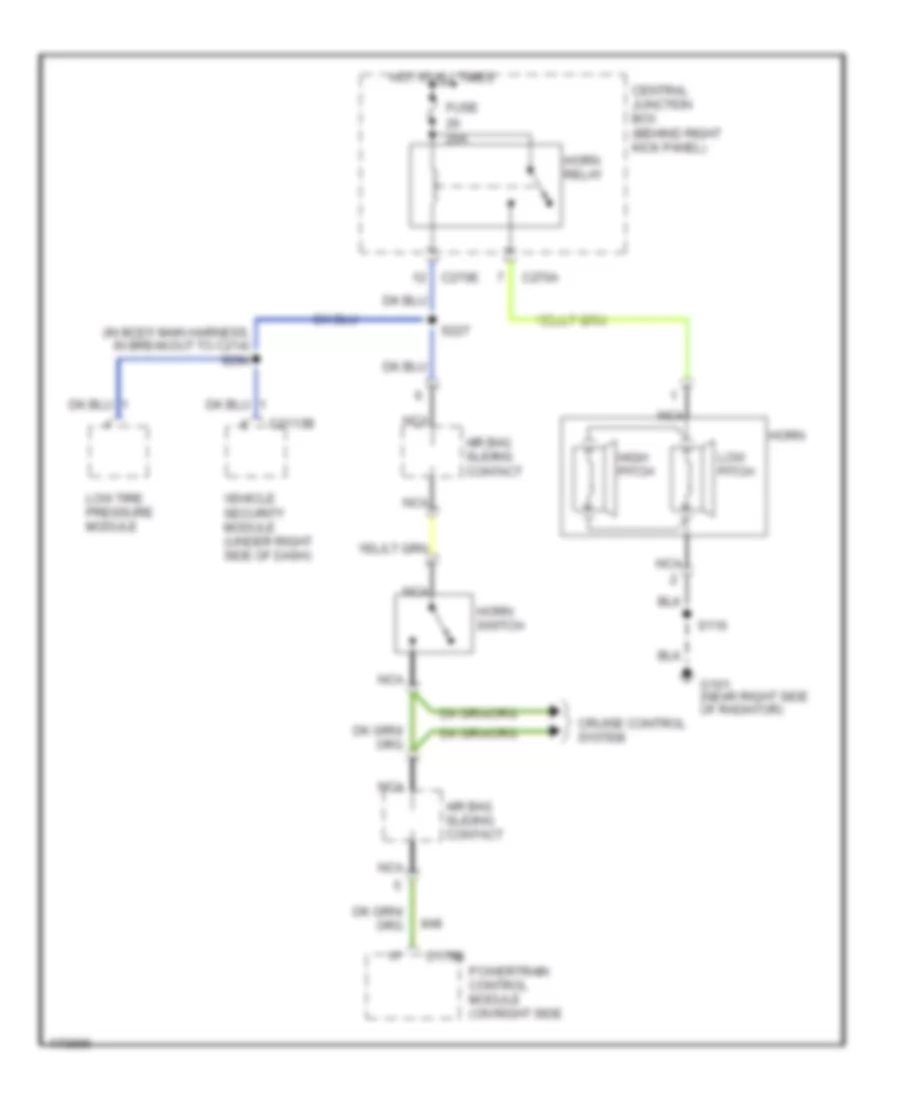
Horn Wiring Diagram for Ford Expedition 2003
 https://portal-diagnostov.com/license.html
Automotive Electricians Portal FZCO
Automotive Electricians Portal FZCO
https://portal-diagnostov.com/license.html
https://portal-diagnostov.com/license.html
Automotive Electricians Portal FZCO
Automotive Electricians Portal FZCOList of elements for Horn Wiring Diagram for Ford Expedition 2003:
- (in body main harness, in breakout to c214) s294
- (near right side of radiator)
- 20a
- Air bag sliding contact
- C175b powertrain control module (on right side
- C2113b
- C270a
- C270e
- Central junction box (behind right kick panel)
- Cruise control system
- Fuse
- G101
- High pitch
- Horn
- Horn relay
- Horn switch
- Hot at all times
- Low pitch
- Low tire pressure module
- Nca
- S116
- S227
- Vehicle security module (under right side of dash)
INSTRUMENT CLUSTER
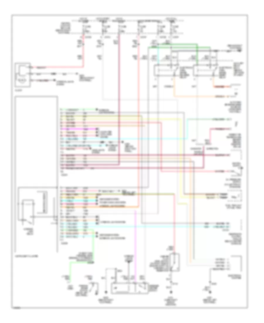
Instrument Cluster Wiring Diagram for Ford Expedition 2003
 https://portal-diagnostov.com/license.html
Automotive Electricians Portal FZCO
Automotive Electricians Portal FZCO
https://portal-diagnostov.com/license.html
https://portal-diagnostov.com/license.html
Automotive Electricians Portal FZCO
Automotive Electricians Portal FZCOList of elements for Instrument Cluster Wiring Diagram for Ford Expedition 2003:
- (behind left kick panel)
- (behind right kick panel)
- (in body main harness, near breakout to parking brake switch) s362
- (not used)
- Ambient air temperature sensor (behind radiator grille)
- Auto park brake release solenoid (at driver's footwell)
- Auxiliary relay box 3 (behind left side of dash)
- C220a
- C220b
- C270e
- C270f
- C270j
- C310a
- Central junction box (cjb) (behind right kick panel)
- Clock
- Computer data lines system
- Defogger system
- Electronic compass
- Electronic park brake release relay
- Electronic park brake reset relay
- Expedition
- Exterior lights system
- Fuel tank unit (in fuel tank)
- Fuse 10a
- Fuse 15a
- Fuse 5a
- Fuse 7.5a
- G101 (near right side of radiator)
- G200
- G200 (behind right kick panel)
- G301
- G301 (behind left kick panel)
- Headlights system
- Hot at all times
- Hot in run or acc
- Hot in start or run
- Ignition switch
- Instrument cluster
- Interior lamp relay
- Interior lights ststem
- Interior lights system
- Message center switch
- Microprocessor
- Navigator
- Nca
- Oil pressure switch (on left front of engine)
- Parking brake switch (above left kick panel)
- Power windows system
- Red/pnk
- Restraints control module (below center console)
- S116
- S201
- S202
- S208
- S228
- S238
- S277
- S282
- S308
- S318
- Washer fluid level switch (on right side of engine compt, on washer fluid reservoir)
INTERIOR LIGHTS
Courtesy Lamps Wiring Diagram for Ford Expedition 2003
 https://portal-diagnostov.com/license.html
Automotive Electricians Portal FZCO
Automotive Electricians Portal FZCO
https://portal-diagnostov.com/license.html
https://portal-diagnostov.com/license.html
Automotive Electricians Portal FZCO
Automotive Electricians Portal FZCOList of elements for Courtesy Lamps Wiring Diagram for Ford Expedition 2003:
- (in interior illumination harness, near breakout
- (in interior illumination harness, near breakout to right side rail lamp) s902
- (near breakout
- (near breakout to g301) s355
- (near breakout to left side rail lamp)
- (near breakout to left side rail lamp) s900
- (on right side of luggage compt, behind trim) g404
- A base expedition
- B all others
- Battery saver relay
- C205b
- C220b
- C270b
- C270e
- C270f
- C270j
- Cargo lamp
- Central junction box (behind right kick panel)
- Defeat
- Engine compartment lamp (expedition, early production)
- Front interior/ map lamps assembly
- Fuse 15a
- G100 (near left side of radiator)
- G200 (behind right kick panel)
- G201 (behind right kick panel)
- G300 (on left ``b" pillar, behind trim)
- Glove box lamp
- Hot at all times
- Instrument cluster
- Interior
- Interior lamp relay
- Lamp
- Left exterior rear view mirror
- Left front door entry lamp (navigator)
- Left front map reading lamp
- Left side rail lamp
- Left vanity mirror lamp
- Main light switch
- Microprocessor
- Nca
- Off
- On with any door open
- Puddle
- Puddle lamp
- Right exterior rear view mirror
- Right front door entry lamp (navigator)
- Right front map reading lamp
- Right side rail lamp
- Right vanity mirror lamp
- S104
- S201
- S203
- S238
- S424
- S501
- S600
- S900
- S901
- S901 (near breakout to right side rail lamp)
- S906 (in interior illumination harness, near breakout
- To g201) s345
- To right front map reading lamp)
- To right front map reading lamp) s907
- To right vanity mirror lamp) s905
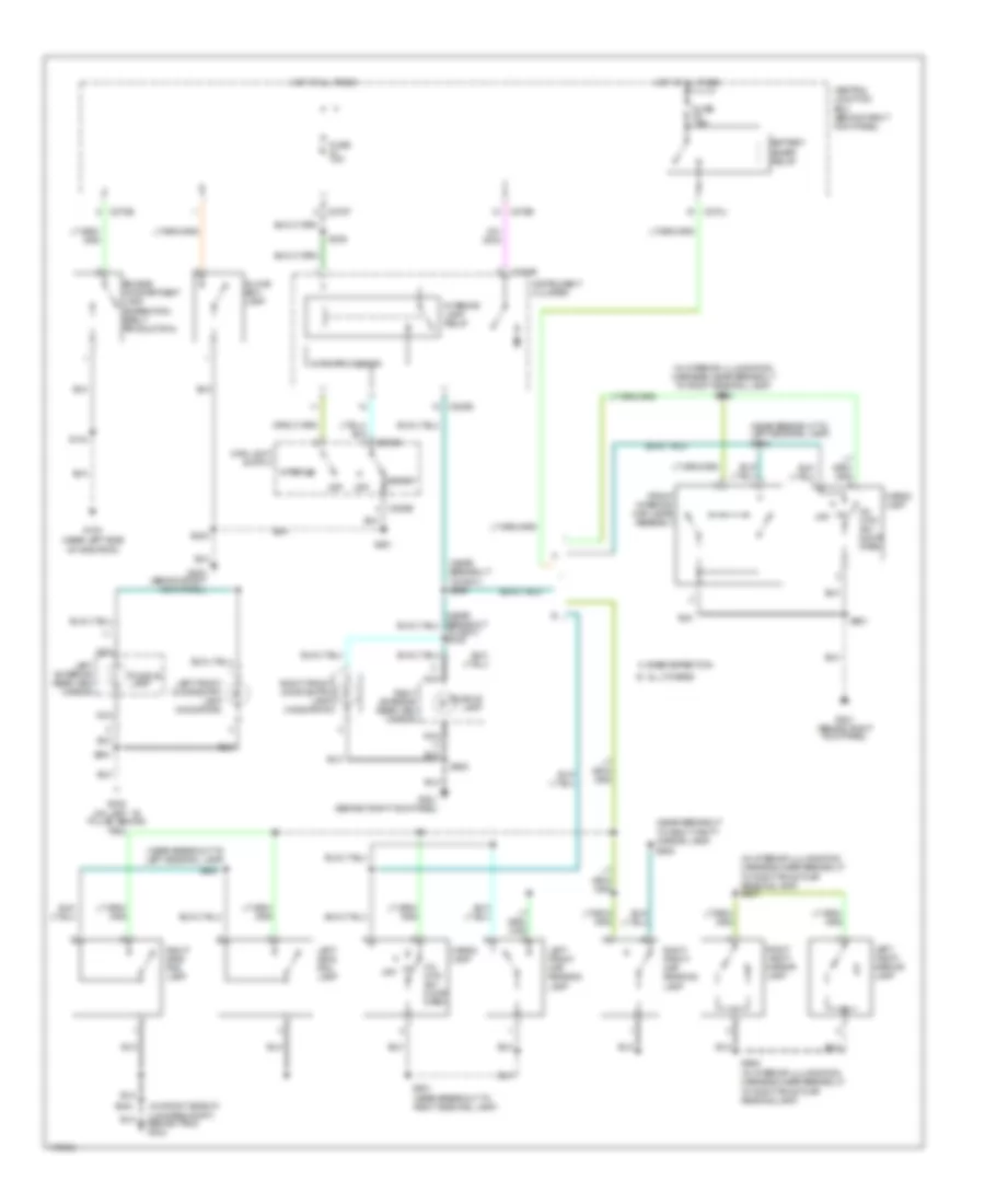
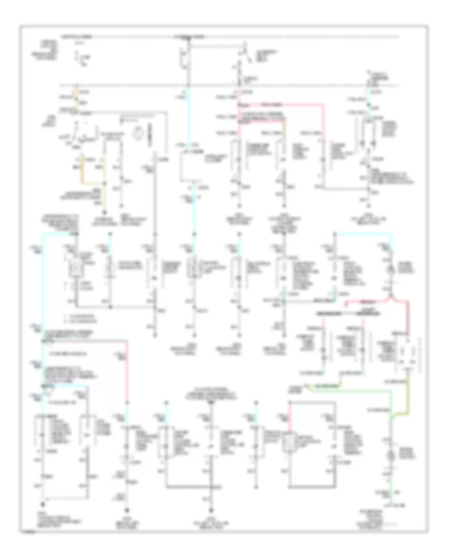
Instrument Illumination Wiring Diagram for Ford Expedition 2003
 https://portal-diagnostov.com/license.html
Automotive Electricians Portal FZCO
Automotive Electricians Portal FZCO
https://portal-diagnostov.com/license.html
https://portal-diagnostov.com/license.html
Automotive Electricians Portal FZCO
Automotive Electricians Portal FZCOList of elements for Instrument Illumination Wiring Diagram for Ford Expedition 2003:
- (behind left kick panel)
- (in body main harness, near breakout to c800) s324
- (in console panel harness, near breakout to console 2 power point) s350
- (near breakout to trailer electronic brake control connector) s242
- (on left ``b" pillar, behind trim)
- (on right side of luggage compartment, behind trim)
- Accessory delay relay
- Adjustable pedal switch
- Air bag sliding contact
- Ashtray illumination lamp
- Auto
- C175b
- C205a
- C205b
- C2188a
- C2188a c290a
- C220a
- C220b
- C228a
- C270e
- C270f
- C270n
- C290a
- C294c
- C3198b
- C349a
- C504b
- C989b
- Central junction box (behind right kick panel)
- Circuit breaker 30a
- Driver side climate controlled seat switch
- Driver side door lock switch
- Dvd player (w/ dvd player)
- Eddie bauer
- Electronic automatic temperature control module (in center of dash)
- Except eddie bauer
- Exterior lights system
- Four-wheel drive switch
- Front auxiliary function selector switch assembly
- Front function selector switch assembly (manual a/c)
- Fuse 15a
- Fuse 22 10a
- G200 (behind right kick panel)
- G201 (behind right kick panel)
- G202
- G300
- G300 (on left ``b" pillar, behind trim)
- G301 (behind left kick panel)
- G404
- G404 (on right side of luggage compartment, behind trim)
- Head
- Horns system
- Hot at all times
- Illumination
- Instrument cluster
- Main light switch
- Master window adjust switch
- Message center switch
- Nca
- Off
- Park
- Passenger side climate controlled seat switch
- Passenger side door lock switch
- Powertrain control module (on right side of firewall)
- Pulse width module
- Radio
- Rear auxiliary function selector switch assembly
- Rear integrated control panel (ricp)
- Red
- Roof opening panel switch
- S201
- S2018
- S202
- S203
- S205
- S208
- S224 (near breakout to instrument cluster)
- S290
- S361
- S370
- S501
- S506 (near breakout to driver's side front power window motor)
- S600
- S901
- S904
- Steering wheel radio switch
- Steering wheel/ speed control switch
- Traction control switch
- W/ auxiliary a/c
- W/ center console
- W/ navigation
- W/o navigation
MEMORY SYSTEMS
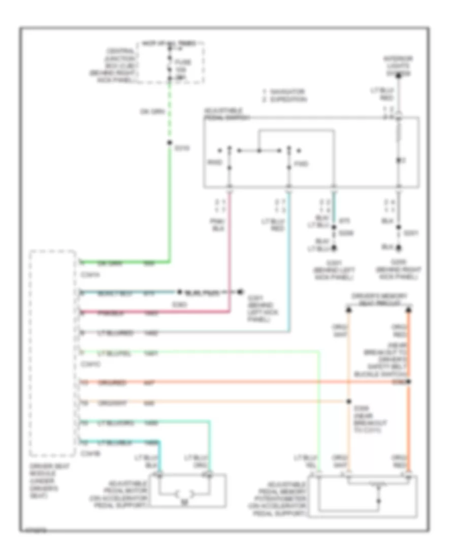
Adjustable Pedal Wiring Diagram for Ford Expedition 2003
 https://portal-diagnostov.com/license.html
Automotive Electricians Portal FZCO
Automotive Electricians Portal FZCO
https://portal-diagnostov.com/license.html
https://portal-diagnostov.com/license.html
Automotive Electricians Portal FZCO
Automotive Electricians Portal FZCOList of elements for Adjustable Pedal Wiring Diagram for Ford Expedition 2003:
- (near breakout to driver's safety belt buckle switch) s382
- Adjustable pedal memory potentiometer (on accelerator pedal support)
- Adjustable pedal motor (on accelerator pedal support)
- Adjustable pedal switch
- C341a
- C341b
- C341c
- Central junction box (cjb) (behind right kick panel)
- Driver seat module (under driver's seat)
- Driver's memory seat circuit
- Fuse 30a
- Fwd
- G200 (behind right kick panel)
- G301 (behind left kick panel)
- Hot at all times
- Interior lights system
- Navigator expedition
- Rwd
- S201
- S208
- S309 (near breakout to c311)
- S310
- S383
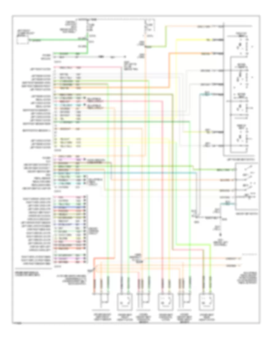
Driver"s Memory Seat Wiring Diagram for Ford Expedition 2003
 https://portal-diagnostov.com/license.html
Automotive Electricians Portal FZCO
Automotive Electricians Portal FZCO
https://portal-diagnostov.com/license.html
https://portal-diagnostov.com/license.html
Automotive Electricians Portal FZCO
Automotive Electricians Portal FZCOList of elements for Driver"s Memory Seat Wiring Diagram for Ford Expedition 2003:
- (in power seats harness, near breakout to driver's safety belt buckle switch)
- (near breakout to c311) s309
- Adjustable pedal circuit
- Adjustable pedal memory potentiometer (on accelerator pedal support)
- C270j
- C270m
- C341a
- C341b
- C341c
- C341d
- Central junction box (behind right kick panel)
- Computer data lines system
- Dlc
- Driver memory seat front height sensor
- Driver memory seat horizontal sensor
- Driver memory seat rear height sensor
- Driver seat front height motor
- Driver seat horizontal motor
- Driver seat module driver seat module (under driver's seat)
- Driver seat rear height motor
- Entire seat
- Front of seat
- Fuse 30a
- Fuse 7.5a
- Fwd
- G300 (on left "b" pillar, behind trim)
- G301 (behind left kick panel)
- Gnd
- Ground
- Hot at all times
- Left front lumbar adjust switch
- Left front motor
- Left horiz motor
- Left mirr up/dn mtr
- Left mirr up/dn pos sens
- Left mirror l/r mtr
- Left mirror posit sensor
- Left power seat switch
- Left rear motor
- Memory mirrors circuit
- Memory seat sw lamp dr
- Memory seat sw posit 1
- Memory seat sw posit 2
- Memory seat sw set
- Memory set switch
- Mirr posit sens gnd
- Mirr posit sensor feed
- Mirr sw horiz left
- Mirr sw horiz right
- Mirr sw vert left
- Mirr sw vert right
- Mirror sw common
- Nca
- Pedal backward
- Pedal forward
- Pedal motor
- Pedal sensor
- Pnk
- Power
- Rear of seat
- Red
- Right mirr l/r posit sens
- Right mirr u/d posit sens
- Right mirr up/dn mtr
- Right mirror l/r mtr
- Right mirror up/dn mtr
- Rwd
- S310
- S346
- S382
- S383
- S384
- S385
- Seat posit sensor front
- Seat posit sensor horiz
- Seat posit sensor rear
- Seat position sensor (+)
- Seat position sensor (-)
- Set
- Set 1
- Set 2
Memory Mirrors Wiring Diagram, with Power Folding Mirrors for Ford Expedition 2003
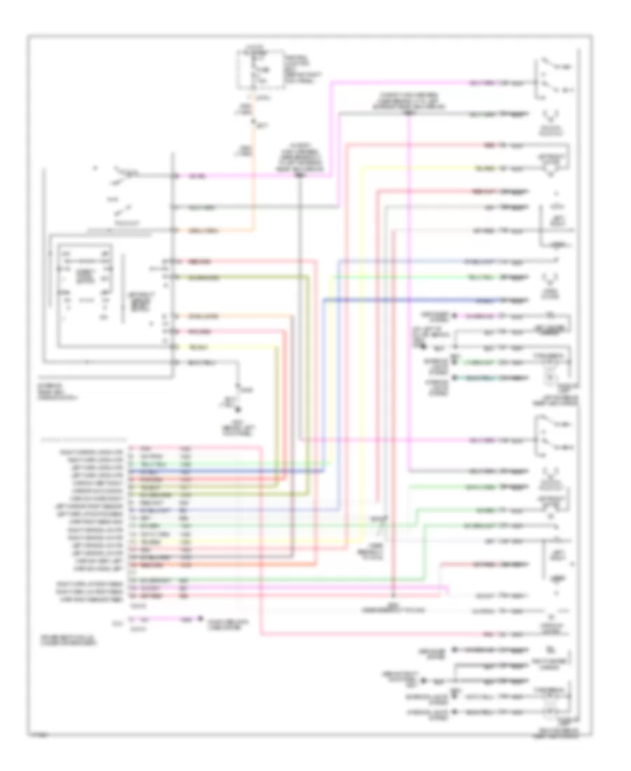 https://portal-diagnostov.com/license.html
Automotive Electricians Portal FZCO
Automotive Electricians Portal FZCO
https://portal-diagnostov.com/license.html
https://portal-diagnostov.com/license.html
Automotive Electricians Portal FZCO
Automotive Electricians Portal FZCOList of elements for Memory Mirrors Wiring Diagram, with Power Folding Mirrors for Ford Expedition 2003:
- (behind right kick panel) g201
- (in body main harness, near breakout to left exterior rear view mirror) s505
- (in body main harness, near breakout to left exterior rear view mirror) s502
- (near breakout to c316)
- (on left "b" pillar, behind trim) g300
- C270j
- C341c
- C341d
- Central junction box (behind right kick panel)
- Computer data lines system
- Defogger system
- Direct- tional switch
- Dlc
- Driver seat module (under driver's seat)
- Exterior rear view mirror switch
- Exterior lights system
- Fold in
- Fold in/ fold out
- Fold out
- Fuse 7.5a
- G301 (behind left kick panel)
- Hot at all times
- Interior lights system
- Left exterior rear view mirror
- Left heated mirror
- Left mirr up/dn mtr
- Left mirr up/dn pos sens
- Left mirror l/r mtr
- Left mirror posit sensor
- Left/ right
- Left/right mirror select switch
- Left/right motor
- Mirr posit sens gnd
- Mirr posit sensor feed
- Mirr sw horiz left
- Mirr sw horiz right
- Mirr sw vert left
- Mirr sw vert right
- Mirror sw common
- Nca
- Pnk
- Puddle lamp
- Red
- Right exterior rear view mirror
- Right heated mirror
- Right mirr l/r posit sens
- Right mirr u/d posit sens
- Right mirr up/dn mtr
- Right mirror l/r mtr
- Right mirror up/dn mtr
- S346
- S376
- S377
- S380 (near breakout to c316)
- S501
- S600
- Turn signal
- Up/dn
- Up/dn motor
- Up/down motor
Memory Mirrors Wiring Diagram, without Power Folding Mirrors for Ford Expedition 2003
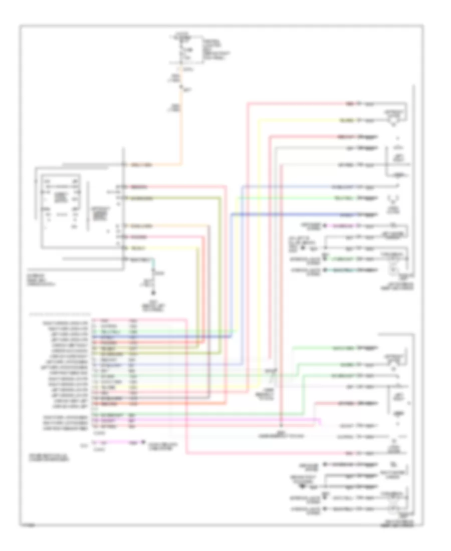 https://portal-diagnostov.com/license.html
Automotive Electricians Portal FZCO
Automotive Electricians Portal FZCO
https://portal-diagnostov.com/license.html
https://portal-diagnostov.com/license.html
Automotive Electricians Portal FZCO
Automotive Electricians Portal FZCOList of elements for Memory Mirrors Wiring Diagram, without Power Folding Mirrors for Ford Expedition 2003:
- (behind right kick panel) g201
- (near breakout to c316)
- (on left "b" pillar, behind trim) g300
- C270j
- C341c
- C341d
- Central junction box (behind right kick panel)
- Computer data lines system
- Defogger system
- Direct- tional switch
- Dlc
- Driver seat module (under driver's seat)
- Exterior rear view mirror switch
- Exterior lights system
- Fuse 7.5a
- G301 (behind left kick panel)
- Hot at all times
- Interior lights system
- Left exterior rear view mirror
- Left heated mirror
- Left mirr l/r pos sens
- Left mirr up/dn mtr
- Left mirr up/dn pos sens
- Left mirror l/r mtr
- Left/ right
- Left/right mirror select switch
- Left/right motor
- Mirr posit sens gnd
- Mirr posit sensor feed
- Mirr sw horiz left
- Mirr sw horiz right
- Mirr sw vert left
- Mirr sw vert right
- Mirror sw common
- Nca
- Pnk
- Puddle lamp
- Red
- Right exterior rear view mirror
- Right heated mirror
- Right mirr l/r pos sens
- Right mirr u/d pos sens
- Right mirr up/dn mtr
- Right mirror l/r mtr
- Right mirror up/dn mtr
- S346
- S376
- S377
- S380 (near breakout to c316)
- S501
- S600
- Turn signal
- Up/dn
- Up/dn motor
NAVIGATION
Parking Assistant Wiring Diagram for Ford Expedition 2003
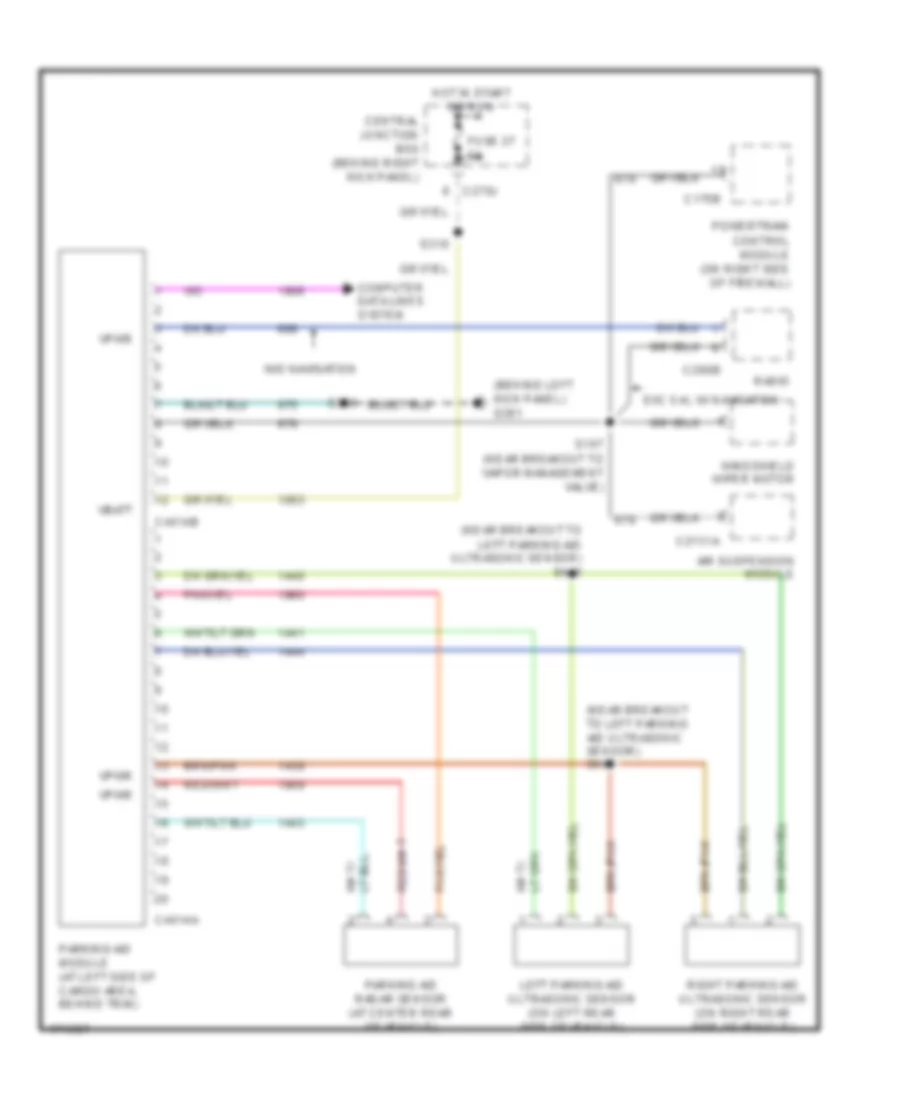 https://portal-diagnostov.com/license.html
Automotive Electricians Portal FZCO
Automotive Electricians Portal FZCO
https://portal-diagnostov.com/license.html
https://portal-diagnostov.com/license.html
Automotive Electricians Portal FZCO
Automotive Electricians Portal FZCOList of elements for Parking Assistant Wiring Diagram for Ford Expedition 2003:
- (behind left kick panel) g301
- (near breakout to left parking aid ultrasonic sensor) s440
- (near breakout to left parking aid ultrasonic sensor) s445
- Air suspension module
- C175b
- C2131a
- C270j
- C290b
- C4014a
- C4014b
- Central junction box (behind right kick panel)
- Computer data lines system
- Exc 5.4l w/ navigation
- Fuse 27 5a
- Hot in start or run
- Left parking aid ultrasonic sensor (on left rear side of vehicle)
- Parking aid module (at left side of cargo area, behind trim)
- Parking aid radar sensor (at center rear of vehicle)
- Powertrain control module (on right side of firewall)
- Radio
- Right parking aid ultrasonic sensor (on right rear side of vehicle)
- S107 (near breakout to vapor management valve)
- S318
- S346
- Vbatt
- Vpwr
- W/o navigation
- Windshield wiper motor
POWER DISTRIBUTION
Power Distribution Wiring Diagram (1 of 4) for Ford Expedition 2003
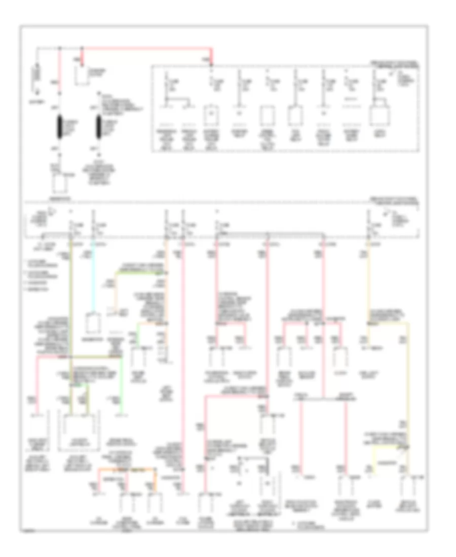 https://portal-diagnostov.com/license.html
Automotive Electricians Portal FZCO
Automotive Electricians Portal FZCO
https://portal-diagnostov.com/license.html
https://portal-diagnostov.com/license.html
Automotive Electricians Portal FZCO
Automotive Electricians Portal FZCOList of elements for Power Distribution Wiring Diagram (1 of 4) for Ford Expedition 2003:
- (behind right kick panel) central junction box
- (in body main harness, near breakout to c316) s377
- (in body main harness, near breakout to c800) s379
- (in body main harness, near breakout to central junction box) s392
- (in body main harness, near breakout to restraints control module) s372
- (in console panel harness, in breakout to c314)
- (in engine control sensor harness, near breakout to thermostatic expansion valve switch assembly) s133
- (in main harness, near breakout to glove box lamp) s203
- (in main harness, near breakout to instrument cluster) s277
- (in power seats harness, near breakout to driver's side climate controlled seat fan) s384
- (in rear lamp connector harness, near breakout to c410) s448
- (navigator: in main harness, near breakout to glove box lamp) (expedition: in main harness, near breakout to brake pedal position switch) s2001
- (not used)
- Auxiliary relay box 1 (left front of engine compt)
- Auxiliary relay box 2 (right side of cargo area, behind trim)
- Auxiliary relay box 3 (behind left side of dash)
- Battery
- Battery charge trailer tow relay
- Battery saver relay
- Brake pedal position switch
- Breakout to auxiliary relay box 1) s123
- C102b
- C175b
- C205a
- C2113b
- C228b
- C270a
- C270b
- C270e
- C270f
- C270j
- C294c
- C341c
- C349a
- C4174d
- C577 c527
- Cd changer
- Clock
- Deactivator switch
- Driver seat module
- Dvd player
- Electronic automatic temperature control (eatc) module
- Except manual a/c
- Expedition
- Exterior rear view mirror switch
- Floor shifter
- Fog lamp relay
- From a fuse 26 (diagram 1 of 4)
- Front blower motor relay
- Front function selector switch assembly
- Fuse 10a
- Fuse 15a
- Fuse 20a
- Fuse 30a
- Fuse 40a
- Fuse 7.5a
- Generator
- Horn relay
- Indicator flasher relay
- Ivd stop lamp relay
- Left power seat switch
- Left third row folding seat relay
- Main light switch
- Manual a/c
- Navigator
- Nca
- Parking lamp trailer tow relay
- Power liftgate module
- Powertrain control module (pcm)
- Rear integrated control panel (ricp)
- Red
- Reversing lamp trailer tow relay
- Right third row folding seat relay
- S1001 (in alternator rectifier system harness, in breakout to battery)
- S1002 (in alternator rectifier system harness, in breakout to battery)
- S388
- Speed control fan clutch relay
- Starter motor
- Starter relay
- Sunload sensor
- To fuse 11 (diagram 2 of 4)
- To fuse 2 (diagram 1 of 4)
- Vehicle security module (vsm)
- W/ power folding mirror
- W/ power folding seats
- W/o power folding mirror
Power Distribution Wiring Diagram (2 of 4) for Ford Expedition 2003
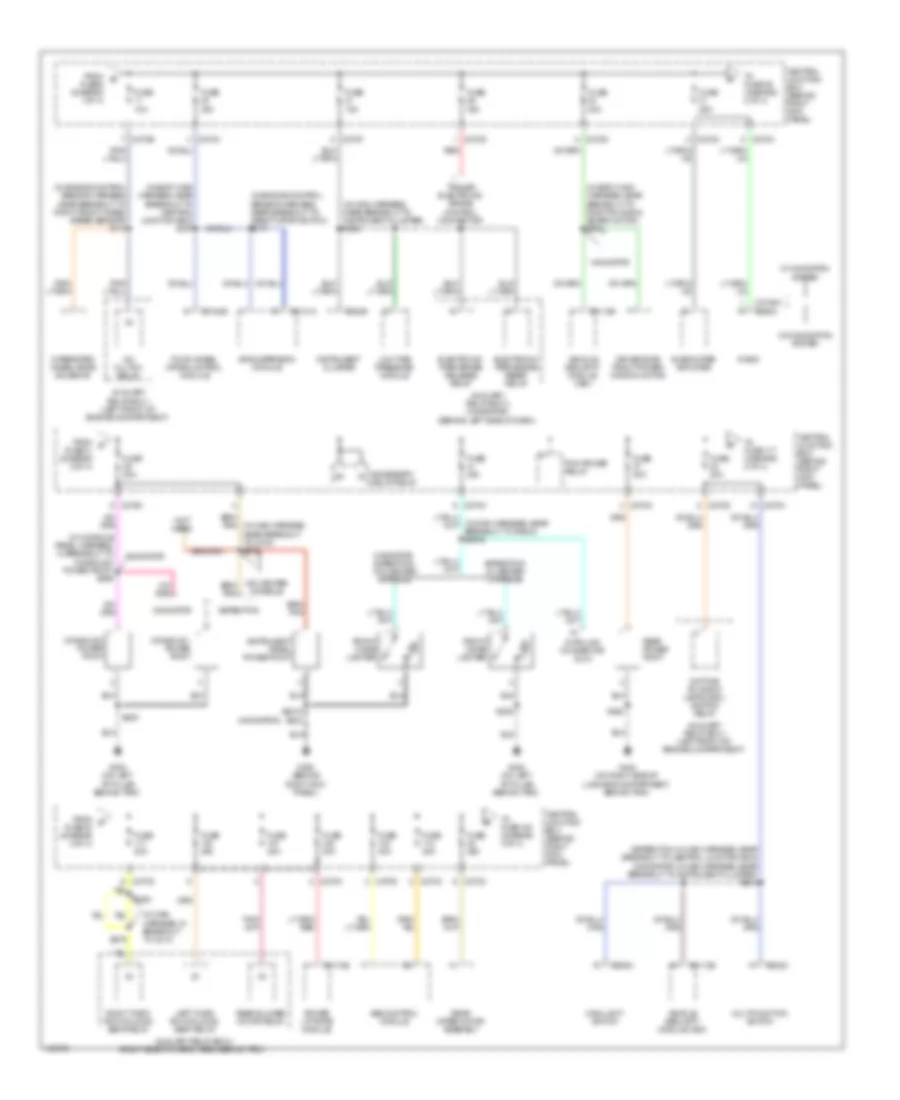 https://portal-diagnostov.com/license.html
Automotive Electricians Portal FZCO
Automotive Electricians Portal FZCO
https://portal-diagnostov.com/license.html
https://portal-diagnostov.com/license.html
Automotive Electricians Portal FZCO
Automotive Electricians Portal FZCOList of elements for Power Distribution Wiring Diagram (2 of 4) for Ford Expedition 2003:
- (expedition: in main harness, near breakout to central junction box) (navigator: in main harness, near breakout to instrument cluster) s212
- (in body main harness, near breakout to central junction box) s357
- (in body main harness, near breakout to right running board motor) s391
- (in console panel harness, in breakout to console 2 power point) s396
- (in engine control sensor harness, near breakout to deactivator switch) s117
- (in engine control sensor harness, near breakout to right front wheel speed sensor) s113
- (in main harness, in breakout to c214)
- (in main harness, near breakout to instrument cluster) s238
- (navigator)
- (not used)
- A/c clutch relay
- Abs control module
- Accessory delay relay
- Air suspension module
- Auxiliary relay box 1 (left front of engine compartment)
- Auxiliary relay box 2 (right side of cargo area, behind trim)
- Auxiliary relay box 3 (navigator) (behind left side of dash)
- C202c
- C205a
- C2113b
- C2131a
- C2188a c290a
- C220b
- C270b
- C270c
- C270d
- C270f
- C270g
- C270h
- C270k
- C270m
- C270n
- C3184b
- C4174b
- Central junction box (behind right kick panel)
- Console 1 power point
- Console 2 power point
- Data link connector (dlc)
- Daytime running lamps (drl) ignition relay
- Driver side front power window motor
- Electronic park brake release relay
- Electronic park brake reset relay
- Expedition
- Expedition w/ center console
- Four-wheel drive control module
- From b fuse 6 (diagram 1 of 4)
- From c fuse 31 (diagram 2 of 4)
- From d fuse 40 (diagram 2 of 4)
- Front cigar lighter
- Fuse 10a
- Fuse 15a
- Fuse 20a
- Fuse 25a
- Fuse 30a
- G200 (behind right kick panel)
- G300 (on left ``b" pillar, behind trim)
- G404 (on right side of luggage compartment, behind trim)
- Instrument cluster
- Instrument panel power point
- Integrated wheel ends solenoid
- Left third row folding seat relay
- Low tire pressure module
- Main light switch
- Multifunction switch
- Navigator
- Navigator, expedition w/o center console
- Pcm power relay
- Power liftgate module
- Radio
- Rear blower motor relay
- Rear power point
- Rear wiper motor assembly
- Red
- Right third row folding seat relay
- S2018
- S202
- S205
- S279
- S280
- S436
- Subwoofer amplifier
- To fuse 108 (diagram 3 of 4)
- To fuse 117 (diagram 2 of 4)
- To fuse 39 (diagram 2 of 4)
- Trailer electronic brake control connector
- Vehicle security module (vsm)
- W/ navigation system
- W/o center console
- W/o navigation system
Power Distribution Wiring Diagram (3 of 4) for Ford Expedition 2003
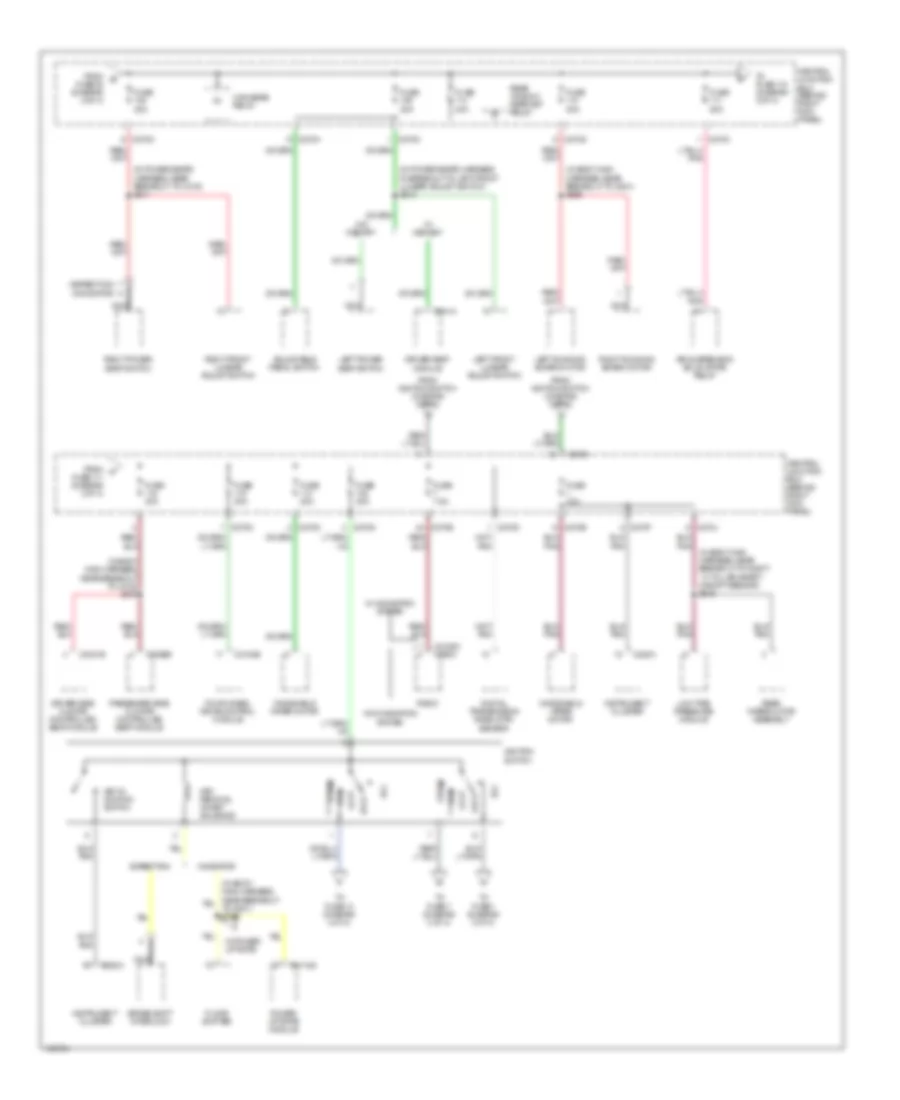 https://portal-diagnostov.com/license.html
Automotive Electricians Portal FZCO
Automotive Electricians Portal FZCO
https://portal-diagnostov.com/license.html
https://portal-diagnostov.com/license.html
Automotive Electricians Portal FZCO
Automotive Electricians Portal FZCOList of elements for Power Distribution Wiring Diagram (3 of 4) for Ford Expedition 2003:
- (expedition) a
- (in body main harness, near breakout to c316) s375
- (in body main harness, near breakout to g301) s395
- (in body main harness, near breakout to right ``c" pillar safety canopy sensor) s315
- (in power seats harness, in breakout to left front lumbar adjust switch) s310
- (in power seats harness, near breakout to c316) s311
- (navigator)
- Acc
- Adjustable pedal switch
- Air suspension solid state relay
- Brake shift interlock
- C2188c c290a
- C220a
- C270b
- C270c
- C270d
- C270e
- C270f
- C270g
- C270h
- C270j
- C270m
- C3031b
- C3036b
- C3184b
- C341a
- C4174d
- Central junction box (behind right kick panel)
- Digital transmission rane (dtr) sensor
- Driver seat module
- Driver side climate controlled seat module
- Expedition
- Floor shifter
- Four-wheel drive control module
- From e fuse 38 (diagram 2 of 4)
- From f fuse 111 (diagram 3 of 4)
- From ignition switch (diagram 3 of 4)
- Fuse 10a
- Fuse 30a
- Fuse 40a
- Fuse 50a
- Fuse 7.5a
- High beam relay
- Ignition switch
- Instrument cluster
- Key in ignition switch
- Key removal inhibit solenoid
- Left front lumbar adjust switch
- Left power seat switch
- Left running board motor
- Lock
- Low tire pressure module
- Navigator
- Nca
- Off
- Passenger side climate controlled seat module
- Power liftgate module
- Radio
- Rear window defrost relay
- Rear wiper motor assembly
- Right front lumbar adjust switch
- Right power seat switch
- Right running board motor
- Run
- Start
- To fuse 1 (diagram 3 of 4)
- To fuse 118 (diagram 3 of 4)
- To fuse 13 (diagram 4 of 4)
- To fuse 7 (diagram 3 of 4)
- W/ memory
- W/ navigation system
- W/ power liftgate
- W/o memory
- W/o navigation system
- Windshield wiper motor
Power Distribution Wiring Diagram (4 of 4) for Ford Expedition 2003
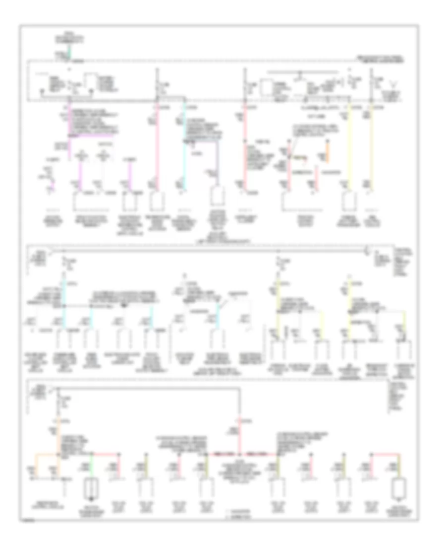 https://portal-diagnostov.com/license.html
Automotive Electricians Portal FZCO
Automotive Electricians Portal FZCO
https://portal-diagnostov.com/license.html
https://portal-diagnostov.com/license.html
Automotive Electricians Portal FZCO
Automotive Electricians Portal FZCOList of elements for Power Distribution Wiring Diagram (4 of 4) for Ford Expedition 2003:
- (behind right kick panel) central junction box
- (expedition)
- (in body main harness, near breakout to c316) s318
- (in body main harness, near breakout to c800) s319
- (in body main harness, near breakout to restraints control module) s320
- (in console panel harn, in breakout to traction control switch)
- (in engine control sensor & fuel charge harness, near breakout to heated oxygen sensor 11) s132
- (in engine control sensor & fuel charge harness, near breakout to heated oxygen sensor 21) s124
- (in interior illumination harness, near breakout to front auxiliary function selector switch assembly) s903
- (in main harness, near breakout to c210) s221
- (left front of engine compt)
- (navigator)
- A/c high pressure switch
- Abs control module
- Air suspension module
- Auxiliary relay box 1
- Auxiliary relay box 3 (behind left side of dash)
- Battery charge trailer tow relay
- Brake shift interlock
- C2131a
- C220b
- C228b
- C270b
- C270d
- C270e
- C270f
- C270g
- C270j
- C294b
- C294c
- C3031b
- C3036b
- C310a
- C4014b
- C989b
- Central junction box (behind right kick panel)
- Coil on plug (cop) 1
- Coil on plug (cop) 2
- Coil on plug (cop) 3
- Coil on plug (cop) 4
- Coil on plug (cop) 5
- Coil on plug (cop) 6
- Coil on plug (cop) 7
- Coil on plug (cop) 8
- Daytime running lamps (drl) ignition relay
- Digital transmission range (dtr) sensor
- Driver side climate controlled seat module
- Electrochromatic inside mirror unit
- Electronic automatic temperature control (eatc) module
- Electronic compass
- Electronic park brake release relay
- Electronic park brake reset relay
- Expedition
- Floor shifter (navigator)
- From fuse 27 k (diagram 4 of 4)
- From ignition switch (diagram 3 of 4)
- From j fuse 16 (diagram 4 of 4)
- Front auxiliary function selector switch assembly
- Front function selector switch assembly
- Fuse 10a
- Fuse 5a
- Harness, near breakout to c219) s228
- Ignition transformer capacitor 1
- Ignition transformer capacitor 2
- Indicator flasher relay
- Instrument cluster
- Navigator
- Nca
- Not used
- Overdrive cancel switch (expedition)
- Parking aid module (pam)
- Passenger side climate controlled seat module
- Passive anti-theft transceiver
- Pcm power diode
- Pcm power relay
- Rear blend door actuator
- Rear window defrost relay
- Restraints control module
- S129 (in engine control sensor & fuel charge harness, near breakout to coil on plug 4)
- S282 (in main harness, near breakout to instrument cluster)
- S387 (exped- ition)
- Speed control fan clutch relay
- Tan/ red
- Temperature blend door actuator
- To eatc module) (navigator: in main harness, near breakout to central junction box) s241
- To fuse 18 (diagram 4 of 4)
- To fuse 19 (diagram 4 of 4)
- Traction control switch
- W/ drl
- W/ eatc
- W/ manual a/c
POWER MIRRORS
Electronic Day/Night Mirror Wiring Diagram for Ford Expedition 2003
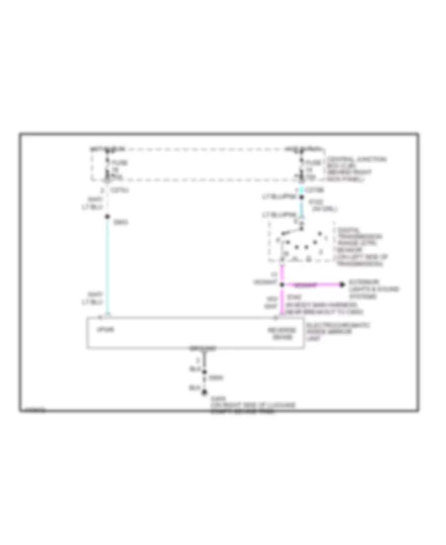 https://portal-diagnostov.com/license.html
Automotive Electricians Portal FZCO
Automotive Electricians Portal FZCO
https://portal-diagnostov.com/license.html
https://portal-diagnostov.com/license.html
Automotive Electricians Portal FZCO
Automotive Electricians Portal FZCOList of elements for Electronic Day/Night Mirror Wiring Diagram for Ford Expedition 2003:
- (in body main harness, near breakout to c800)
- (w/ drl)
- C270b
- C270j
- Central junction box (cjb) (behind right kick panel)
- Digital transmission range (dtr) sensor (on left side of transmission)
- Electrochromatic inside mirror unit
- Exterior lights & sound systems
- Fuse 10a
- G404 (on right side of luggage compt, behind trim)
- Ground
- Hot in run
- Reverse
- S122
- S342
- S903
- S906
- Sense
- Vpwr
Power Mirrors Wiring Diagram for Ford Expedition 2003
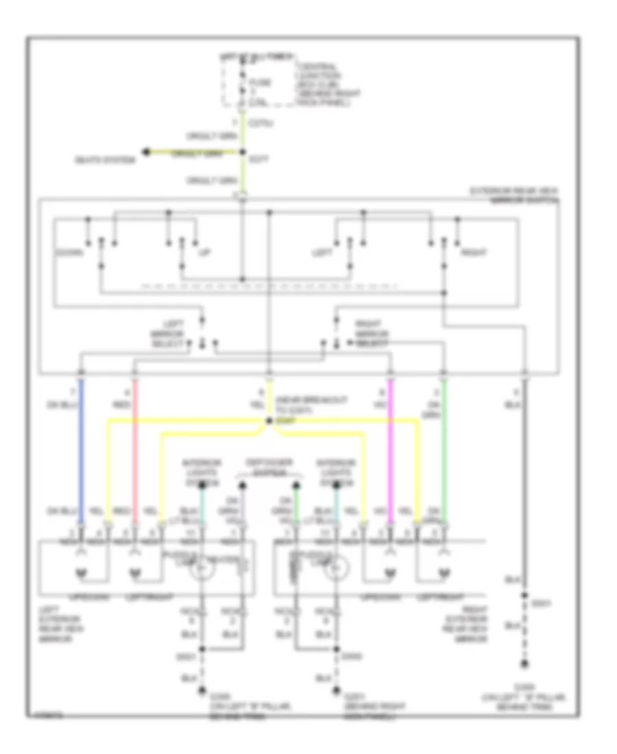 https://portal-diagnostov.com/license.html
Automotive Electricians Portal FZCO
Automotive Electricians Portal FZCO
https://portal-diagnostov.com/license.html
https://portal-diagnostov.com/license.html
Automotive Electricians Portal FZCO
Automotive Electricians Portal FZCOList of elements for Power Mirrors Wiring Diagram for Ford Expedition 2003:
- (near breakout to g301) s347
- C270j
- Central junction box (cjb) (behind right kick panel)
- Defogger system
- Down
- Exterior rear view mirror switch
- Fuse 7.5a
- G201 (behind right kick panel)
- G300 (on left "b" pillar, behind trim)
- G300 (on left ``b" pillar, behind trim)
- Heater
- Hot at all times
- Interior lights system
- Left
- Left exterior rear view mirror
- Left mirror select
- Left/right
- Nca
- Puddle lamp
- Red
- Right
- Right exterior rear view mirror
- Right mirror select
- S377
- S501
- S600
- Seats system
- Up/down
POWER SEATS
Adjustable Pedal Wiring Diagram for Ford Expedition 2003
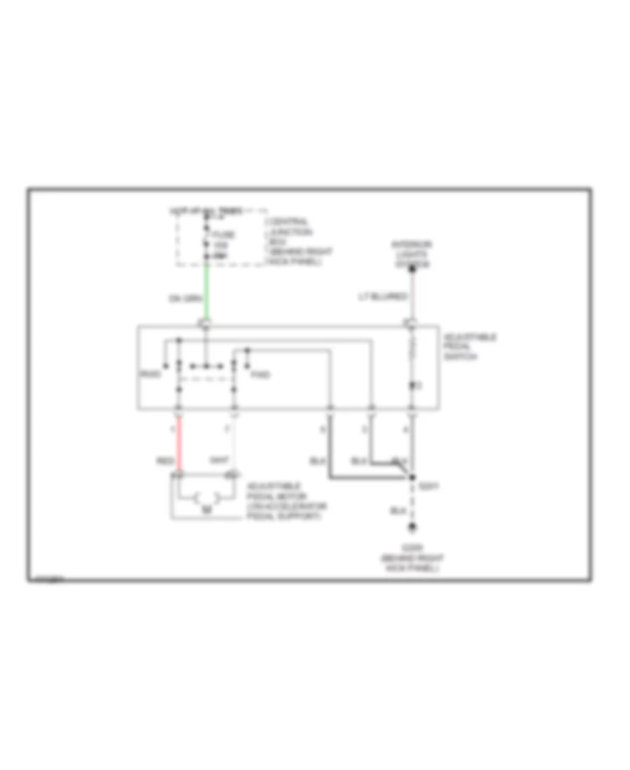 https://portal-diagnostov.com/license.html
Automotive Electricians Portal FZCO
Automotive Electricians Portal FZCO
https://portal-diagnostov.com/license.html
https://portal-diagnostov.com/license.html
Automotive Electricians Portal FZCO
Automotive Electricians Portal FZCOList of elements for Adjustable Pedal Wiring Diagram for Ford Expedition 2003:
- Adjustable pedal motor (on accelerator pedal support)
- Adjustable pedal switch
- Central junction box (behind right kick panel)
- Fuse 30a
- Fwd
- G200 (behind right kick panel)
- Hot at all times
- Interior lights system
- Red
- Rwd
- S201
Driver Power Seat Wiring Diagram for Ford Expedition 2003
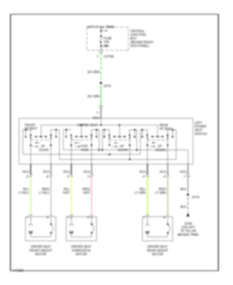 https://portal-diagnostov.com/license.html
Automotive Electricians Portal FZCO
Automotive Electricians Portal FZCO
https://portal-diagnostov.com/license.html
https://portal-diagnostov.com/license.html
Automotive Electricians Portal FZCO
Automotive Electricians Portal FZCOList of elements for Driver Power Seat Wiring Diagram for Ford Expedition 2003:
- C270m
- Central junction box (behind right kick panel)
- Driver seat front height motor
- Driver seat horizontal motor
- Driver seat rear height motor
- Entire seat
- Front of seat
- Fuse 30a
- Fwd rwd
- G300 (on left ``b" pillar, behind trim)
- Hot at all times
- Left power seat switch
- Nca
- Rear of seat
- S310
- S316
- Up down
Heated Seats Wiring Diagram for Ford Expedition 2003
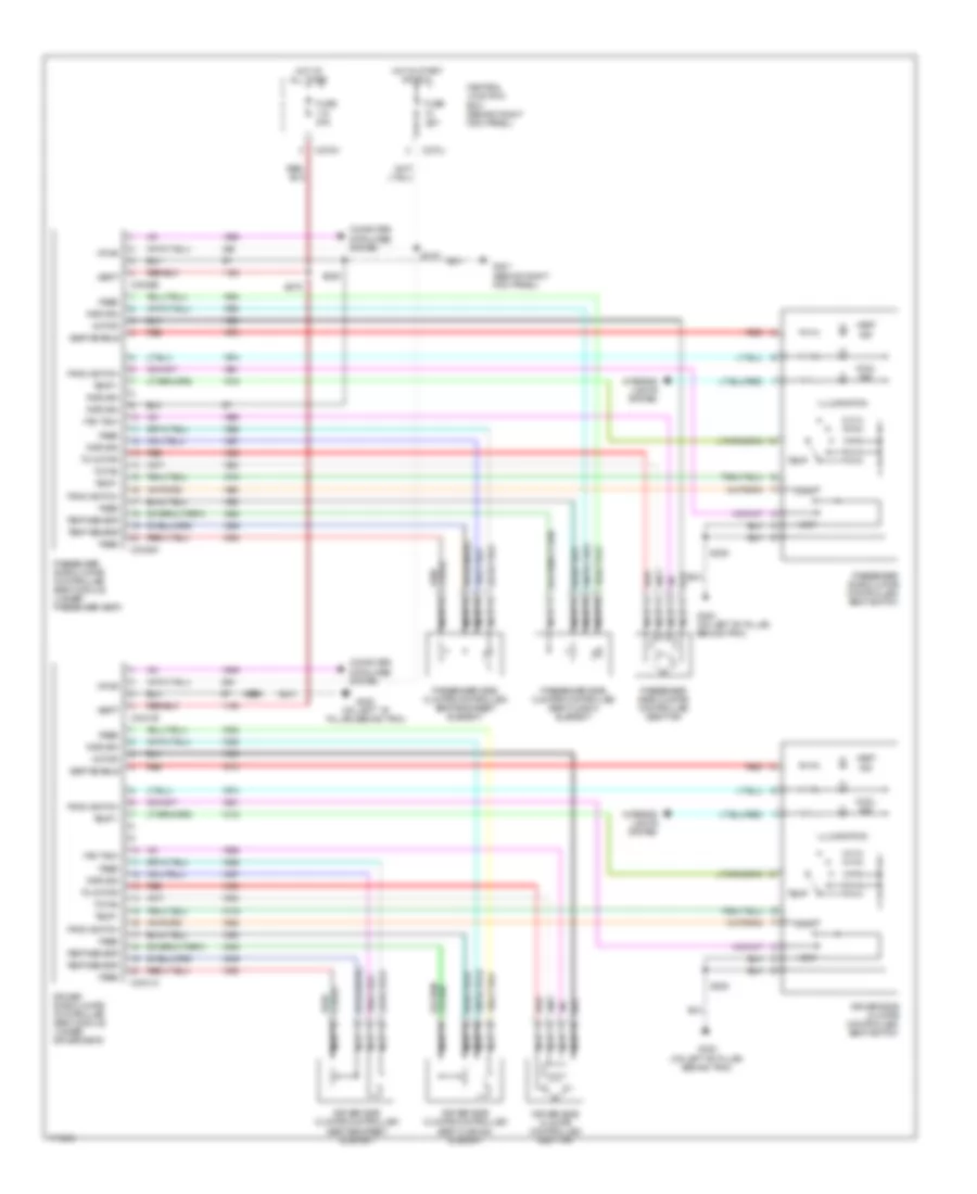 https://portal-diagnostov.com/license.html
Automotive Electricians Portal FZCO
Automotive Electricians Portal FZCO
https://portal-diagnostov.com/license.html
https://portal-diagnostov.com/license.html
Automotive Electricians Portal FZCO
Automotive Electricians Portal FZCOList of elements for Heated Seats Wiring Diagram for Ford Expedition 2003:
- C270j
- C270m
- C3031a
- C3031b
- C3036a
- C3036b
- Central junction box (behind right kick panel)
- Computer data lines system
- Cool
- Cool ind
- Driver side climate controlled seat backrest element
- Driver side climate controlled seat cushion element
- Driver side climate controlled seat fan
- Driver side climate controlled seat module (under driver seat)
- Driver side climate controlled seat switch
- Fan tach
- Feed
- From switch
- Fuse 10a
- Fuse 30a
- G201 (behind right kick panel)
- G300 (on left "b" pillar, behind trim)
- G300 (on left ``b" pillar, behind trim)
- Heat
- Heat ind
- Hot at all times
- Hot in start or run
- Illumination
- Interior lights system
- Motor
- Nca
- Passenger side climate controlled seat backrest element
- Passenger side climate controlled seat cusion element
- Passenger side climate controlled seat fan
- Passenger side climate controlled seat module (under passenger seat)
- Passenger side climate controlled seat switch
- Red
- Red/
- Return
- S205
- S319
- S329
- S375
- S385
- Seat enable
- Temp
- Temp +
- Temp -
- Temp sensor
- To fan
- To motor
- Vbatt
- Vpwr
Lumbar Wiring Diagram for Ford Expedition 2003
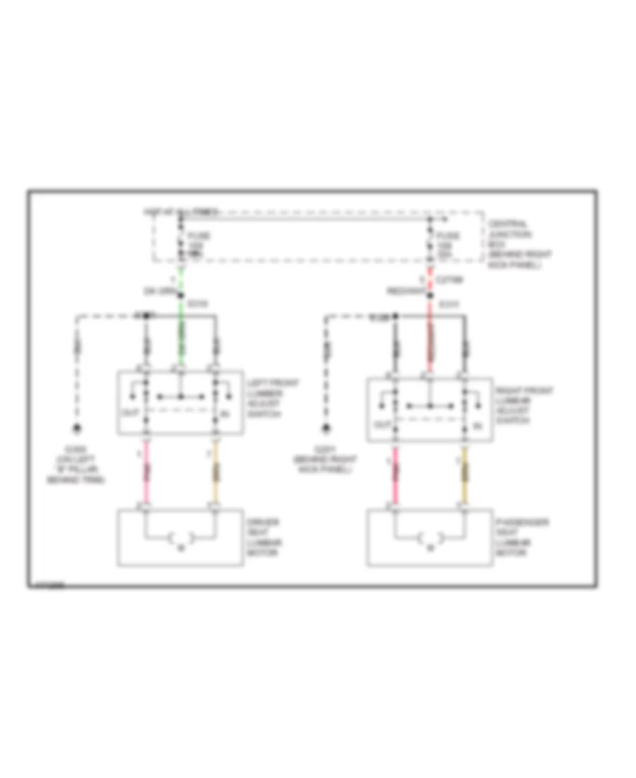 https://portal-diagnostov.com/license.html
Automotive Electricians Portal FZCO
Automotive Electricians Portal FZCO
https://portal-diagnostov.com/license.html
https://portal-diagnostov.com/license.html
Automotive Electricians Portal FZCO
Automotive Electricians Portal FZCOList of elements for Lumbar Wiring Diagram for Ford Expedition 2003:
- C270m
- Central junction box (behind right kick panel)
- Driver seat lumbar motor
- Fuse 30a
- G201 (behind right kick panel)
- G300 (on left ``b" pillar, behind trim)
- Hot at all times
- Left front lumber adjust switch
- Out
- Passenger seat lumbar motor
- Pnk
- Right front lumbar adjust switch
- S310
- S311
- S329
- S385
Passenger Power Seat Wiring Diagram for Ford Expedition 2003
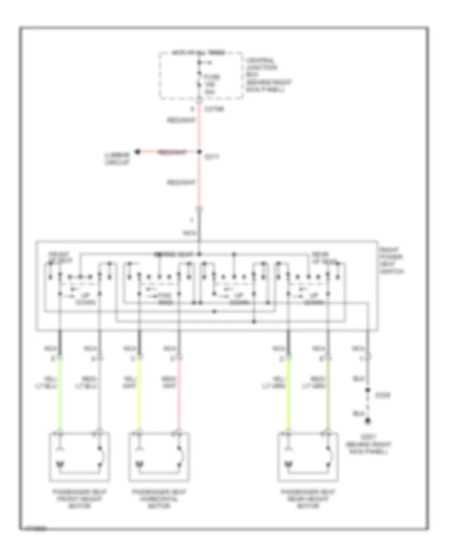 https://portal-diagnostov.com/license.html
Automotive Electricians Portal FZCO
Automotive Electricians Portal FZCO
https://portal-diagnostov.com/license.html
https://portal-diagnostov.com/license.html
Automotive Electricians Portal FZCO
Automotive Electricians Portal FZCOList of elements for Passenger Power Seat Wiring Diagram for Ford Expedition 2003:
- C270m
- Central junction box (behind right kick panel)
- Down
- Entire seat
- Front of seat
- Fuse 30a
- Fwd rwd
- G201 (behind right kick panel)
- Hot at all times
- Lumbar circuit
- Nca
- Passenger seat front height motor
- Passenger seat horizontal motor
- Passenger seat rear height motor
- Rear of seat
- Right power seat switch
- S311
- S329
Third Row Folding Seat Wiring Diagram for Ford Expedition 2003
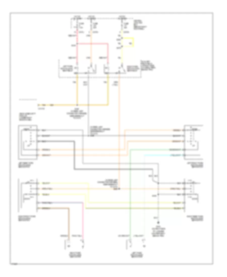 https://portal-diagnostov.com/license.html
Automotive Electricians Portal FZCO
Automotive Electricians Portal FZCO
https://portal-diagnostov.com/license.html
https://portal-diagnostov.com/license.html
Automotive Electricians Portal FZCO
Automotive Electricians Portal FZCOList of elements for Third Row Folding Seat Wiring Diagram for Ford Expedition 2003:
- (in rear lamp connector harness, near breakout to c410) s468
- (in rear lamp connector harness, near breakout to c410) s469
- (on right side
- Auxiliary relay box 2 (at right side of cargo area, behind trim)
- Behind trim)
- C2113c
- C270g
- C270j
- C270n
- Central junction box (behind right kick panel)
- Compartment,
- Connector harness,
- Down
- Fuse 30a
- Fuse 7.5a
- G404
- Hot at all times
- Left front third row folding seat switch
- Left rear third row folding seat switch
- Left third row folding seat motor
- Left third row folding seat relay
- Near breakout to c410)
- Of luggage
- Right front third row folding seat switch
- Right rear third row folding seat switch
- Right third row folding seat motor
- Right third row folding seat relay
- S279
- S280
- S436
- S448
- S449 (in rear lamp
- Tan
- Vehicle security module (under right side of dash)
POWER TOP/SUNROOF
Power Top/Sunroof Wiring Diagram for Ford Expedition 2003
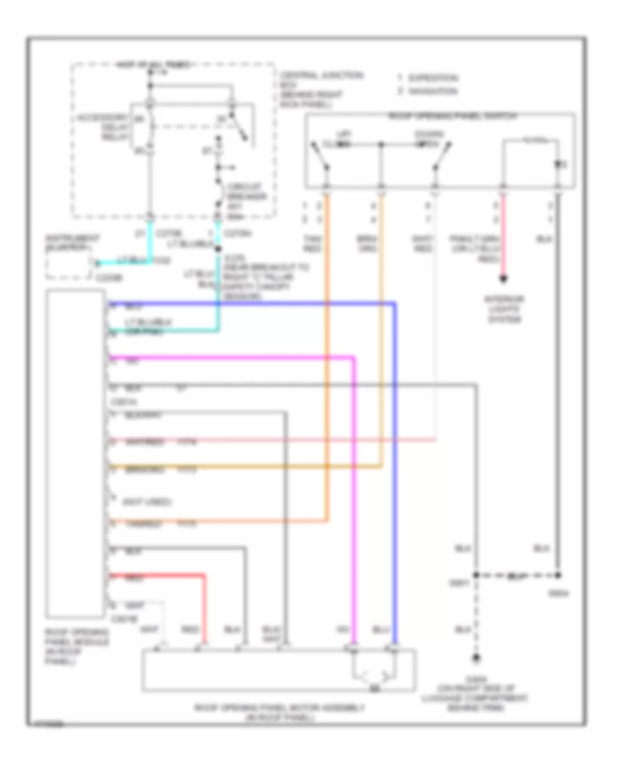 https://portal-diagnostov.com/license.html
Automotive Electricians Portal FZCO
Automotive Electricians Portal FZCO
https://portal-diagnostov.com/license.html
https://portal-diagnostov.com/license.html
Automotive Electricians Portal FZCO
Automotive Electricians Portal FZCOList of elements for Power Top/Sunroof Wiring Diagram for Ford Expedition 2003:
- (not used)
- Accessory delay relay
- C220b
- C270e
- C921a
- C921b
- Central junction box (behind right kick panel)
- Circuit breaker 30a
- Down/ open
- Expedition
- G404 (on right side of luggage compartment, behind trim)
- Hot at all times
- Instrument cluster
- Interior lights system
- Navigation
- Red
- Roof opening panel module (in roof panel)
- Roof opening panel motor assembly (in roof panel)
- Roof opening panel switch
- S370 (near breakout to right "c" pillar safety canopy sensor)
- S901
- S904
- Tan/ red
- Tan/red
- Up/ close
POWER WINDOWS
Power Windows Wiring Diagram for Ford Expedition 2003
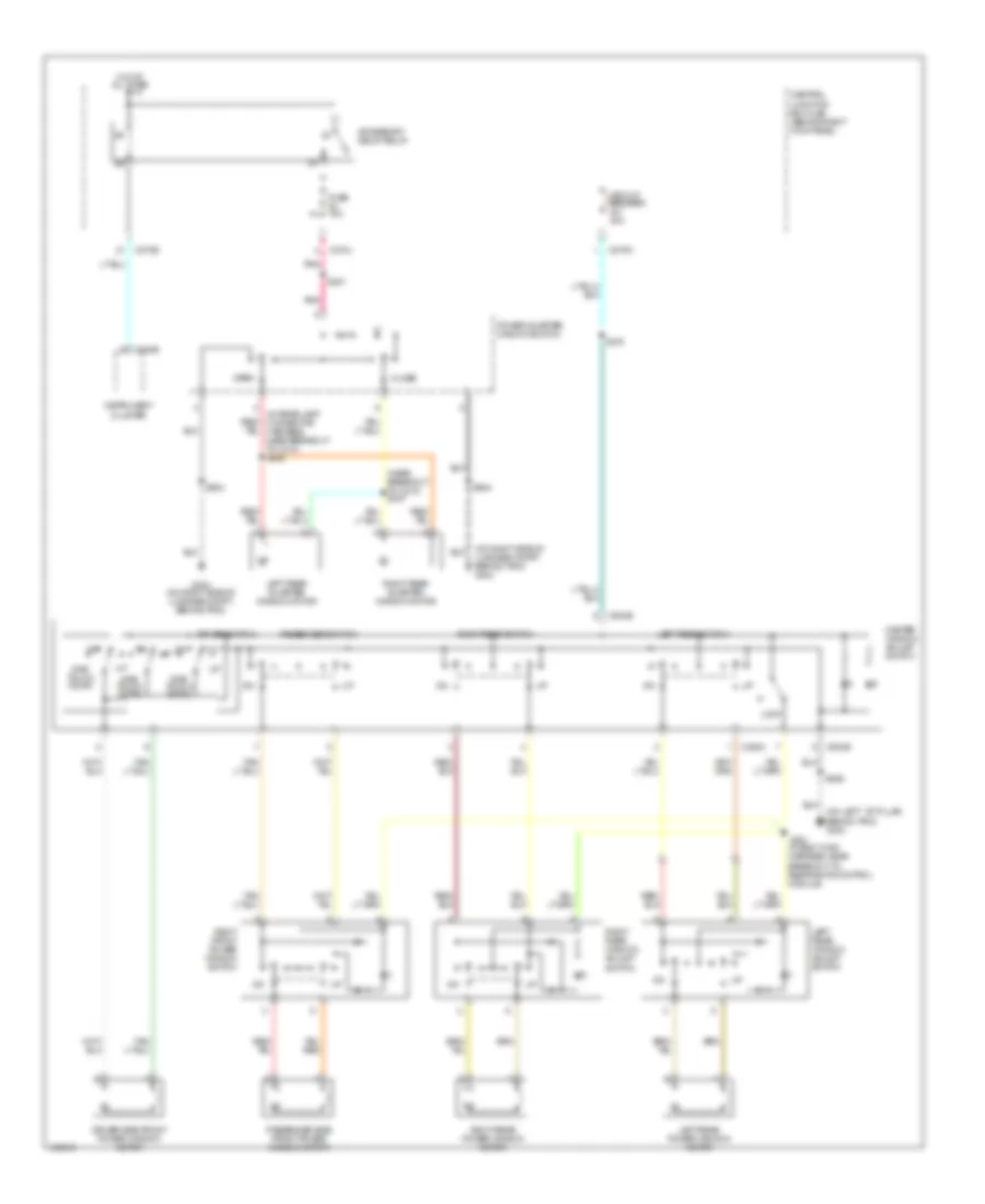 https://portal-diagnostov.com/license.html
Automotive Electricians Portal FZCO
Automotive Electricians Portal FZCO
https://portal-diagnostov.com/license.html
https://portal-diagnostov.com/license.html
Automotive Electricians Portal FZCO
Automotive Electricians Portal FZCOList of elements for Power Windows Wiring Diagram for Ford Expedition 2003:
- (in body main harness, near breakout to restraints control module)
- (in rear lamp connector harness, near breakout to c410) s446
- (near breakout to c410) s447
- (on left ``b" pillar, behind trim) g300
- (on right side of luggage compt, behind trim) g404
- Accessory delay relay
- C220b
- C270e
- C270j
- C270n
- C504a
- C504b
- Central junction box (cjb) (behind right kick panel)
- Circuit breaker 30a
- Close
- Driver side front power window motor
- Driver switch
- Fuse 10a
- G404 (on right side of luggage compt, behind trim)
- Hot at all times
- Instrument cluster
- Left rear power window motor
- Left rear quarter window motor
- Left rear switch
- Left rear window adjust switch
- Lock
- Master window adjust switch
- One- touch down
- Open
- Passenger side front power window motor
- Passenger switch
- Pnk
- Power quarter window switch
- Right front power window switch
- Right rear power window motor
- Right rear quarter window motor
- Right rear switch
- Right rear window adjust switch
- S321
- S370
- S381
- S506
- S904
RADIO
Navigation Wiring Diagram, with Navigation for Ford Expedition 2003
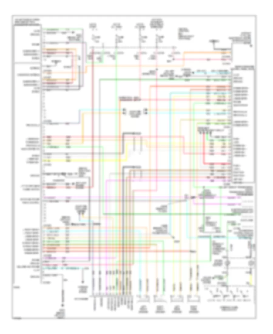 https://portal-diagnostov.com/license.html
Automotive Electricians Portal FZCO
Automotive Electricians Portal FZCO
https://portal-diagnostov.com/license.html
https://portal-diagnostov.com/license.html
Automotive Electricians Portal FZCO
Automotive Electricians Portal FZCOList of elements for Navigation Wiring Diagram, with Navigation for Ford Expedition 2003:
- (235)
- (at left side of cargo area, behind trim) subwoofer amplifier
- (at right "c" pillar) electronic hidden antenna module (eham)
- (behind left kick panel) g202
- (behind right kick panel) g200
- (expedition) (navigator)
- (in breakout to rear integrated control panel)
- (near breakout to c800)
- (near breakout to console 2 power point)
- (on left "b" pillar, behind trim) g300
- (on left side of transmission) digital transmission mission range sensor
- (or 1417)
- Air bag sliding contact
- Antenna
- Anti-lock brakes system
- Audio on
- Audio sys on
- Audio system on
- C175b
- C2188a
- C2188b
- C2188c
- C2188d
- C2188e
- C2188f
- C2188g
- C218b
- C270e
- C270h
- C270j
- C270m
- C349a
- C349b
- C4194a
- C4194b
- Cd changer
- Central junction box (behind right kick panel)
- Computer data lines system
- Cruise control system
- Delayed acc power
- Dvd player
- Electrochromatic inside mirror unit
- Expedition
- Fuse 10a
- Fuse 15a
- Fuse 25a
- Fuse 7.5a
- Fused ignition
- G202 (behind left kick panel)
- Ground
- Hot at all times
- Hot in start
- Hot with accessory delay relay energized
- Illum
- Interior lights system
- L front spkr +
- L front spkr -
- L ft wh spd sens
- L rear sig +
- L rear sig -
- L rear spkr +
- L rear spkr -
- L sig +
- L sig -
- Left front speaker
- Left rear speaker
- Left sig (+)
- Left sig (-)
- Left sig +
- Left sig -
- Media
- Mute
- Navigation antenna
- Navigator
- Nca
- Next
- Pnk
- Power
- Powertrain control module (on right side of firewall)
- Protocol a
- Protocol b
- R front spkr +
- R front spkr -
- R rear sig +
- R rear sig -
- R rear spkr +
- R rear spkr -
- R sig +
- R sig -
- Radio
- Radio control
- Rear integrated control panel (ricp)
- Rear seat entertainment circuit
- Red
- Right front speaker
- Right rear speaker
- Right sig (+)
- Right sig (-)
- Right sig +
- Right sig -
- S2006 (expedition)
- S205
- S290
- S342
- S381
- S388 s372
- S389
- S390
- Shield
- Steering wheel radio switch
- Subwoofer (+)
- Subwoofer (-)
- Switched power
- Tan
- Vol(+)
- Vol(-)
Radio Wiring Diagram, without Navigation for Ford Expedition 2003
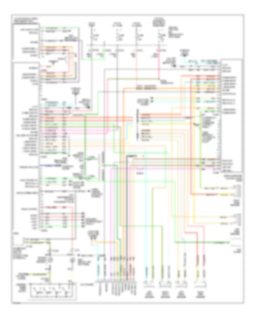 https://portal-diagnostov.com/license.html
Automotive Electricians Portal FZCO
Automotive Electricians Portal FZCO
https://portal-diagnostov.com/license.html
https://portal-diagnostov.com/license.html
Automotive Electricians Portal FZCO
Automotive Electricians Portal FZCOList of elements for Radio Wiring Diagram, without Navigation for Ford Expedition 2003:
- (at left side of cargo area, behind trim) subwoofer amplifier
- (behind right kick panel) g200
- (expedition)
- (in breakout to radio) s283
- (in breakout to rear integrated control panel)
- (navigator)
- (near breakout to c314)
- (near breakout to console 2 power point)
- (on left "b" pillar, behind trim) g300
- (or 1417)
- Air bag sliding contact
- Antenna
- Audio on
- Audio sys on
- Audio system on
- Base
- C175b
- C210
- C218b
- C270e
- C270h
- C270j
- C270m
- C290a
- C290b
- C290c
- C290d
- C349a
- C349b
- Cd changer
- Central junction box (behind right kick panel)
- Computer data lines system
- Cruise control system
- Delayed acc power
- Dvd player
- Except base
- Expedition
- Fuse 10a
- Fuse 15a
- Fuse 25a
- Fuse 7.5a
- Fused ignition
- G202 (behind left kick panel)
- Ground
- High audio mute
- Hot at all times
- Hot in start
- Hot with accessory delay relay energized
- Illum
- Interior lights system
- L front spkr +
- L front spkr -
- L rear spkr +
- L rear spkr -
- L sig +
- L sig -
- Left front speaker
- Left rear speaker
- Left sig (+)
- Left sig (-)
- Left sig +
- Left sig -
- Media
- Mute
- Navigation system
- Navigator
- Nca
- Next
- Parking aid mute
- Power
- Powertrain control module (on right side of firewall)
- Protocol a
- Protocol b
- R front spkr +
- R front spkr -
- R rear spkr +
- R rear spkr -
- R sig +
- R sig -
- Radio
- Radio control
- Rear integrated control panel (ricp)
- Rear seat entertainment circuit
- Red
- Right front speaker
- Right rear speaker
- Right sig (+)
- Right sig (-)
- Right sig +
- Right sig -
- S107 (near breakout to vapor management valve)
- S2006 (expedition)
- S202
- S205
- S290
- S303
- S372
- S388
- S389
- S390
- Shield
- Steering wheel radio switch
- Subwoofer (+)
- Subwoofer (-)
- Tan
- Vehicle speed sens
- Vol(+)
- Vol(-)
- Wiper/ washer, navigation systems
Rear Seat Entertainment Wiring Diagram, with Navigation for Ford Expedition 2003
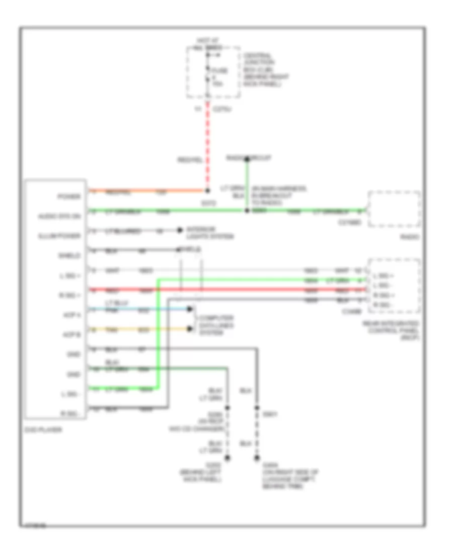 https://portal-diagnostov.com/license.html
Automotive Electricians Portal FZCO
Automotive Electricians Portal FZCO
https://portal-diagnostov.com/license.html
https://portal-diagnostov.com/license.html
Automotive Electricians Portal FZCO
Automotive Electricians Portal FZCOList of elements for Rear Seat Entertainment Wiring Diagram, with Navigation for Ford Expedition 2003:
- Acp a
- Acp b
- Audio sys on
- C2188d
- C270j
- C349b
- Central junction box (cjb) (behind right kick panel)
- Computer data lines system
- Dvd player
- Fuse 15a
- G202 (behind left kick panel)
- G404 (on right side of luggage compt, behind trim)
- Gnd
- Hot at all times
- Illum power
- Interior lights system
- L sig +
- L sig -
- Power
- R sig +
- R sig -
- Radio
- Radio circuit
- Rear integrated control panel (ricp)
- Red
- S290 (w/ ricp, w/o cd changer)
- S372
- S901
- Shield
- Tan
Rear Seat Entertainment Wiring Diagram, without Navigation for Ford Expedition 2003
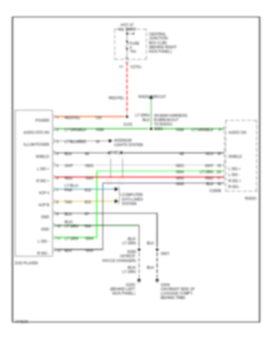 https://portal-diagnostov.com/license.html
Automotive Electricians Portal FZCO
Automotive Electricians Portal FZCO
https://portal-diagnostov.com/license.html
https://portal-diagnostov.com/license.html
Automotive Electricians Portal FZCO
Automotive Electricians Portal FZCOList of elements for Rear Seat Entertainment Wiring Diagram, without Navigation for Ford Expedition 2003:
- Acp a
- Acp b
- Audio on
- Audio sys on
- C270j
- C290b
- Central junction box (cjb) (behind right kick panel)
- Computer data lines system
- Dvd player
- Fuse 15a
- G202 (behind left kick panel)
- G404 (on right side of luggage compt, behind trim)
- Gnd
- Hot at all times
- Illum power
- Interior lights system
- L sig +
- L sig -
- Nca
- Power
- R sig +
- R sig -
- Radio
- Radio circuit
- Red
- S290 (w/ ricp, w/o cd changer)
- S372
- S901
- Shield
- Tan
SHIFT INTERLOCK
Shift Interlock Wiring Diagram for Ford Expedition 2003
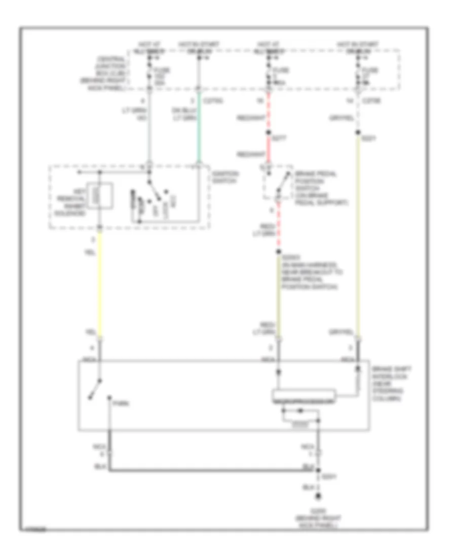 https://portal-diagnostov.com/license.html
Automotive Electricians Portal FZCO
Automotive Electricians Portal FZCO
https://portal-diagnostov.com/license.html
https://portal-diagnostov.com/license.html
Automotive Electricians Portal FZCO
Automotive Electricians Portal FZCOList of elements for Shift Interlock Wiring Diagram for Ford Expedition 2003:
- Acc
- Brake pedal position switch (on brake pedal support)
- Brake shift interlock (near steering column)
- C270e
- C270g
- Central junction box (cjb) (behind right kick panel)
- Fuse 30a
- Fuse 5a
- Fuse 7.5a
- G200 (behind right kick panel)
- Hot at all times
- Hot in start or run
- Ignition switch
- Key removal inhibit solenoid
- Lock
- Microprocessor
- Nca
- Off
- Park
- Run
- S2003 (in main harness, near breakout to brake pedal position switch)
- S201
- S221
- S277
- Start
STARTING/CHARGING
Charging Wiring Diagram for Ford Expedition 2003
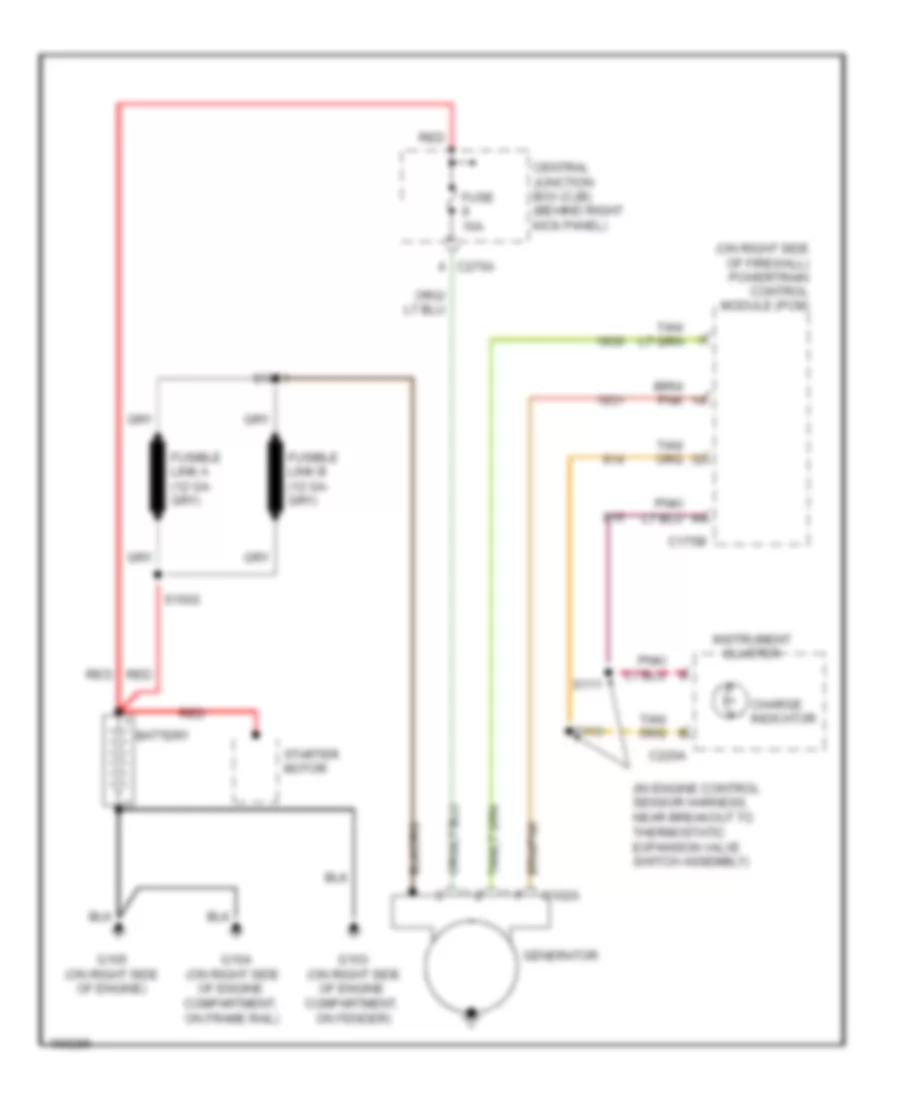 https://portal-diagnostov.com/license.html
Automotive Electricians Portal FZCO
Automotive Electricians Portal FZCO
https://portal-diagnostov.com/license.html
https://portal-diagnostov.com/license.html
Automotive Electricians Portal FZCO
Automotive Electricians Portal FZCOList of elements for Charging Wiring Diagram for Ford Expedition 2003:
- (in engine control sensor harness, near breakout to thermostatic expansion valve switch assembly)
- (on right side of firewall) powertrain control module (pcm)
- Battery
- C102a
- C175b
- C220a
- C270a
- Central junction box (cjb) (behind right kick panel)
- Charge indicator
- Fuse 10a
- G103 (on right side of engine compartment, on fender)
- G104 (on right side of engine compartment, on frame rail)
- G105 (on right side of engine)
- Generator
- Instrument cluster
- Red
- S1001
- S1002
- S110
- S111
- Starter motor
Starting Wiring Diagram for Ford Expedition 2003
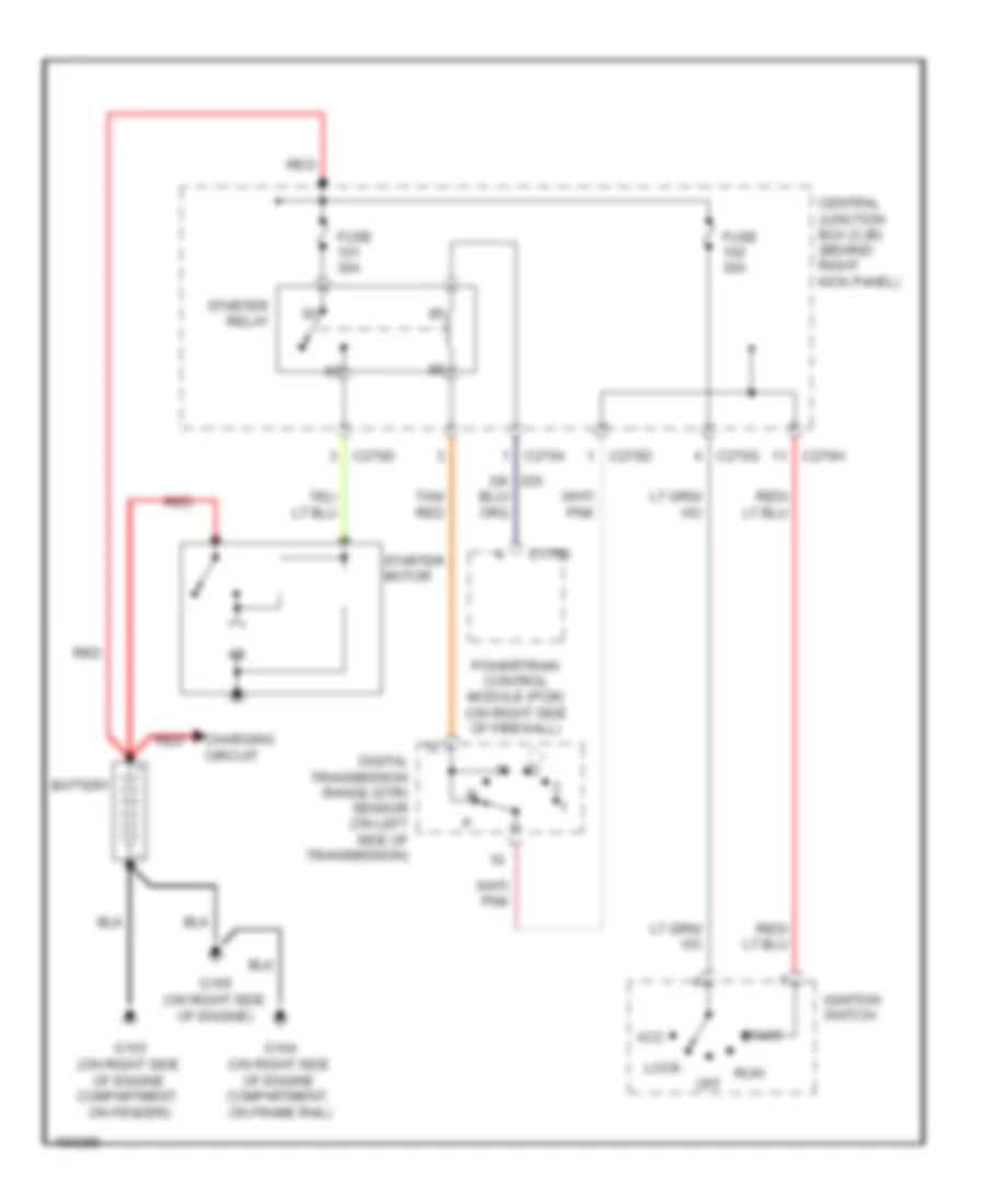 https://portal-diagnostov.com/license.html
Automotive Electricians Portal FZCO
Automotive Electricians Portal FZCO
https://portal-diagnostov.com/license.html
https://portal-diagnostov.com/license.html
Automotive Electricians Portal FZCO
Automotive Electricians Portal FZCOList of elements for Starting Wiring Diagram for Ford Expedition 2003:
- Acc
- Battery
- C175b
- C270a
- C270d
- C270g
- C270h
- Central junction box (cjb) (behind right kick panel)
- Charging circuit
- Digital transmission range (dtr) sensor (on left side of transmission)
- Fuse 30a
- G103 (on right side of engine compartment, on fender)
- G104 (on right side of engine compartment, on frame rail)
- G105 (on right side of engine)
- Ignition switch
- Lock
- Off
- Powertrain control module (pcm) (on right side of firewall)
- Red
- Run
- Start
- Starter motor
- Starter relay
- Tan/ red
SUPPLEMENTAL RESTRAINTS
Supplemental Restraints Wiring Diagram (1 of 2) for Ford Expedition 2003
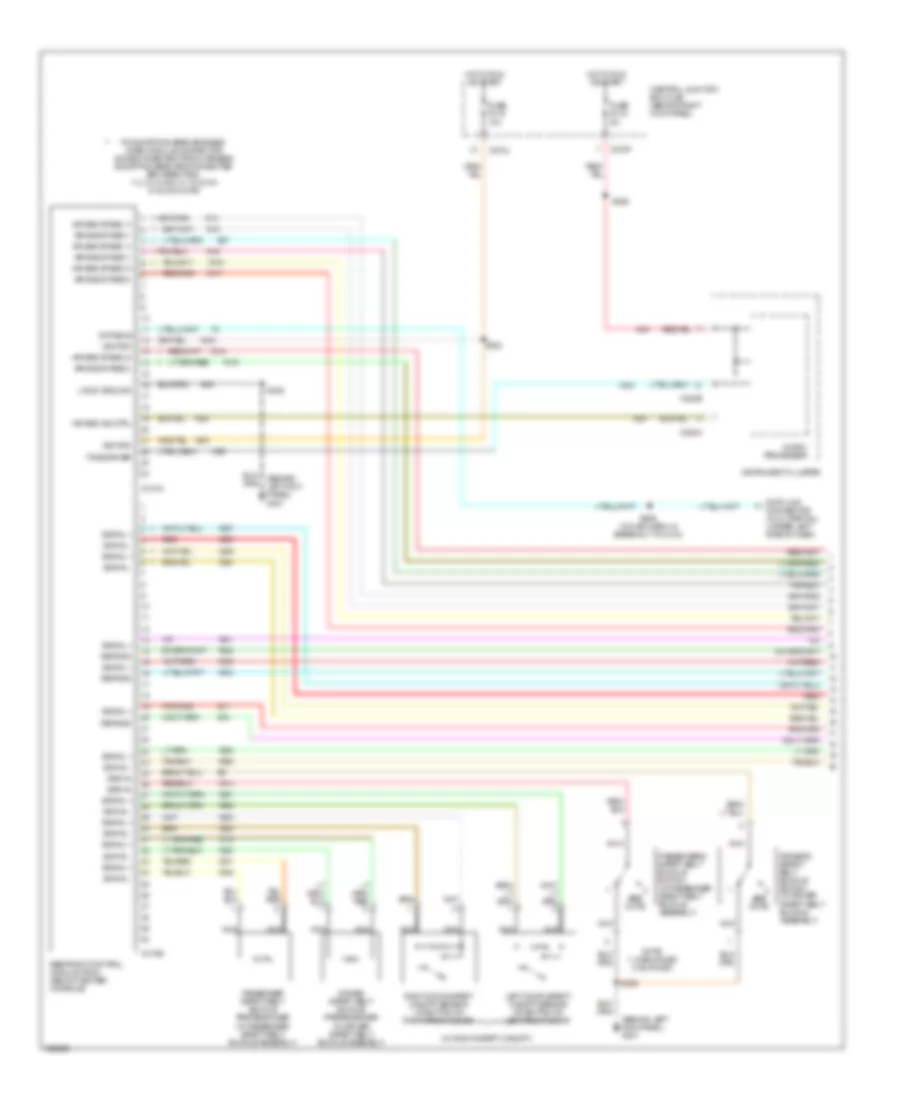 https://portal-diagnostov.com/license.html
Automotive Electricians Portal FZCO
Automotive Electricians Portal FZCO
https://portal-diagnostov.com/license.html
https://portal-diagnostov.com/license.html
Automotive Electricians Portal FZCO
Automotive Electricians Portal FZCOList of elements for Supplemental Restraints Wiring Diagram (1 of 2) for Ford Expedition 2003:
- (behind left kick panel) g301
- (in main harn, in breakout to c213)
- (w/ right safety canopy)
- Air bag ind ctrl
- Air bag stage 1+
- Air bag stage 1-
- Air bag stage 2+
- Air bag stage 2-
- C220a
- C220b
- C270f
- C270j
- C310a
- C310b
- Central junction box (cjb) (behind right kick panel)
- Data bus
- Data link connector (dlc) (partial) (under left side of dash)
- Driver safety belt buckle pretensioner (in driver safety belt buckle assembly)
- Driver's safety belt buckle switch (in driver safety belt buckle assembly)
- Fuse f2.15 5a
- Fuse f2.19 10a
- Hot in run or start
- Ignition
- Instrument cluster
- Left door safety canopy sensor (at bottom of left front door)
- Logic ground
- Micro- processor
- Nca
- Note: 1: unbuckled 2: buckled
- Passenger safety belt buckle pretensioner (in passenger safety belt buckle assembly)
- Passenger's safety belt buckle switch (in passenger safety belt buckle assembly)
- Pin shorting bars engaged when module connector is disconnected from harness (shorting bars are connected between pins: 1-2, 3-4, 5-6 & 13-14 c310a 3-4 & 5-6 c310b
- Red
- Ref/gnd
- Restraint control module (rcm) (below center console)
- Right door safety canopy sensor (at bottom of right front door)
- S229
- S282
- S308
- S320
- See note
- Signal
- Signal +
- Signal -
- Tone driver
Supplemental Restraints Wiring Diagram (2 of 2) for Ford Expedition 2003
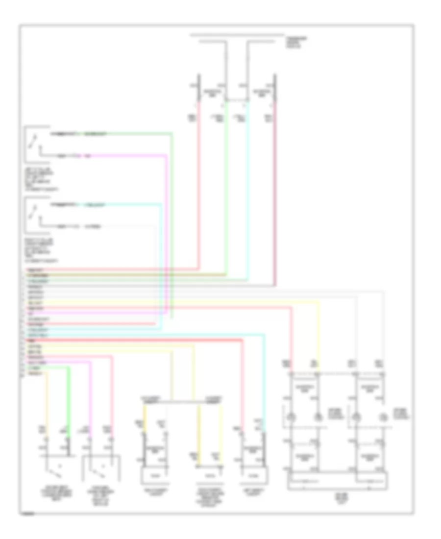 https://portal-diagnostov.com/license.html
Automotive Electricians Portal FZCO
Automotive Electricians Portal FZCO
https://portal-diagnostov.com/license.html
https://portal-diagnostov.com/license.html
Automotive Electricians Portal FZCO
Automotive Electricians Portal FZCOList of elements for Supplemental Restraints Wiring Diagram (2 of 2) for Ford Expedition 2003:
- (w/ safety canopy)
- Air bag sliding contact
- Driver air bag unit
- Driver seat position sensor (under driver's seat)
- Forward crash sensor (on left front of vehicle)
- Left "c" pillar canopy sensor (on left "c" pillar, behind trim) (w/ safety canopy)
- Left safety canopy
- Nca
- Passenger air bag module
- Red
- Right "c" pillar canopy sensor (on right "c" pillar, behind trim)
- Right safety canopy
- Right safety canopy delete resistor (on right side of roof)
- Shorting bar
- W/ safety canopy
- W/o safety canopy
TRANSMISSION
4WD Wiring Diagram for Ford Expedition 2003
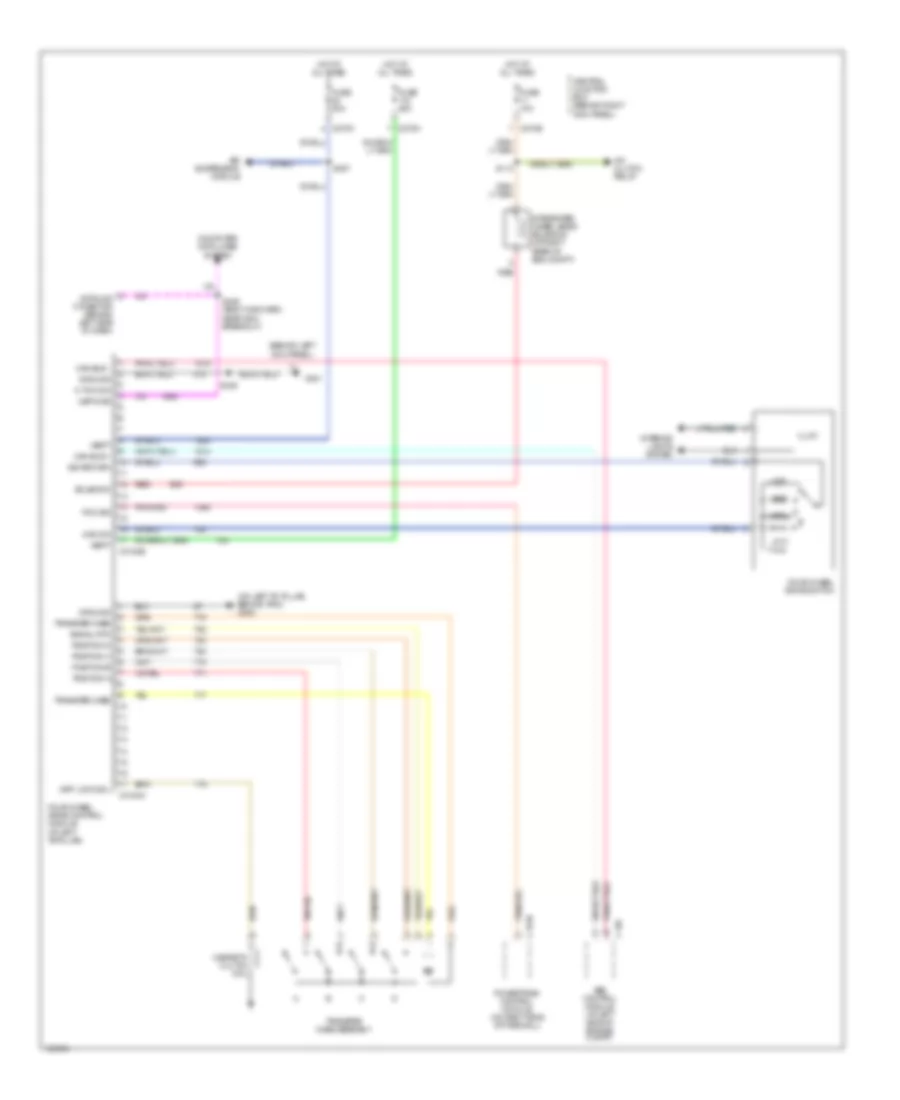 https://portal-diagnostov.com/license.html
Automotive Electricians Portal FZCO
Automotive Electricians Portal FZCO
https://portal-diagnostov.com/license.html
https://portal-diagnostov.com/license.html
Automotive Electricians Portal FZCO
Automotive Electricians Portal FZCOList of elements for 4WD Wiring Diagram for Ford Expedition 2003:
- (behind left kick panel)
- (on left "b" pillar, behind trim) g300
- 4wd sw
- A/c clutch relay
- Abs control module (at left side of engine compt)
- Air suspension module
- Awd
- C135
- C175b
- C270b
- C270k
- C270m
- C3184a
- C3184b
- Can bus +
- Can bus -
- Central junction box (behind right kick panel)
- Computer data lines system
- Datalink conector (behind left side of dash)
- Diff lock sol
- Four wheel drive control module (at left "b"pillar)
- Four-wheel drive switch
- Fuse 10a
- Fuse 30a
- G301
- Ground
- High
- Hot at all times
- Illum
- Integrated wheel ends solenoid (at right rear of eng compt)
- Interior lights system
- Low
- Magnetic clutch coil
- N tow sw
- Off
- Pcm sig
- Position a
- Position b
- Position c
- Position d
- Powertrain control module (on right side of firewall)
- Red
- S113
- S346
- S349 (body main harn, near g301 breakout)
- S357
- Sig return
- Signal rtn
- Solenoid
- Transfer case
- Transfer case assembly
- Ubp diag
- Vbatt
A/T Wiring Diagram (1 of 2) for Ford Expedition 2003
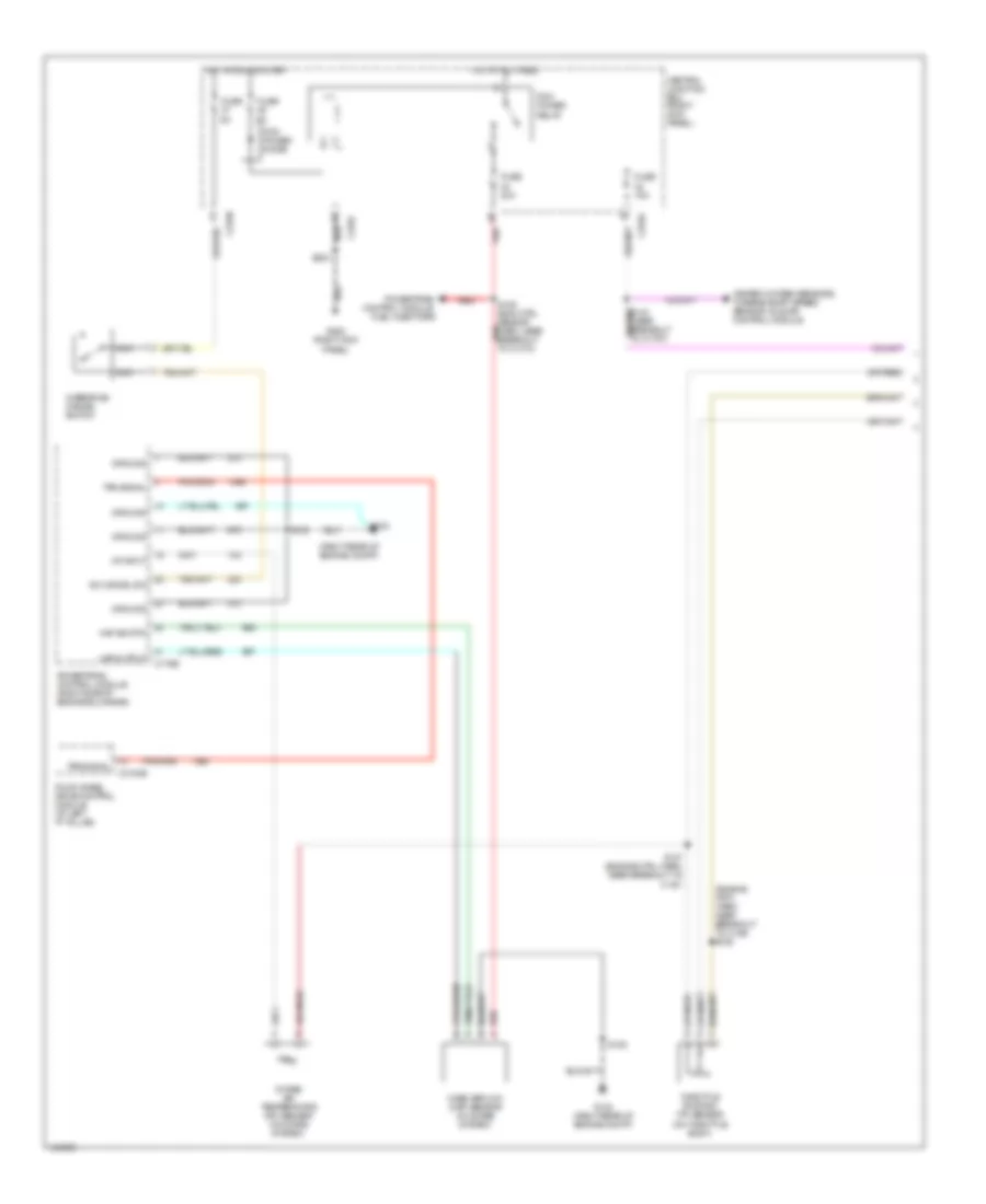 https://portal-diagnostov.com/license.html
Automotive Electricians Portal FZCO
Automotive Electricians Portal FZCO
https://portal-diagnostov.com/license.html
https://portal-diagnostov.com/license.html
Automotive Electricians Portal FZCO
Automotive Electricians Portal FZCOList of elements for A/T Wiring Diagram (1 of 2) for Ford Expedition 2003:
- (engine crtl harn, near breakout to c129) s125
- (right rear of engine compt)
- C175b
- C270a
- C270b
- C270f
- C3184b
- Central junction box (right kick panel)
- Four wheel drive control module (at left "p" pillar)
- Fuse
- Fuse 15a
- Fuse 20a
- G102
- G102 (right rear of engine compt)
- G200 (right kick panel)
- Ground
- Heated oxygen sensors, turbine shaft speed sensor, idle air control module
- Hot at all times
- Hot in run or start
- Iat input
- Intake air temperature (iat) sensor (in intake system)
- Maf output
- Maf sig rtn
- Mass airflow (maf) sensor (in intake system)
- Nca
- Od cancel sw
- Overdrive cancel switch
- Pcm power diode
- Pcm power relay
- Powertrain control module (right side of engine bulkhead)
- Powertrain control module, fuel injectors
- Red
- S108
- S109 (eng ctrl sensor red harn, near breakout to c1373)
- S127 (engine ctrl harn, near breakout to c187)
- S203
- Throttle position (tp) sensor (on throttle body)
- Tps signal
A/T Wiring Diagram (2 of 2) for Ford Expedition 2003
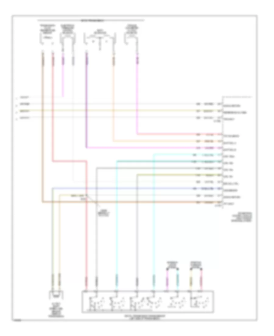 https://portal-diagnostov.com/license.html
Automotive Electricians Portal FZCO
Automotive Electricians Portal FZCO
https://portal-diagnostov.com/license.html
https://portal-diagnostov.com/license.html
Automotive Electricians Portal FZCO
Automotive Electricians Portal FZCOList of elements for A/T Wiring Diagram (2 of 2) for Ford Expedition 2003:
- (near breakout to c175t)
- 4r70w transmission
- C175e
- C175t
- Digital transmission range sensor (left side of transmission)
- Dtr, tr1
- Dtr, tr2
- Dtr, tr3a
- Dtr, tr4
- Electronic pressure control solenoid
- Epc sol ctrl
- Exterior lights system
- Oss sensor
- Output shaft speed (oss) sensor (rear of transmission)
- Powertrain control module (right side of engine bulkhead)
- R n
- Reference voltage
- S138
- Shift sol a
- Shift sol b
- Shift solenoids
- Signal return
- Starting/ charging system
- Tan/red
- Tcc solenoid
- Tft input
- Torque converter clutch solenoid
- Tps input
- Transmission fluid temperature sensor
TRUNK, TAILGATE, FUEL DOOR
Trunk, Tailgate, Fuel Door Wiring Diagram for Ford Expedition 2003
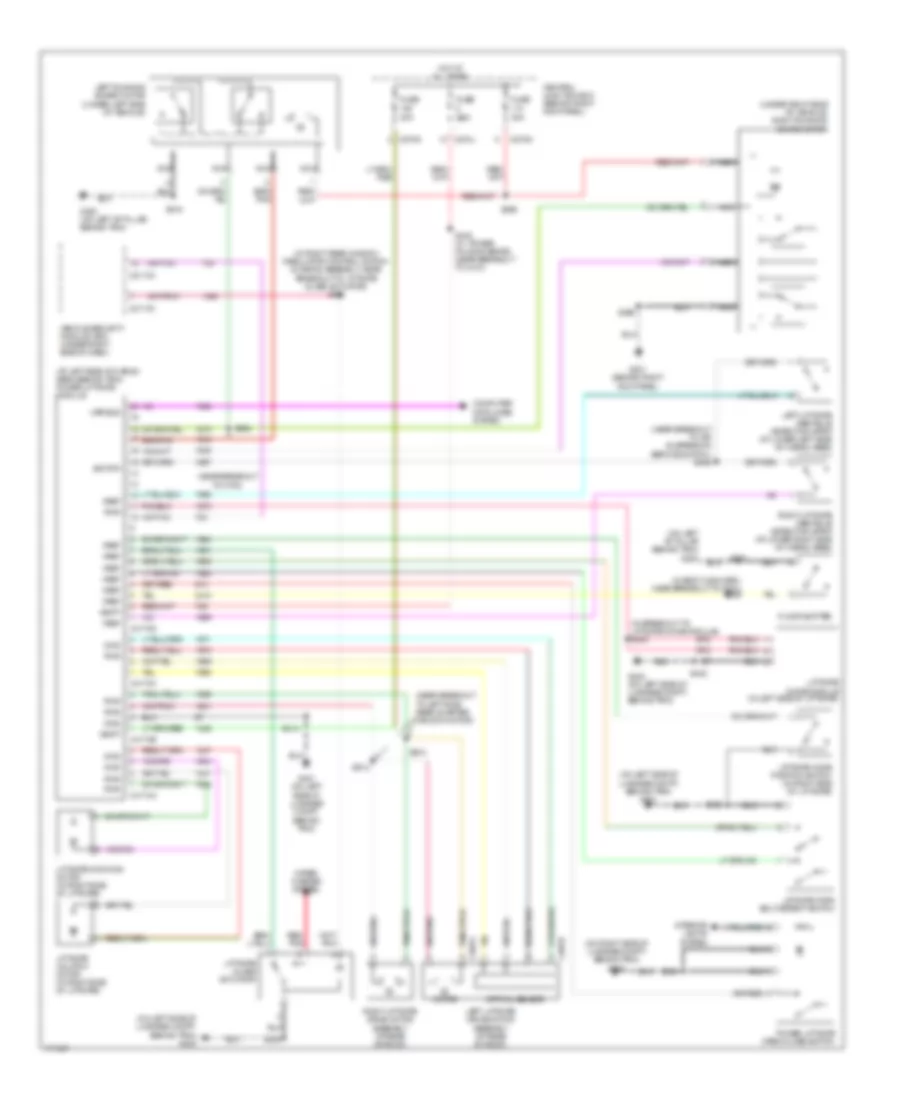 https://portal-diagnostov.com/license.html
Automotive Electricians Portal FZCO
Automotive Electricians Portal FZCO
https://portal-diagnostov.com/license.html
https://portal-diagnostov.com/license.html
Automotive Electricians Portal FZCO
Automotive Electricians Portal FZCOList of elements for Trunk, Tailgate, Fuel Door Wiring Diagram for Ford Expedition 2003:
- (at left side of cargo area, behind trim) power liftgate module
- (in body main harn, near breakout to g301) s369
- (in breakout to liftgate chime module) s400
- (in right rear window regulator control switch & wiring assembly, near breakout to liftgate glass actuator) s465
- (near breakout to air suspension service switch) s458
- (near breakout to c700)
- (near breakout to left side rear quarter window motor)
- (on left "b" pillar behind trim) g300
- (on left side of luggage compt, behind trim) g401
- (on left side of luggage compt, behind trim) g402
- (on right side of luggage compt, behind trim) g404
- (under right side of vehicle) right running board motor
- 30a
- 7.5a
- C2113a
- C2113c
- C270g
- C270j
- C270n
- C4174a
- C4174b
- C4174c
- C4174d
- C997a
- C997b
- Central junction box (behind right kick panel)
- Computer data lines system
- Floor shifter
- Fuse
- G201 (behind right kick panel)
- G300 (on left "b" pillar, behind trim)
- G401 (on left side of luggage compt, behind trim)
- G402 (on left side of luggage compt, behind trim)
- Gnd
- Hot at all times
- Interior lights system
- Left liftgate drive motor assembly (at rear of roof)
- Left liftgate obstacle detection strip (at lower left side of cargo area)
- Left running board motor (under left side of vehicle)
- Liftgate chime module (in left side of liftgate)
- Liftgate cinching motor (in right side of liftgate)
- Liftgate fork bolt/detent switch
- Liftgate glass actuator
- Liftgate home position switch (in right side of liftgate)
- Liftgate unlatch motor (in right side of liftgate)
- Motor
- Nca
- Optical sensor
- Power liftgate open/close switch
- Pwr
- Red/ pnk
- Right liftgate drive motor assembly (at rear of roof)
- Right liftgate obstacle detection strip (at lower right side of cargo area)
- S205
- S316
- S356
- S394
- S395
- S402
- S414
- S448 (w/ power folding seats) (near breakout to c410)
- S463
- S904
- S910
- S914
- Sig rtn
- Upb bus
- Vbatt
- Vehicle security module (vsm) (under right side of dash)
- Vref
- Wiper/ washer system
WARNING SYSTEMS
Tire Pressure Monitoring Wiring Diagram for Ford Expedition 2003
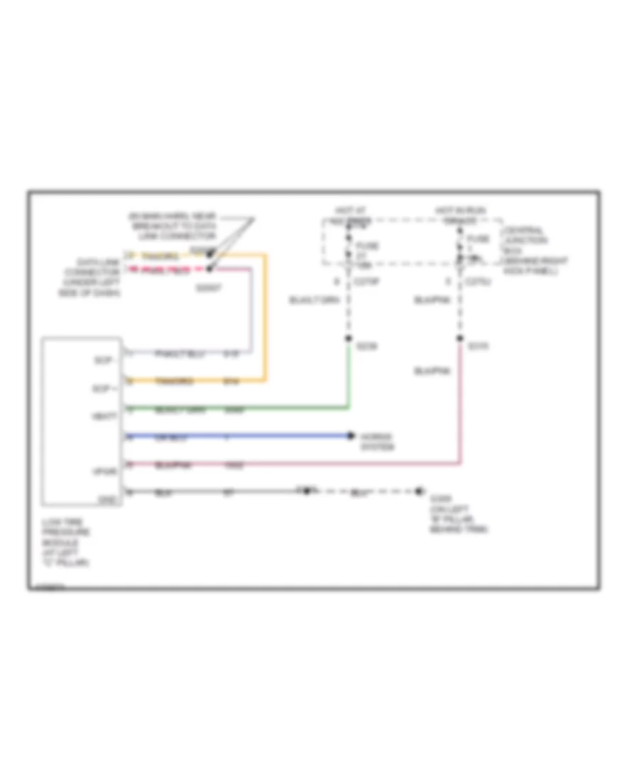 https://portal-diagnostov.com/license.html
Automotive Electricians Portal FZCO
Automotive Electricians Portal FZCO
https://portal-diagnostov.com/license.html
https://portal-diagnostov.com/license.html
Automotive Electricians Portal FZCO
Automotive Electricians Portal FZCOList of elements for Tire Pressure Monitoring Wiring Diagram for Ford Expedition 2003:
- (in main harn, near breakout to data link connector
- C270f
- C270j
- Central junction box (behind right kick panel)
- Data link connector (under left side of dash)
- Fuse 10a
- Fuse 15a
- G300 (on left "b" pillar, behind trim)
- Gnd
- Horns system
- Hot at all times
- Hot in run or acc
- Low tire pressure module (at left "c" pillar)
- S2007
- S2008
- S238
- S315
- S316
- Scp +
- Scp -
- Vbatt
- Vpwr
Warning Systems Wiring Diagram for Ford Expedition 2003
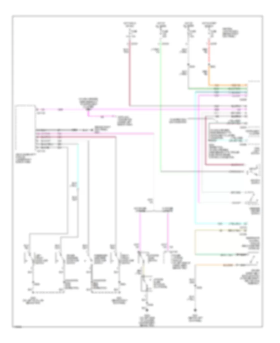 https://portal-diagnostov.com/license.html
Automotive Electricians Portal FZCO
Automotive Electricians Portal FZCO
https://portal-diagnostov.com/license.html
https://portal-diagnostov.com/license.html
Automotive Electricians Portal FZCO
Automotive Electricians Portal FZCOList of elements for Warning Systems Wiring Diagram for Ford Expedition 2003:
- (behind right kick panel) g201
- (in main harness, near breakout to instrument cluster) (navigator) s2024
- (in main harness, near breakout to instrument cluster) s264
- (navigator)
- 19 (expedition) 505 (navigator)
- C205b
- C2113a
- C2113c
- C220a
- C220b
- C270f
- C270g
- C310a
- C310b
- C4174d
- Central junction box (behind right kick panel)
- Data link connector (under left side of dash)
- Driver safety belt buckle switch (in driver safety belt buckle assembly)
- Driver side rear door ajar switch
- Fuse 10a
- Fuse 15a
- Fuse 30a
- Fuse 5a
- G201 (behind right kick panel)
- G300 (on left "b" pillar, behind trim)
- G301 (behind left kick panel)
- G402 (on left side of luggage compartment, behind trim)
- Hot at all times
- Hot in run or acc
- Hot in start or run
- Ignition switch
- Instrument cluster
- Key in
- Left front door ajar switch
- Liftgate ajar switch
- Liftgate glass actuator (in liftgate)
- Main light switch
- Message center switch
- Nca
- Passenger side rear door ajar switch
- Power liftgate module (at left side of cargo area, behind trim)
- Restraints control module (below center console)
- Right front door ajar switch
- S238
- S242 (expedition) (in main harness, near breakout to trailer electronic brake control connector)
- S282
- S308
- S356
- S402
- S506
- S600
- Vehicle security module (under right side of dash)
- W/ power liftgate
- W/o power liftgate
WIPER/WASHER
Front Washer/Wiper Wiring Diagram for Ford Expedition 2003
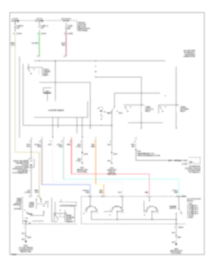 https://portal-diagnostov.com/license.html
Automotive Electricians Portal FZCO
Automotive Electricians Portal FZCO
https://portal-diagnostov.com/license.html
https://portal-diagnostov.com/license.html
Automotive Electricians Portal FZCO
Automotive Electricians Portal FZCOList of elements for Front Washer/Wiper Wiring Diagram for Ford Expedition 2003:
- (near breakout to vapor management valve)
- (on left side of firewall) windshield wiper motor
- (on left side of luggage compt, behind trim)
- 1. off 2. interval 1 3. interval 2 4. interval 3 5. interval 4 6. interval 5 7. slow 8. fast
- C175b
- C202a
- C270b
- C270d
- C270m
- Central junction box (cjb) (behind right kick panel)
- Front and rear washer pump motor (on right side of engine compt, on washer fluid reservoir)
- Front washer pump relay
- Fuse 1 10a
- Fuse 113 30a
- Fuse 38 25a
- G100 (near left side of radiator)
- G200 (behind right kick panel)
- G301 (behind left kick panel)
- G402
- Hall sensor
- Hot at all times
- Hot in run or acc
- Liftgate)
- Microprocessor
- Multi-function switch
- Park
- Powertrain control module (on right side of firewall)
- Rear washer pump relay
- Rear wiper motor assembly (in
- Rear wiper relay
- Red
- Rest
- Run
- S104
- S106
- S107
- S201
- S402
- Vss +
- Washer switch
- Wiper high/low relay
- Wiper run/park relay
Rear Washer/Wiper Wiring Diagram for Ford Expedition 2003
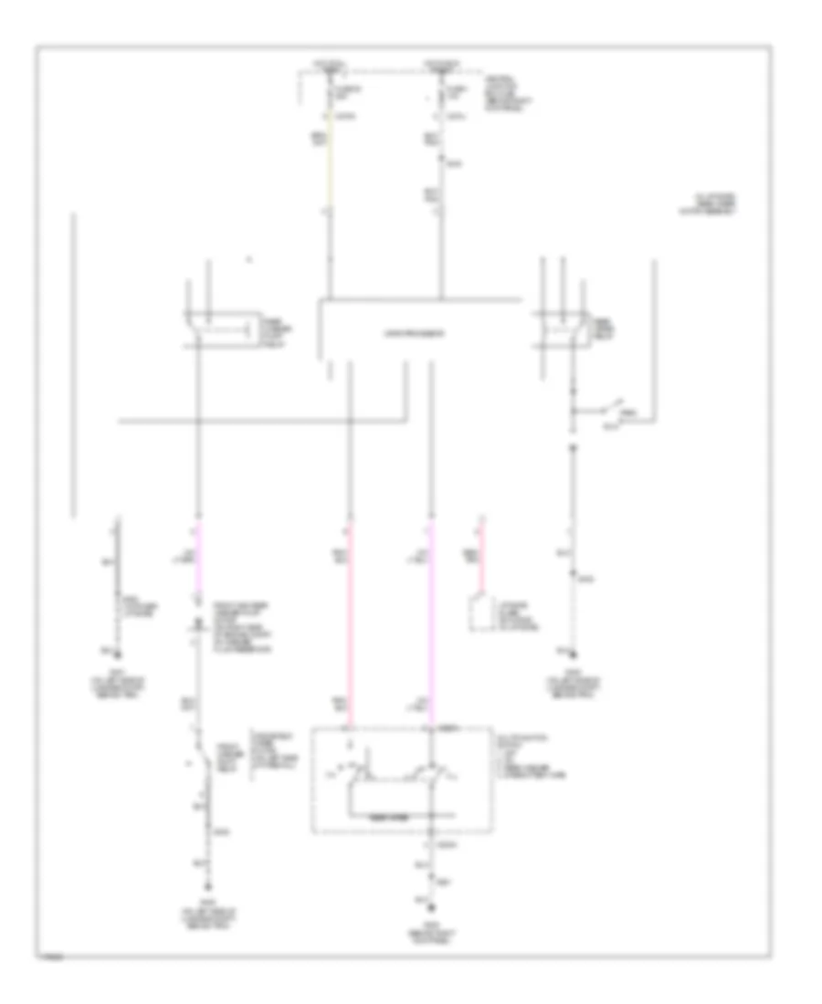 https://portal-diagnostov.com/license.html
Automotive Electricians Portal FZCO
Automotive Electricians Portal FZCO
https://portal-diagnostov.com/license.html
https://portal-diagnostov.com/license.html
Automotive Electricians Portal FZCO
Automotive Electricians Portal FZCOList of elements for Rear Washer/Wiper Wiring Diagram for Ford Expedition 2003:
- (in liftgate) rear wiper motor assembly
- (on left side of luggage compt, behind trim)
- 1. off 2. on 3. rear washer 4. intermittent wipe
- C202a
- C270j
- C270m
- Central junction box (cjb) (behind right kick panel)
- Front and rear washer pump motor (on right side of engine compt, on washer fluid reservoir)
- Front washer pump relay
- Fuse 1 10a
- Fuse 38 25a
- G200 (behind right kick panel)
- G401 (on left side of luggage compt, behind trim)
- G402
- G402 (on left side of luggage compt, behind trim)
- Hot at all times
- Hot in run or acc
- Liftgate glass actuator (in liftgate)
- Microprocessor
- Multifunction switch
- Park
- Rear washer pump relay
- Rear wiper
- Rear wiper relay
- Red/ pnk
- Run
- S201
- S315
- S402
- S463 (w/ power liftgate)
- Windshield wiper motor (on left side of firewall)

 Čeština
 Dansk
Dansk Deutsch
 Ελληνικά
 English
 English
 Español
 Suomi
Suomi Français
 Français
 עברית
עברית Hrvatski
 Magyar
 Italiano
 日本語
日本語 한국어
한국어 Nederlands
 Polski
 Português
 Português
 Română
 Русский
 Slovenčina
 Slovenščina
 Svenska
 Türkçe
