AIR CONDITIONING
A/C Wiring Diagram, Auto A/C (1 of 2) for Ford Explorer 1998
 https://portal-diagnostov.com/license.html
Automotive Electricians Portal FZCO
Automotive Electricians Portal FZCO
https://portal-diagnostov.com/license.html
https://portal-diagnostov.com/license.html
Automotive Electricians Portal FZCO
Automotive Electricians Portal FZCO
List of elements for A/C Wiring Diagram, Auto A/C (1 of 2) for Ford Explorer 1998:
- (near breakout for instrument cluster) s209
- (near breakout to i/p fuse panel) s217
- (near breakout to radio) s200
- (near breakout to rear blower motor relay) s210
- (near breakout to rear window defrost relay) s263
- (not used)
- (rear of left front fender) g104
- (rear of right front fender) g105
- 87a
- A/c demand
- Amb temp sens input
- Ambient air temperature sensor (left front of engine compartment)
- Audio/climate control switch assembly
- Battery
- Blend door 5v+
- Blend door act gnd
- Blend door actuator
- Blend door actuator (behind right side of dash, top of a/c plenum)
- Blend door ref
- Blower motor (right side of engine compartment)
- Blower motor relay
- Blower motor speed controller (near blower motor)
- Blower mtr fback
- Blower mtr rly gnd
- Blr mtr rly out
- C297
- C298
- Clockspring assembly
- Cruise control
- Data (+)
- Data (-)
- Eatc to clockspring
- Electronic automatic temperature control (eatc) module (behind center of dash)
- English/metric in
- Fan
- Fuse 7.5a
- Fuse 2 40a
- Ground
- Hot at all times
- Hot in run
- I/p fuse panel
- Illumination
- In car temp sens
- In-car temperature sensor (behind top center of dash)
- Input ground
- Inst illum
- Interior lights system
- Lamp illum
- Message center
- Nca
- Ohms
- Power
- Power distribution box (left side of engine compartment, at fender apron)
- Rear blr rly gnd
- Red
- Sound systems
- Speed control servo/ amplifier assembly (in right rear engine compartment)
- Speed ctrl out
- Speed ctrl sw gnd
- Sun load sensor (top right side of dash, above glove box)
- Sunload sens input
- Temp
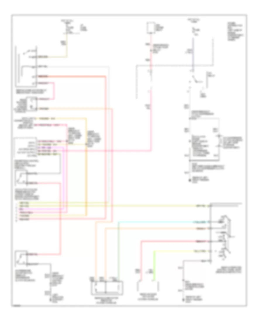
A/C Wiring Diagram, Auto A/C (2 of 2) for Ford Explorer 1998
 https://portal-diagnostov.com/license.html
Automotive Electricians Portal FZCO
Automotive Electricians Portal FZCO
https://portal-diagnostov.com/license.html
https://portal-diagnostov.com/license.html
Automotive Electricians Portal FZCO
Automotive Electricians Portal FZCOList of elements for A/C Wiring Diagram, Auto A/C (2 of 2) for Ford Explorer 1998:
- (left radiator support) g108
- (near branch to fuel pump relay) s123
- (near breakout to 4wabs control module) s137
- (near breakout to a/c compressor clutch) s133
- (near breakout to ground g201, under right side of i/p) s205
- (near breakout to ground g201, under right side of i/p) s206
- (not used)
- (rear of left front fender) g104
- 87a
- A/c clutch cycling pressure switch (in right side of engine compartment, on a/c accumulator)
- A/c clutch diode (left side of engine compartment, near a/c compressor clutch, taped in harness)
- A/c compressor clutch solenoid (on left side of engine compartment)
- A/c cps
- A/c hpcs input
- A/c pressure cutoff switch (near a/c compressor clutch solenoid)
- A/c relay
- A/c wot output
- Connector (dlc) (partial) (behind left side of dash)
- Data +
- Data -
- Data link
- Fuse 7.5a
- Fuse 10a
- Hot at all times
- I/p fuse panel
- Low
- Low med
- Med
- Off
- Pcm power relay
- Power distribution box (left side of engine compartment, at fender apron)
- Powertrain control module (pcm) (mounted through firewall)
- Rear air door actuator (in dash console)
- Rear blower motor (in rear of center console)
- Rear blower motor relay (behind right side dash)
- Rear blower motor resistor (in dash console)
- Rear integrated control panel (ricp) (rear blower switch)
- Red
- S100 (between diode & breakout for a/c compressor clutch solenoid)
- S231 (near breakout to rear blower motor)
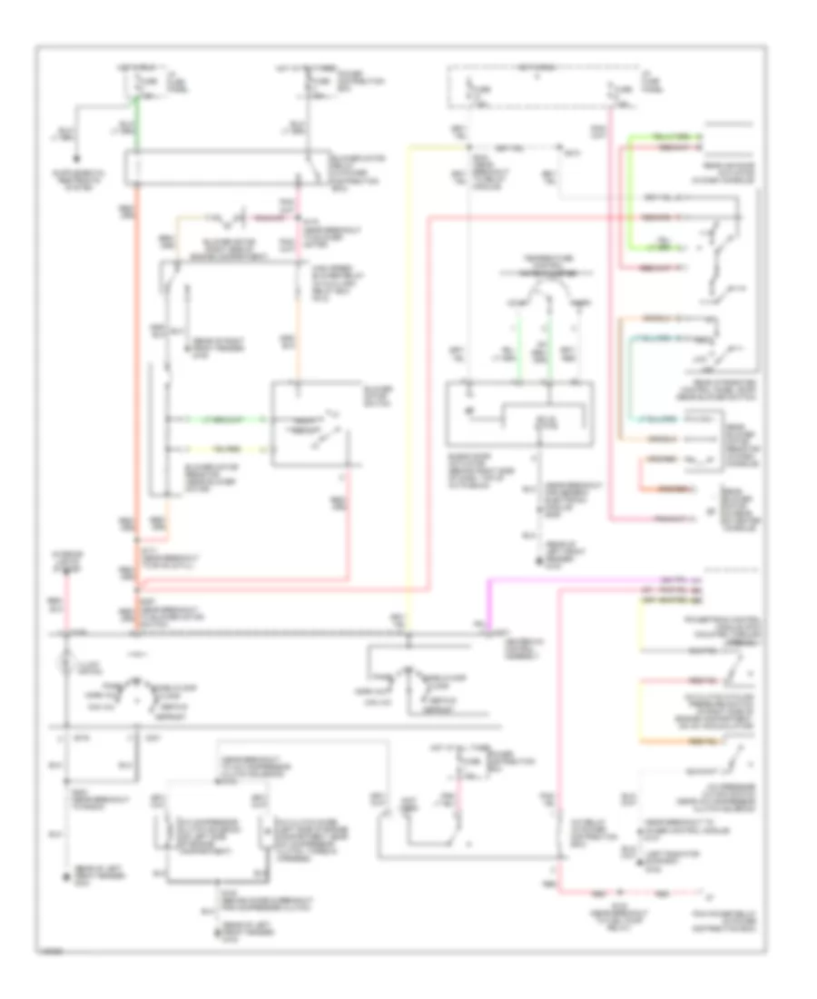
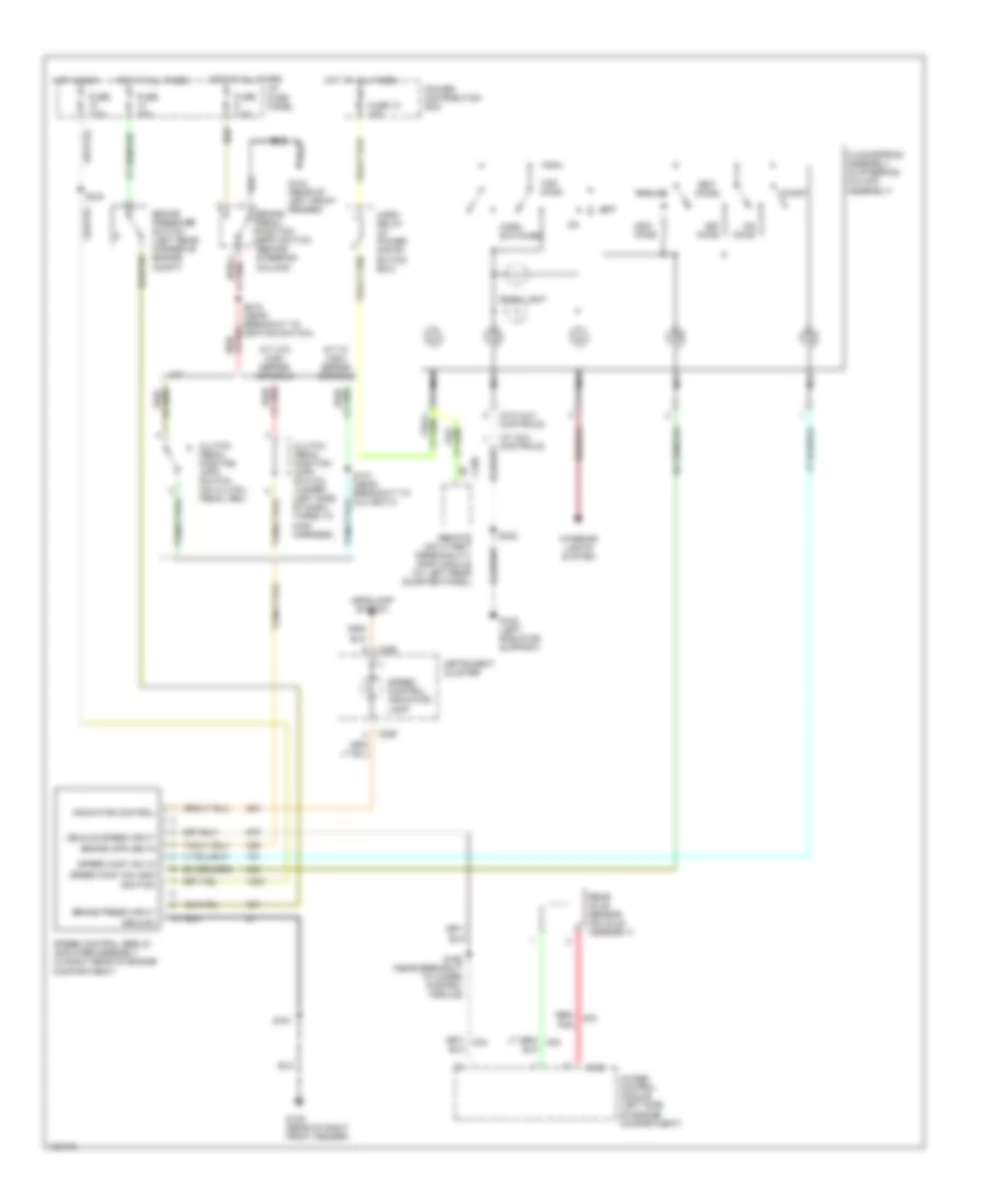
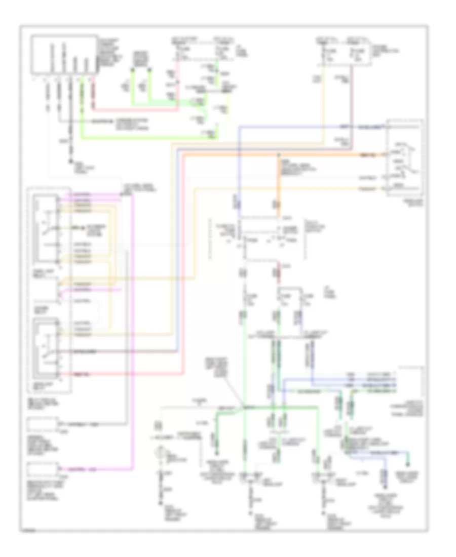
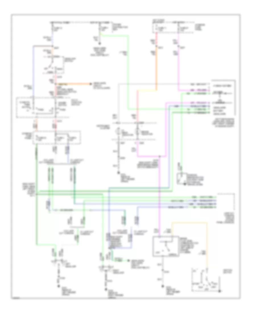
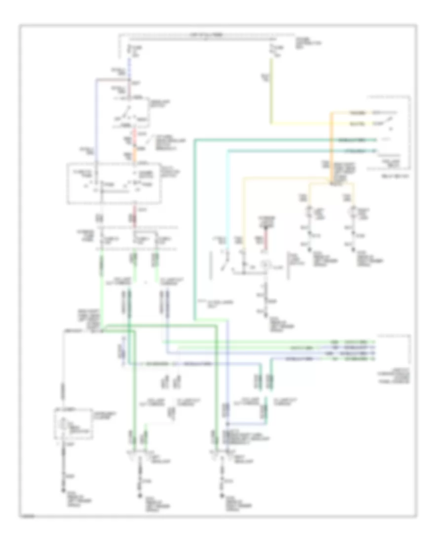
A/C Wiring Diagram, Manual A/C for Ford Explorer 1998
 https://portal-diagnostov.com/license.html
Automotive Electricians Portal FZCO
Automotive Electricians Portal FZCO
https://portal-diagnostov.com/license.html
https://portal-diagnostov.com/license.html
Automotive Electricians Portal FZCO
Automotive Electricians Portal FZCOList of elements for A/C Wiring Diagram, Manual A/C for Ford Explorer 1998:
- (left radiator support) g108
- (near breakout for generic electronic module) s229
- (near breakout to 4wabs control module) s137
- (near breakout to a/c compressor clutch solenoid) s133
- (not used)
- (rear of left front fender) g104
- (rear of right front fender) g105
- A/c clutch cycling pressure switch (in right side of engine compartment, on a/c accumulator)
- A/c clutch diode (left side of engine compartment, near a/c compressor clutch, taped in harness)
- A/c compressor clutch solenoid (on left side of engine compartment)
- A/c pressure cutoff switch (near a/c compressor clutch solenoid)
- A/c relay (in power distribution box)
- Blend door actuator (behind right side of dash, top of a/c plenum)
- Blower motor (right side of engine compartment)
- Blower motor relay (in power distribution box)
- Blower motor resistor (near blower motor)
- Blower motor switch
- C231
- C276
- Cold
- Def/flr
- Defrost
- Floor
- Fuse 7.5a
- Fuse 10a
- Fuse 40a
- Fuse 7.5a
- Heater-a/c control assembly
- High speed blower relay (in auxiliary relay box no.2)
- Hot at all times
- Hot in run
- I/p fuse panel
- Illumi- nation
- Interior lights system
- Low
- Max a/c
- Med
- Med hi
- Med lo
- Norm a/c
- Off
- Off panel
- Panel
- Panel/floor
- Pcm power relay (in power distribution box)
- Power distribution box
- Powertrain control module (pcm) (mounted through firewall)
- Rear air door actuator (in dash console)
- Rear blower motor (in rear of center console)
- Rear blower motor resistor (in dash console)
- Rear integrated control panel (ricp) (rear blower switch)
- Red
- S100 (behind diode & breakout for compressor clutch)
- S123 (near breakout to fuel pump relay)
- S170 (near breakout to blower motor)
- S171 (near breakout to evac & fill)
- S200 (near breakout to radio)
- S210
- Solid state
- Temperature control potentiometer
- To blower motor switch)
- To relay module)
- Warm
ANTI-LOCK BRAKES
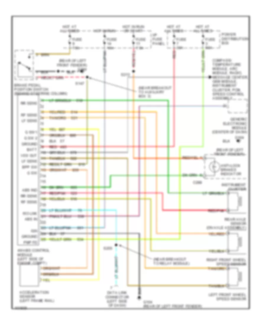
Anti-lock Brake Wiring Diagrams for Ford Explorer 1998
 https://portal-diagnostov.com/license.html
Automotive Electricians Portal FZCO
Automotive Electricians Portal FZCO
https://portal-diagnostov.com/license.html
https://portal-diagnostov.com/license.html
Automotive Electricians Portal FZCO
Automotive Electricians Portal FZCOList of elements for Anti-lock Brake Wiring Diagrams for Ford Explorer 1998:
- (near breakout to auxiliary box 3)
- (near breakout to relay module)
- (rear of left front fender)
- (rear of left front fender) g104
- 4wabs control module (left side of engine compt)
- Abs in
- Abs ind
- Acceleration sensor (left frame rail)
- Anti-lock brakes indicator
- Batt
- Bpp sw
- Brake pedal position switch (behind steering column)
- C288
- Compass/ temperature module, arc module, radio, message center, gem module, instrument cluster, pcm, speed control assembly
- Data link connector (left side of dash)
- Fuse 10a
- Fuse 30a
- Fuse 50a
- Fuse 7.5a
- G sw
- G sw 2
- G sw1
- G104
- G104 (rear of left front fender)
- Generic electronic module (center of dash)
- Ground
- Hot at all times
- Hot in run
- Hot in run or start
- I/p fuse panel
- Ign
- Instrument cluster
- Iso lnk
- Left front wheel speed sensor
- Lf sens
- Pmp fd
- Power distribution box
- Rear axle sensor (on axle assembly)
- Red
- Red/pnk
- Rf sens
- Right front wheel speed sensor
- Rr sens
- S147
- S213
- S255
- Vss out
ANTI-THEFT
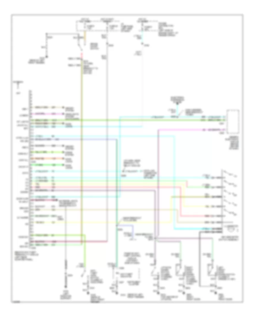
Forced Entry Wiring Diagram for Ford Explorer 1998
 https://portal-diagnostov.com/license.html
Automotive Electricians Portal FZCO
Automotive Electricians Portal FZCO
https://portal-diagnostov.com/license.html
https://portal-diagnostov.com/license.html
Automotive Electricians Portal FZCO
Automotive Electricians Portal FZCOList of elements for Forced Entry Wiring Diagram for Ford Explorer 1998:
- "r" input
- (i/p harn, near breakout to relay module)
- (main harness, near breakout to gem)
- (near breakout to cluster)
- (near breakout to gem) s275
- (not used)
- (rear of left front fender)
- 1/2
- 3/4
- 5/6
- 7/8
- 9/0
- Ant
- Antenna
- Anti- theft hood switch (closed w/ hood open)
- Anti-theft indicator
- Bat
- Boo sw
- Brake on/off switch
- C280
- C281
- C286
- C287
- C336
- C338
- Com
- Data
- Data link connector (left side of dash)
- Disarm
- Door ajar
- Door locks
- Electronic suspension system
- Exterior lights (tr sensor-a/t) (backup sw-m/t)
- Fuse 20 7.5a
- Fuse 9 20a
- Fuse 9 7.5a
- G104
- G104 (rear of left front fender)
- G105 (rear of right front fender)
- G108 (left radiator support)
- G412 (top center of liftgate)
- G500 (left front door)
- G600 (right front door)
- Generic electronic module (behind center of dash)
- Ground
- Headlights system (autolamps)
- Hood sw
- Horn rly
- Horns system
- Hot at all times
- Hot in accy or run
- I/p fuse panel (left side of dash)
- Ig tamper
- Ign
- Illumination
- Ind led
- Instrument cluster
- Int lights
- Keyless entry switch assembly
- Kypd illum
- Left front door disarm switch (closed if opened w/ key)
- Liftgate disarm switch (closed if opened w/key)
- Lo beam
- Lock all
- Mem 1
- Mem 2
- Memory system
- Nca
- Passive anti- theft control module (top right side of dash)
- Power distribution box (left side of engine compt, at fender apron)
- Red
- Remote anti-theft personality module (left rear quarter panel)
- Right front door disarm switch (closed if opened w/key)
- S160
- S161
- S215 (i/p harn, near breakout to ignition switch)
- S229
- S230
- S234
- S245
- S255
- S258
- S282
- S404
- S500
- S602
- Unlck all
- Unlck lf
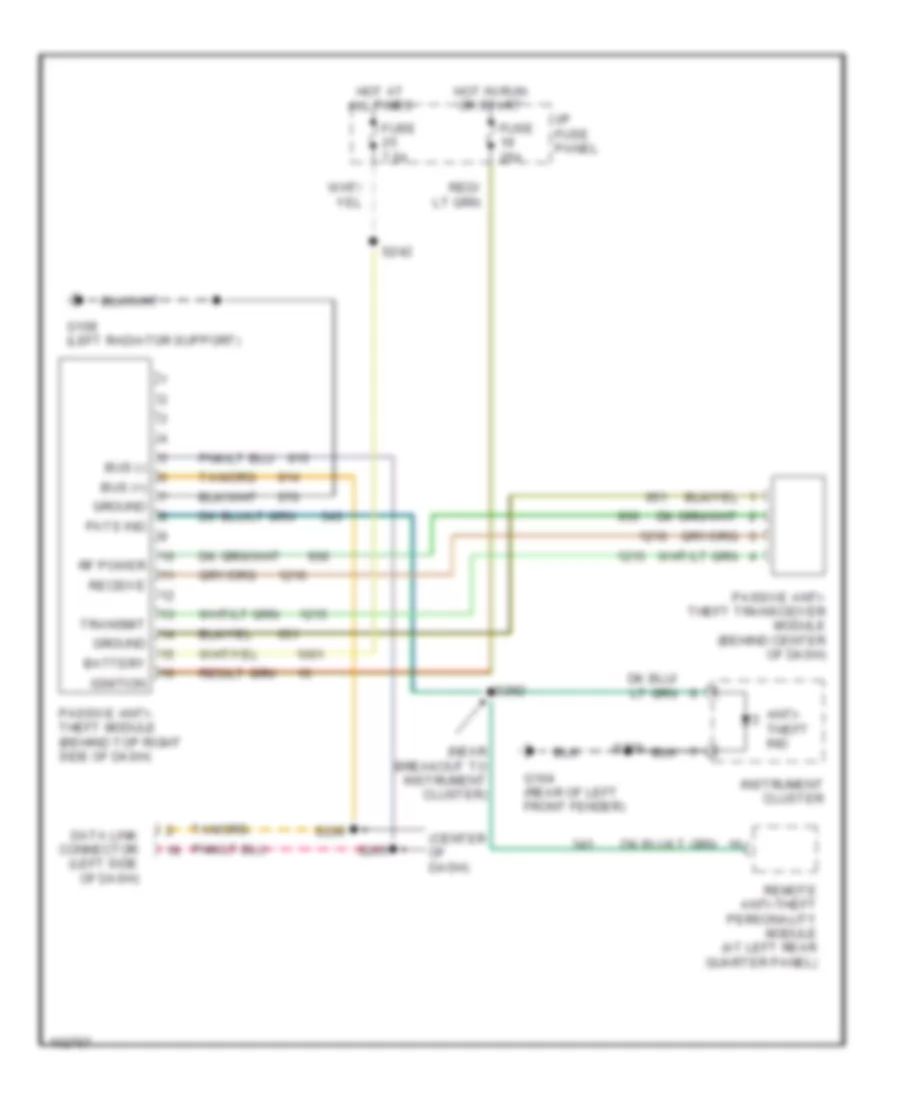
Passive Anti-theft Wiring Diagram for Ford Explorer 1998
 https://portal-diagnostov.com/license.html
Automotive Electricians Portal FZCO
Automotive Electricians Portal FZCO
https://portal-diagnostov.com/license.html
https://portal-diagnostov.com/license.html
Automotive Electricians Portal FZCO
Automotive Electricians Portal FZCOList of elements for Passive Anti-theft Wiring Diagram for Ford Explorer 1998:
- (center of dash)
- (near breakout to instrument cluster)
- Anti- theft ind
- Battery
- Bus (+)
- Bus (-)
- Data link connector (left side of dash)
- Fuse 25a
- Fuse 7.5a
- G104 (rear of left front fender)
- G108 (left radiator support)
- Ground
- Hot at all times
- Hot in run or start
- I/p fuse panel
- Ignition
- Instrument cluster
- Passive anti- theft module (behind top right side of dash)
- Passive anti- theft transceiver module (behind center of dash)
- Pats ind
- Receive
- Remote anti-theft personality module (at left rear quarter panel)
- Rf power
- S205
- S206
- S229
- S242
- S282
- Transmit
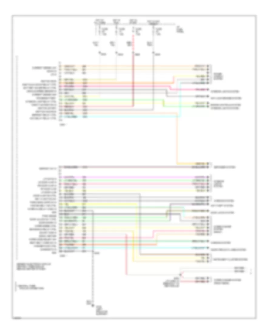
BODY COMPUTER
Body Computer Wiring Diagrams (1 of 2) for Ford Explorer 1998
 https://portal-diagnostov.com/license.html
Automotive Electricians Portal FZCO
Automotive Electricians Portal FZCO
https://portal-diagnostov.com/license.html
https://portal-diagnostov.com/license.html
Automotive Electricians Portal FZCO
Automotive Electricians Portal FZCOList of elements for Body Computer Wiring Diagrams (1 of 2) for Ford Explorer 1998:
- (front)
- (front-rear)
- * central timer
- Acc delay relay ctrl
- Anti-lock brakes system
- Anti-theft system
- Battery saver relay ctrl
- Brake/run relay ctrl
- C280
- C283
- Computer data lines system
- Current sense high
- Current sense low
- Defogger system
- Defrost relay ctrl
- Defrost sw in
- Diagnostic in
- Door ajar ind ctrl
- Door disarm in
- Door locks system
- Door unlock rly ctrl
- Down in
- Engine controls system
- Fasten belt ind ctrl
- Fuse 7.5a
- G108 (left radiator support)
- Generic electronic module/ central timer module (behind center of dash)
- Gnd
- Hot at all times
- Hot in acc or run
- Hot in run
- Hot in start
- I/p fuse panel
- Ignition (acc/run)
- Ignition (run)
- Ignition (start)
- Instrument cluster system
- Interior lamp relay ctrl
- Interior lights system
- Interval/delay wash in
- Key in ignition sw
- Lf door ajar
- Liftgate in
- Lr door ajar in
- Module connectors
- One-touch down relay ctrl
- Park sense
- Park/headlamps on in
- Power window system
- Power-battery
- Rf door ajar
- Rr door ajar in
- S232
- S242
- S244
- S245
- S250 (i/p harn, in breakout to gem module)
- S282
- Seat belt warn sw in
- Signal return
- Sound tone in
- Tan/red
- Throttle position in
- Up in
- Vehicle speed sensor in
- Warning system
- Washer pump ctrl
- Wiper mode select sw
- Wiper speed ctrl
- Wiper/washer system
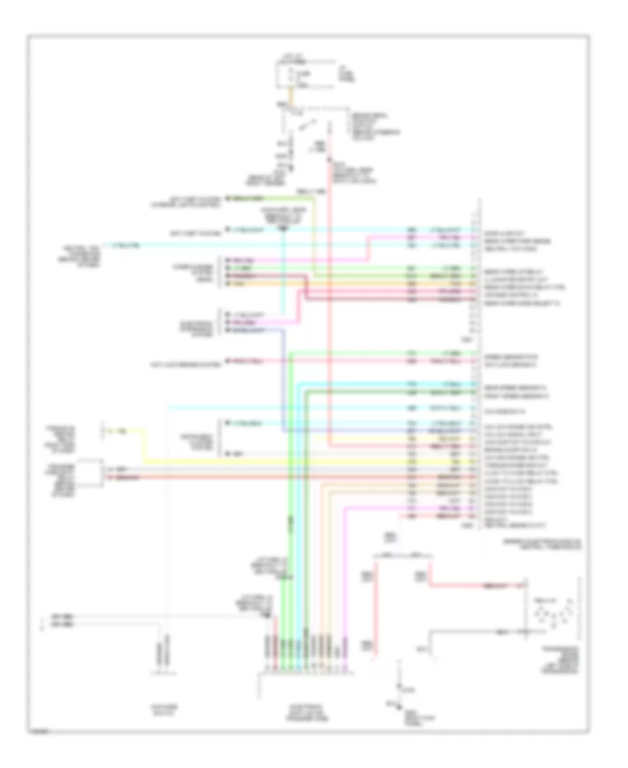
Body Computer Wiring Diagrams (2 of 2) for Ford Explorer 1998
 https://portal-diagnostov.com/license.html
Automotive Electricians Portal FZCO
Automotive Electricians Portal FZCO
https://portal-diagnostov.com/license.html
https://portal-diagnostov.com/license.html
Automotive Electricians Portal FZCO
Automotive Electricians Portal FZCOList of elements for Body Computer Wiring Diagrams (2 of 2) for Ford Explorer 1998:
- (i/p harn, in breakout to gem module) s251
- (i/p harn, in breakout to gem module) s252
- (main harn, near breakout to gem module) s258
- (rear)
- 4-high to 4-low relay ctrl
- 4-low to 4-high relay ctrl
- 4wd contact plate out
- 4wd mode switch
- 4x4 high range ind ctrl
- 4x4 low range ind cntrl
- 4x4 low signal input
- 4x4 mode sw in
- A/t
- Air ride control in
- Anti-lock brake in
- Anti-lock brakes system
- Anti-theft system
- Anti-theft system (interior lights control)
- Brake on/off sw in
- Brake pedal position switch (behind steering column)
- C281
- C282
- Contact plate a
- Contact plate b
- Contact plate c
- Contact plate d
- Door ajar out
- Electronic shift motor transfer case
- Electronic suspension system
- Front speed sensor in
- Fuse 7.5a
- G104 (rear of left front fender)
- G203 (right kick panel)
- Generic electronic module/ central timer module
- Gnd (m/t) neutral sense in (a/t)
- Hot at all times
- I/p fuse panel
- Illuminated entry out
- Instrument cluster system
- M/t
- Neutral tow conn
- Neutral tow connector (behind center of dash)
- Rear speed sensor in
- Rear wiper down relay ctrl
- Rear wiper mode select in
- Rear wiper park sense
- Rear wiper up relay
- S108
- S215 (i/p harn, near breakout to data link conn)
- S230
- Speed sensor pwr
- Tan
- Torque on demand relay (right side of dash)
- Torque-on-demand out
- Transfer case shift relay (behind center of dash)
- Transmission range sensor (left side of transmission)
- Wiper/washer system
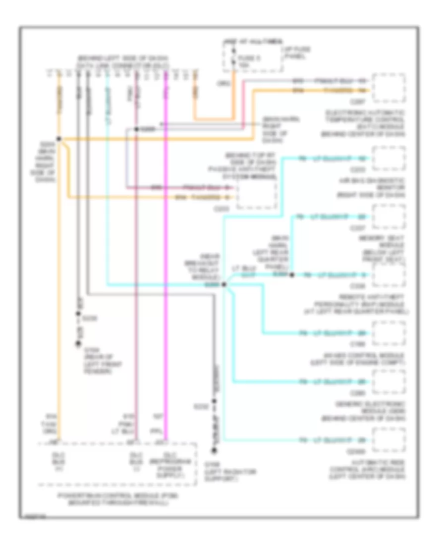
COMPUTER DATA LINES
Computer Data Lines for Ford Explorer 1998
 https://portal-diagnostov.com/license.html
Automotive Electricians Portal FZCO
Automotive Electricians Portal FZCO
https://portal-diagnostov.com/license.html
https://portal-diagnostov.com/license.html
Automotive Electricians Portal FZCO
Automotive Electricians Portal FZCOList of elements for Computer Data Lines for Ford Explorer 1998:
- (at left rear quarter panel)
- (behind left side of dash) data link connector (dlc)
- (behind top rt side of dash) passive anti-theft system module
- (main harn, left rear quarter panel) s304
- (main harn, right side of dash)
- (near breakout to relay module) s255
- 4wabs control module (left side of engine compt)
- Air bag diagnostic monitor (right side of dash)
- Automatic ride control (arc) module (left center of dash)
- C186
- C2000
- C233
- C280
- C297
- C336
- C337
- Dlc bus (+)
- Dlc bus (-)
- Electronic automatic temperature control (eatc) module (behind center of dash)
- Fuse 5 10a
- G104 (rear of left front fender)
- G108 (left radiator support)
- Generic electronic module (gem) (behind center of dash)
- Hot at all times
- I/p fuse panel
- Memory seat module (below left front seat)
- Powertrain control module (pcm) (mounted through firewall)
- Remote anti-theft personality (rap) module
- S205
- S206 (main harn, right side of dash)
- S230
- S232
CRUISE CONTROL
Cruise Control Wiring Diagram for Ford Explorer 1998
 https://portal-diagnostov.com/license.html
Automotive Electricians Portal FZCO
Automotive Electricians Portal FZCO
https://portal-diagnostov.com/license.html
https://portal-diagnostov.com/license.html
Automotive Electricians Portal FZCO
Automotive Electricians Portal FZCOList of elements for Cruise Control Wiring Diagram for Ford Explorer 1998:
- (w/ aux controls)
- (w/o aux controls)
- 4wabs control module (left side of engine compartment)
- A/t w/ high series console
- A/t w/o high series console
- Accel
- Back light
- Brake pedal position (bpp) switch (behind steering column)
- Brake press input
- Brake pressure switch (left rear corner of engine compt)
- C186
- C286
- C338
- Clockspring assembly (in steering column assembly)
- Clutch pedal position (cpp) switch (on clutch pedal arm)
- Clutch pedal position (cpp) switch jumper (left side of dash, taped to main harness)
- Coast
- Fuse 10 15a
- Fuse 20a
- Fuse 7.5a
- G104 (rear of left front fender)
- G105 (rear of right front fender)
- G108 (left radiator support)
- Ground
- Headlamp switch
- Horn relay (in power distri- bution box)
- Horn switches
- Hot at all times
- Hot in run
- I/p fuse panel
- Ignition
- Indicator control
- Instrument cluster
- Interior lights system
- M/t
- Nca
- Off
- Ohms
- Pnk
- Power distribution box
- Rear axle sensor (on axle assembly)
- Red/
- Red/ lt grh
- Remote anti-theft personality (rap) module (at left rear quarter panel)
- Resume
- S161
- S168 (near breakout to 4wabs control module)
- S215 (near breakout to ignition switch)
- S230
- S232
- S244
- Set/
- Speed cont sw gnd
- Speed cont sw in
- Speed control indicator lamp
- Speed control servo/ amplifier assembly (in right rear of engine compartment)
- Vehicle speed input
DEFOGGERS
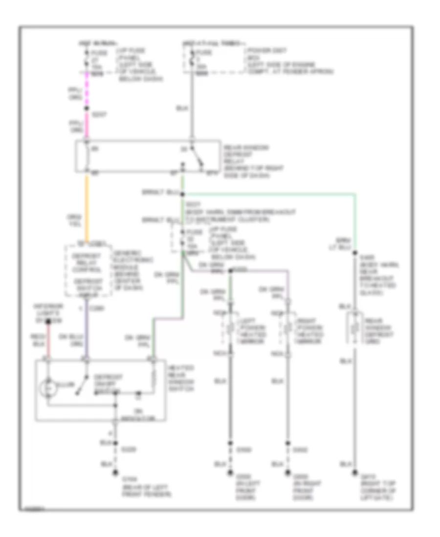
Defogger Wiring Diagram for Ford Explorer 1998
 https://portal-diagnostov.com/license.html
Automotive Electricians Portal FZCO
Automotive Electricians Portal FZCO
https://portal-diagnostov.com/license.html
https://portal-diagnostov.com/license.html
Automotive Electricians Portal FZCO
Automotive Electricians Portal FZCOList of elements for Defogger Wiring Diagram for Ford Explorer 1998:
- (rear of left front fender)
- 87a
- C280
- C283
- Defrost on/off switch
- Defrost relay control
- Defrost switch input
- Fuse 10a mini
- Fuse 15a mini
- Fuse 30a mini
- G104
- G410 (right top corner of liftgate)
- G500 (in left front door)
- G600 (in right front door)
- Generic electronic module (behind center of dash)
- Heated rear window switch
- Hot at all times
- Hot in run
- I/p fuse panel (left side of vehicle, below dash)
- Illum
- Interior lights system
- Left power/ heated mirror
- Nca
- On indicator
- Power dist box (left side of engine compt, at fender apron)
- Rear window defrost grid
- Rear window defrost relay (behind top right side of dash)
- Right power/ heated mirror
- S207
- S221
- S222
- S229
- S405 (body harn, near breakout to heated glass)
- S500
- S602
ELECTRONIC SUSPENSION
Electronic Suspension Wiring Diagram (1 of 2) for Ford Explorer 1998
 https://portal-diagnostov.com/license.html
Automotive Electricians Portal FZCO
Automotive Electricians Portal FZCO
https://portal-diagnostov.com/license.html
https://portal-diagnostov.com/license.html
Automotive Electricians Portal FZCO
Automotive Electricians Portal FZCOList of elements for Electronic Suspension Wiring Diagram (1 of 2) for Ford Explorer 1998:
- (i/p harn, near breakout to inst cluster)
- (main harn, near breakout to arc module)
- (near breakout to relay module)
- (rear of left left front fender)
- 4wabs control module (left side of engine compt)
- 4x4 high sig
- 4x4 low sig
- Arc accel sig
- Arc compr rly
- Arc off/on sw
- Automatic ride control (arc) module (left center of dash)
- Automatic ride control compressor assembly (at rear of vehicle)
- Automatic ride control off/on switch (rear of vehicle)
- Automatic ride control relay
- Auxiliary relay box 1 (left side of engine compartment)
- Brake on/off sw
- C2000
- C2001
- Comp vent sol
- Data link connector (left side of dash)
- Door ajar in
- Front fill sol
- Fuse 8 20a
- Fuse 9 40a
- G104
- G104 (rear of left front fender)
- G105 (rear of right front fender)
- G108 (left radiator support)
- G200 (left kick panel)
- Gnd
- Height sen power
- Hot at all times
- Iso link
- Left front shock actuator (at left front shock)
- Left rear shock actuator (at left rear shock)
- Lf height sen
- Lf shock actuator
- Lf shock pos in
- Lr shock actuator
- Lr shock pos in
- Nca
- Pcm accel sig
- Pnk
- Power (hot in run)
- Power distribution box
- Powertrain control module (pcm) (mounted through firewall)
- Rear fill sol
- Rear gate sol
- Rear height sen
- Red
- Rf shock actuator
- Rf shock pos in
- Right front shock actuator (at right front shock)
- Right rear shock actuator (at right rear shock)
- Rr shock actuator
- Rr shock pos in
- S153
- S161
- S230
- S232
- S247
- S253
- S255
- S351
- Steering rate sensor (in steering column)
- Steering sensor
- Vss (+)
- Warning sig
Electronic Suspension Wiring Diagram (2 of 2) for Ford Explorer 1998
 https://portal-diagnostov.com/license.html
Automotive Electricians Portal FZCO
Automotive Electricians Portal FZCO
https://portal-diagnostov.com/license.html
https://portal-diagnostov.com/license.html
Automotive Electricians Portal FZCO
Automotive Electricians Portal FZCOList of elements for Electronic Suspension Wiring Diagram (2 of 2) for Ford Explorer 1998:
- (in main harn, near gem breakout)
- Brake on/off switch (on brake pedal)
- C2008
- C2009
- C281
- C282
- C336
- Front fill solenoid (left rear corner of engine compt)
- Fuse 1o 7.5a
- Fuse 9 7.5a
- G104 (rear of left front fender)
- G108 (left radiator support)
- G200 (left kick panel)
- Generic electronic module (gem) (behind center of dash)
- Hot at all times
- Hot in run
- I/p fuse panel
- Left front height sensor (at left front shock)
- Message center (in instrument panel console)
- Rear fill solenoid (on rear axle)
- Rear gate solenoid (left rear corner of vehicle)
- Rear height sensor (left rear corner of vehicle)
- Red/
- Remote anti-theft personality (rap) module (left rear quarter panel)
- S137
- S215 (i/p harn, near breakout to ignition switch)
- S230
- S234
- S241
- S256 (i/p harn, near breakout to inst cluster)
- S258
- S351
ENGINE PERFORMANCE
4.0L
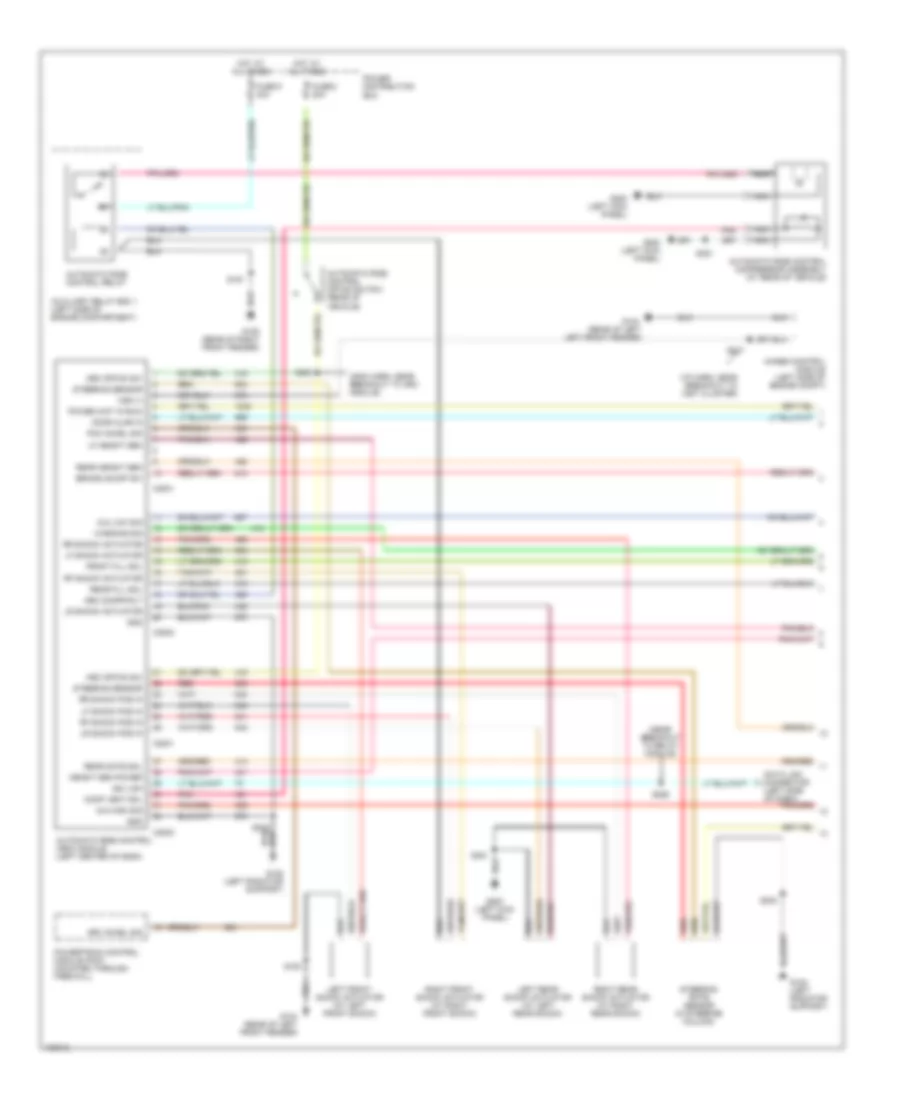
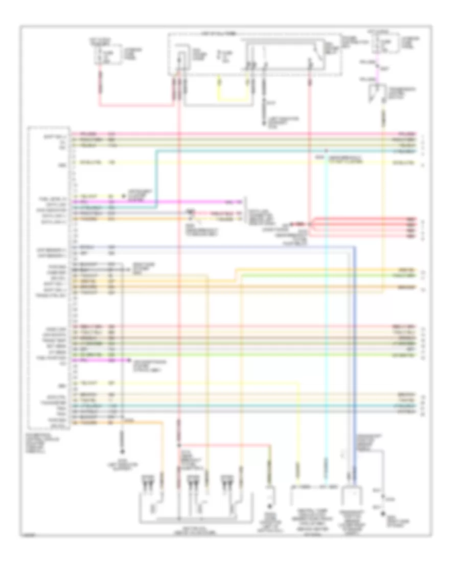
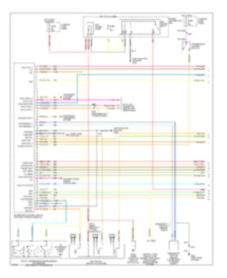
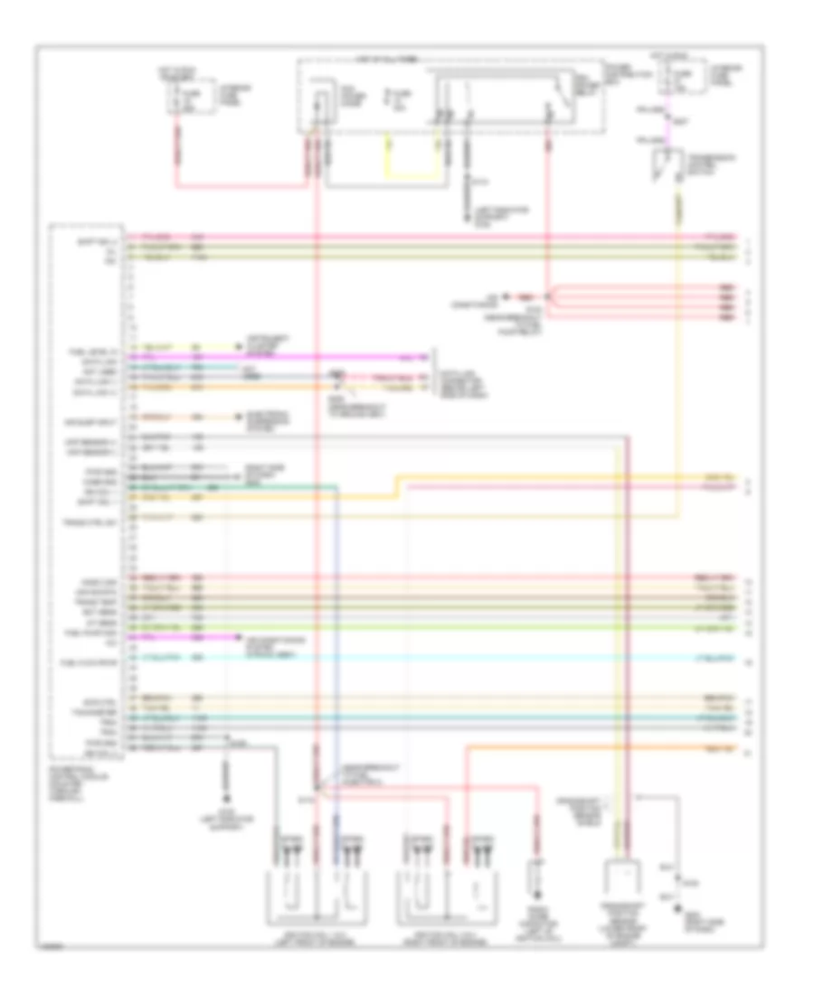
4.0L OHV, Engine Performance Wiring Diagrams (1 of 4) for Ford Explorer 1998
 https://portal-diagnostov.com/license.html
Automotive Electricians Portal FZCO
Automotive Electricians Portal FZCO
https://portal-diagnostov.com/license.html
https://portal-diagnostov.com/license.html
Automotive Electricians Portal FZCO
Automotive Electricians Portal FZCOList of elements for 4.0L OHV, Engine Performance Wiring Diagrams (1 of 4) for Ford Explorer 1998:
- (behind center
- (left radiator support) g108
- (near breakout to inst cluster)
- (right side of dash) g203
- A/c
- Air conditioning
- Air conditioning system (htr-a/c assy)
- Awd indicator
- C282
- C283
- Case gnd
- Central timer module (ctm)/ generic electronic module (gem)
- Ckp sensor (+)
- Ckp sensor (-)
- Crankshaft position sensor (lower front of engine compt)
- Crankshaft position sensor shield
- Data link
- Data link (+)
- Data link (-)
- Data link connector (behind left side of dash)
- Ect sens
- Evr ctrl
- Fuel level in
- Fuel pump mon
- Fuse 15a
- Fuse 25a
- Fuse 30a
- G108 (left radiator support)
- G203 (right side of dash)
- Gem
- Ho2s 2 sig
- Hot at all times
- Hot in run
- Hot in run or start
- Iat sens
- Ign coil
- Ignition coil (above valve cover)
- Instrument cluster system
- Interior fuse panel
- Maf sig rtn
- Mil
- Of dash)
- Oss
- Pcm power diode
- Pcm power relay
- Power distribution box
- Powertrain control module (mounted through firewall)
- Pwr gnd
- Radio noise capacitor (left of ignition coil)
- Red
- S105
- S108
- S118 (near breakout to fuel injector 3)
- S123 (near breakout to fuel pump relay)
- S205
- S206 (near breakout to ground g901)
- S207
- S248
- Shift sol 1
- Shift sol 2
- Shift sol 4
- Spark plugs
- Tachometer
- Tr1
- Tr2a
- Tr4a
- Trans ctrl sw
- Trans temp
- Transmission control switch
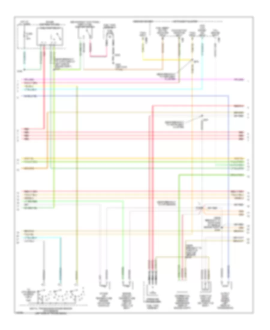
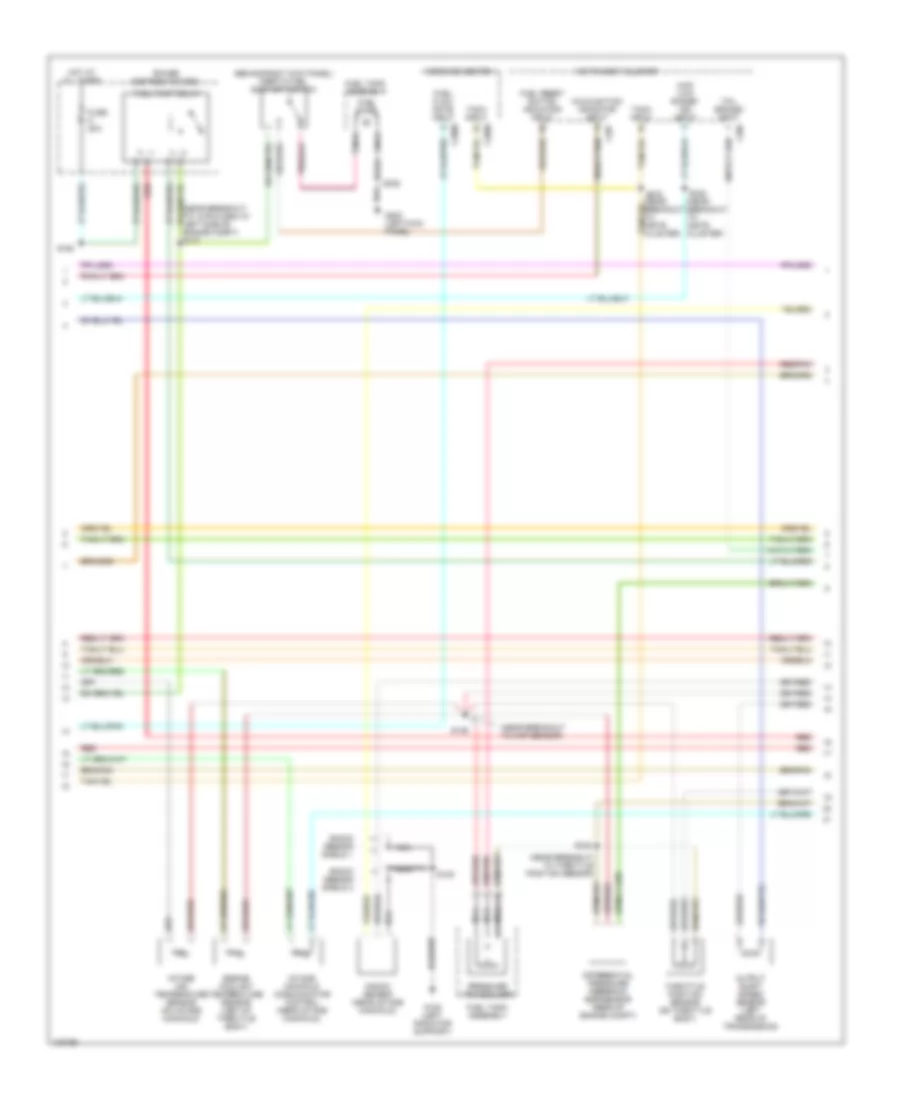
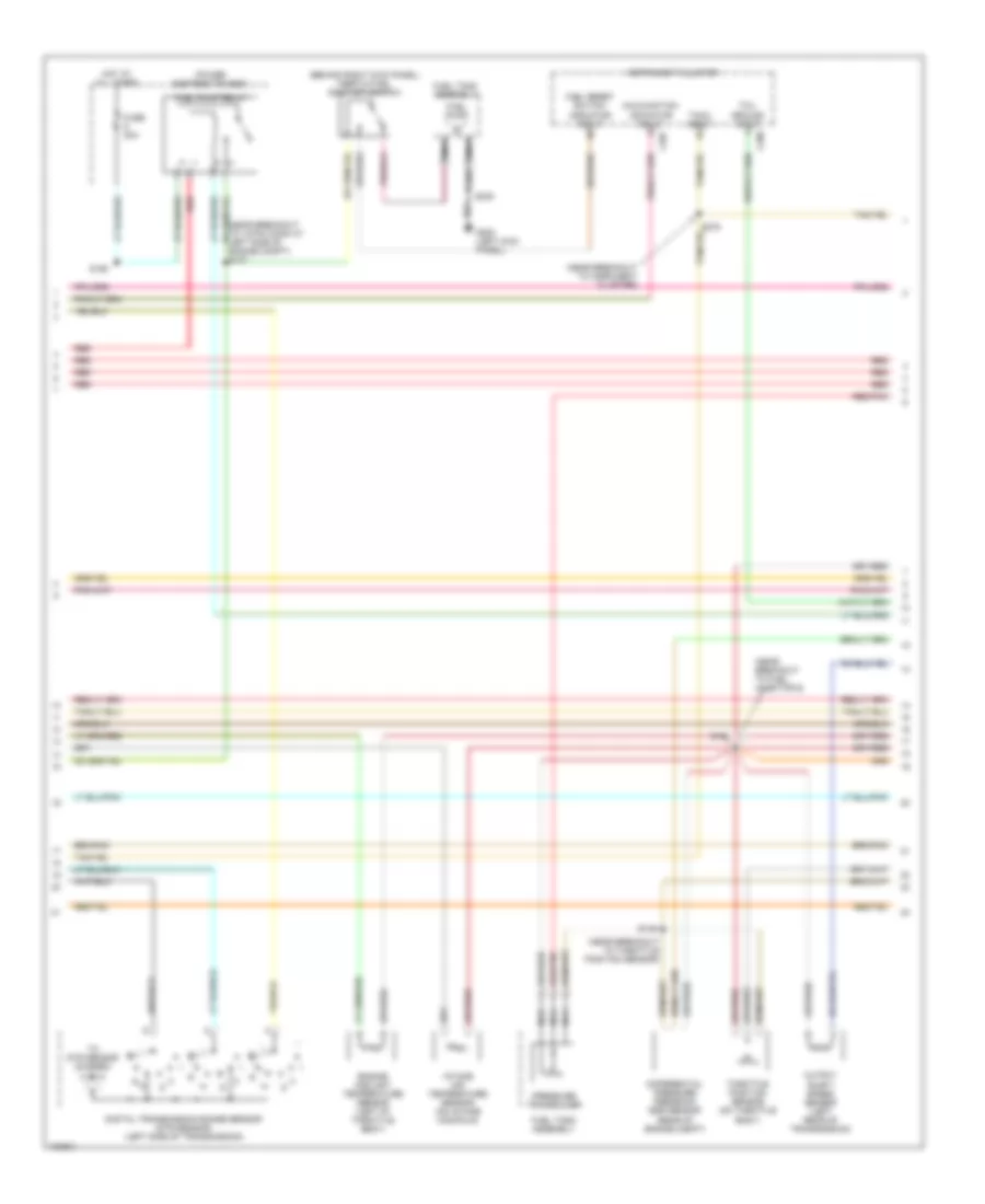
4.0L OHV, Engine Performance Wiring Diagrams (2 of 4) for Ford Explorer 1998
 https://portal-diagnostov.com/license.html
Automotive Electricians Portal FZCO
Automotive Electricians Portal FZCO
https://portal-diagnostov.com/license.html
https://portal-diagnostov.com/license.html
Automotive Electricians Portal FZCO
Automotive Electricians Portal FZCOList of elements for 4.0L OHV, Engine Performance Wiring Diagrams (2 of 4) for Ford Explorer 1998:
- (behind right kick panel) inertia fuel shut-off switch
- (near breakout to 12-pin conn at left side of engine compt) s127
- (near breakout to 16-pin conn at rear of engine compt)
- (near breakout to insrument cluster)
- (near breakout to instrument cluster)
- (near breakout to map sensor)
- (near breakout to throttle position sensor) s146
- 4wd "low range" ind input
- C2009
- C286
- C287
- Differential pressure feedback egr sensor (rear of engine compt)
- Digital transmission range sensor (dtr sensor) (left side of transmission)
- Engine coolant temperature sensor (left of throttle body)
- Fuel pump
- Fuel pump relay
- Fuel reset switch indicator input
- Fuel tank assembly
- Fuse 20a
- G200 (left kick panel)
- Hot at all times
- Instrument cluster
- Intake air temperature sensor (on intake manifold)
- Malfunction indicator input
- Message center
- Nca
- Output shaft speed sensor (left rear of transmission)
- Power distribution box
- Pressure transducer
- R n
- Red
- Red/pnk
- S136
- S160
- S180
- S201
- S235
- S275
- Tach input
- Tcil ground input
- Throttle position sensor (on throttle body)
- To dtr sensor (diagram 4 of 4)
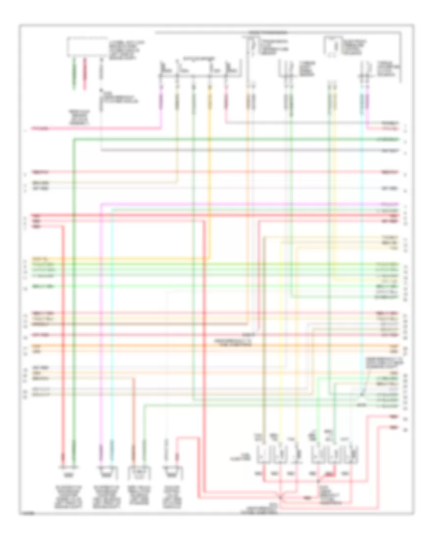
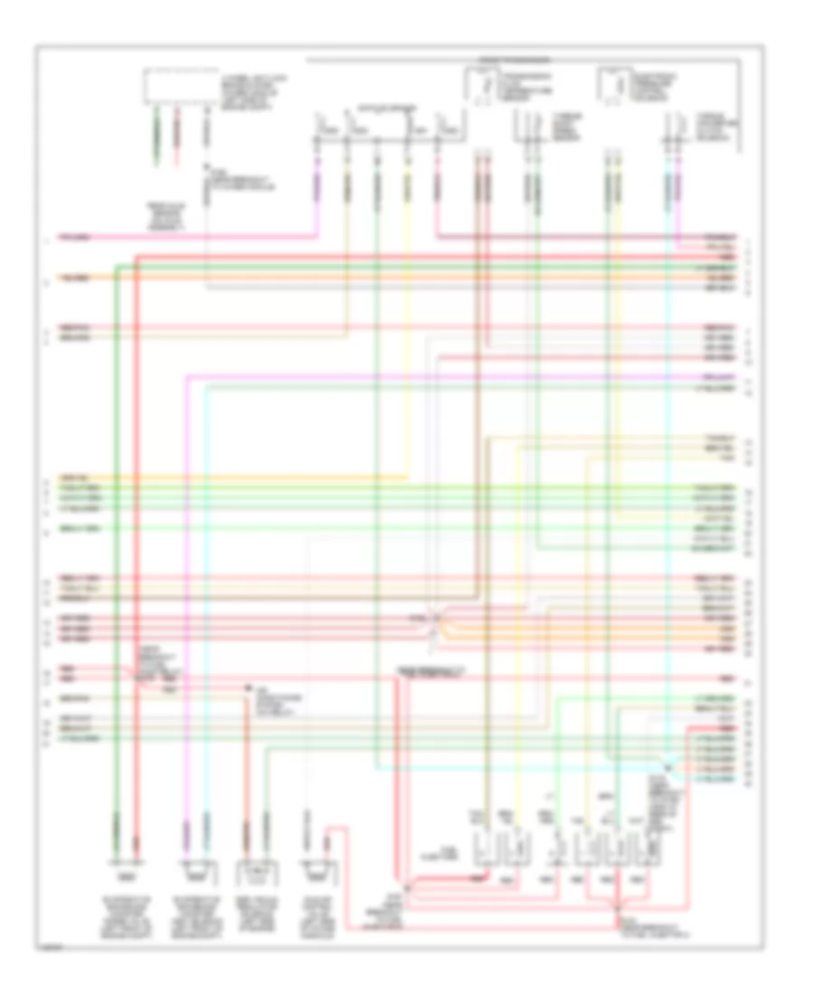
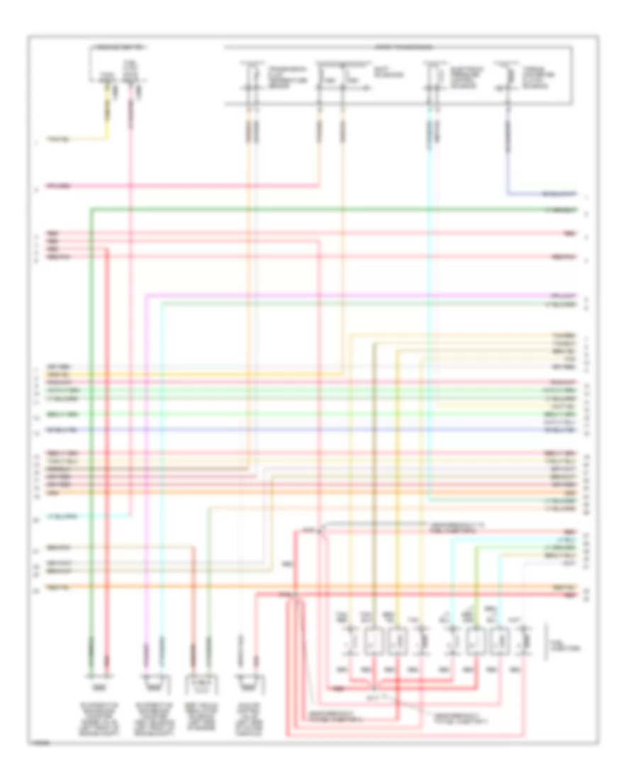
4.0L OHV, Engine Performance Wiring Diagrams (3 of 4) for Ford Explorer 1998
 https://portal-diagnostov.com/license.html
Automotive Electricians Portal FZCO
Automotive Electricians Portal FZCO
https://portal-diagnostov.com/license.html
https://portal-diagnostov.com/license.html
Automotive Electricians Portal FZCO
Automotive Electricians Portal FZCOList of elements for 4.0L OHV, Engine Performance Wiring Diagrams (3 of 4) for Ford Explorer 1998:
- (near breakout to 16-pin conn at rear of engine compt)
- (near breakout to fuel injector 6)
- 4 wheel anti-lock brake system (4wabs) module (left side of engine compt)
- 5r55e transmission
- Egr vacuum regulator solenoid (left side of engine)
- Electronic pressure control solenoid
- Evaporative emmissions canister purge valve (left front of engine compt)
- Evaporative emmissions canister vent solenoid (left front of engine compt)
- Fuel injectors
- Idle air control valve (left side of intake manifold)
- Rear axle sensor (on axle assembly)
- Red
- Red/pnk
- S124 (near breakout to fuel injector 4)
- S166
- S167 (near breakout to fuel injector 6)
- S179
- Shift solenoids
- Ss1
- Ss2
- Ss3
- Ss4
- Tan
- To 4wabs module)
- Torque converter clutch solenoid
- Transmission fluid temperature sensor
- Turbine shaft speed sensor
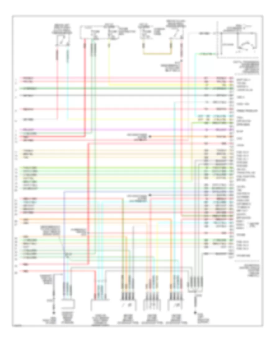
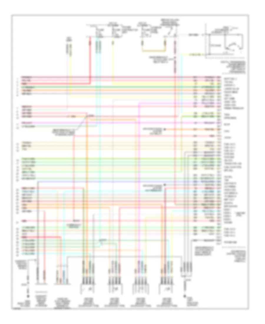
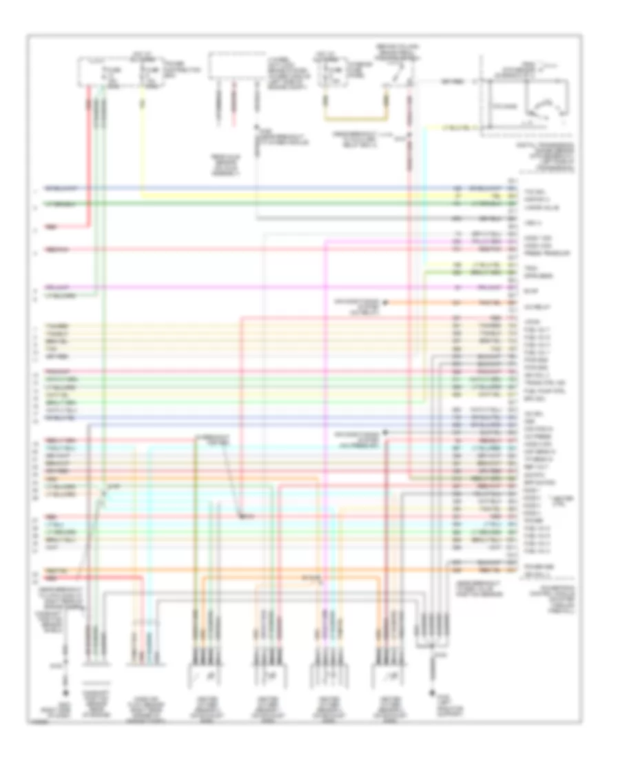
4.0L OHV, Engine Performance Wiring Diagrams (4 of 4) for Ford Explorer 1998
 https://portal-diagnostov.com/license.html
Automotive Electricians Portal FZCO
Automotive Electricians Portal FZCO
https://portal-diagnostov.com/license.html
https://portal-diagnostov.com/license.html
Automotive Electricians Portal FZCO
Automotive Electricians Portal FZCOList of elements for 4.0L OHV, Engine Performance Wiring Diagrams (4 of 4) for Ford Explorer 1998:
- (a/t)
- (behind column) brake pedal position switch
- (behind left side of dash) clutch pedal position switch
- (in breakout for pcm) s101
- (m/t)
- (near breakout to 4-pin conn at right rear of engine compt)
- 270 ohms
- A/c press
- Air conditioning system (a/c press sw)
- Air conditioning system (a/c relay)
- Bpp switch
- Cam pos in
- Camshaft position sensor (rear of engine)
- Camshaft position sensor shield
- Cpp switch
- Digital transmission range sensor (dtr sensor-a/t) (left side of transmission)
- Dpfe sens
- Epc sol
- Evap
- From dtr sensor (diagram 2 of 4)
- Fuel inj 1
- Fuel inj 2
- Fuel inj 3
- Fuel inj 4
- Fuel inj 5
- Fuel inj 6
- Fuel pump ctrl
- Fuse 10a (mini)
- Fuse 15a (mini)
- Fuse 7.5a
- G108 (left radiator support)
- G203 (right side of dash)
- Heated oxygen sensor 1 (on exhaust pipe)
- Heated oxygen sensor 2 (on exhaust pipe)
- Heated oxygen sensor 3 (on exhaust pipe)
- Heater ctrl
- Ho2s 1
- Ho2s 1 sig
- Ho2s 2
- Ho2s 2 sig
- Ho2s 3
- Hot at all times
- Iac sol
- Ign coil
- Interior fuse panel
- Kapwr (+)
- Maf sens in
- Mass air flow sensor (right rear corner of engine compt)
- Nca
- Power
- Power distribution box
- Power gnd
- Powertrain control module (mounted through firewall)
- Press trnsducr
- Pwr gnd
- Red
- Red/pnk
- Ref volt
- S105
- S108
- S142
- S147 (near breakout to auxiliary relay box 3)
- Shift sol 3
- Sig rtn
- Tan
- Tcc sol
- Tp sens in
- Tr3a
- Trans ctrl ind
- Tss
- Vapor valve
- Vpwr
- Vss (+)
- Wac
4.0L SOHC, Engine Performance Wiring Diagrams (1 of 4) for Ford Explorer 1998
 https://portal-diagnostov.com/license.html
Automotive Electricians Portal FZCO
Automotive Electricians Portal FZCO
https://portal-diagnostov.com/license.html
https://portal-diagnostov.com/license.html
Automotive Electricians Portal FZCO
Automotive Electricians Portal FZCOList of elements for 4.0L SOHC, Engine Performance Wiring Diagrams (1 of 4) for Ford Explorer 1998:
- (left radiator support) g108
- (right side of dash)
- A/c
- Air conditioning system (htr-a/c assy)
- Air susp input
- Awd indicator
- C283
- Case gnd
- Central timer module (ctm)/ generic electronic module (gem) (behind center of dash)
- Ckp sensor (+)
- Ckp sensor (-)
- Crankshaft position sensor (lower front of engine compt)
- Crankshaft position sensor shield
- Data link
- Data link (+)
- Data link (-)
- Data link connector (behind left side of dash)
- Digital transmission range sensor (dtr sensor) (left side of transmission)
- Ect sens
- Electronic suspension system
- Evr ctrl
- Fuel flow rate
- Fuel level in
- Fuel pump mon
- Fuse 15a
- Fuse 25a
- Fuse 30a
- G203
- G203 (right side of dash)
- Gem
- Ho2s 2 sig
- Hot at all times
- Hot in run
- Hot in run or start
- Iat sens
- Ign coil
- Ignition coil (above valve cover)
- Imcc
- Instrument cluster system
- Interior fuse panel
- Maf sig rtn
- Mil
- Oss
- Pcm power diode
- Pcm power relay
- Power distribution box
- Powertrain control module (mounted through firewall)
- Pwr gnd
- R n
- Radio noise capacitor (left of ignition coil)
- Red
- S105
- S108
- S118 (near breakout to fuel injector 3)
- S205
- S206 (near breakout to ground g901)
- S207
- Shift sol 1
- Shift sol 2
- Shift sol 4
- Spark plugs
- Tachometer
- To dtr sensor (diagram 4 of 4)
- Tr1
- Tr2a
- Tr4a
- Trans ctrl sw
- Trans temp
- Transmission control switch
4.0L SOHC, Engine Performance Wiring Diagrams (2 of 4) for Ford Explorer 1998
 https://portal-diagnostov.com/license.html
Automotive Electricians Portal FZCO
Automotive Electricians Portal FZCO
https://portal-diagnostov.com/license.html
https://portal-diagnostov.com/license.html
Automotive Electricians Portal FZCO
Automotive Electricians Portal FZCOList of elements for 4.0L SOHC, Engine Performance Wiring Diagrams (2 of 4) for Ford Explorer 1998:
- (behind right kick panel) inertia fuel shut-off switch
- (near breakout to 12-pin conn at left side of engine compt) s127
- (near breakout to instr cluster)
- (near breakout to map sensor)
- (near breakout to throttle position sensor)
- 4wd "low range" ind input
- C2008
- C2009
- Differential pressure feedback egr sensor (rear of engine compt)
- Engine coolant temperature sensor (left of throttle body)
- Fuel flow rate input
- Fuel pump
- Fuel pump relay
- Fuel reset switch indicator input
- Fuel tank assembly
- Fuse 20a
- G108 (left radiator support)
- G200 (left kick panel)
- Hot at all times
- Instrument cluster
- Intake air temperature sensor (on intake manifold)
- Intake manifold communicator control (near intake manifold)
- Knock sensor (near intake manifold)
- Knock sensor shield 1
- Knock sensor shield 2
- Malfunction indicator input
- Message center
- Nca
- Output shaft speed sensor (left rear of transmission)
- Power distribution box
- Pressure transducer
- Red
- Red/pnk
- S105
- S136
- S146
- S160
- S235
- S248
- Tach input
- Tcil ground input
- Throttle position sensor (on throttle body)
4.0L SOHC, Engine Performance Wiring Diagrams (3 of 4) for Ford Explorer 1998
 https://portal-diagnostov.com/license.html
Automotive Electricians Portal FZCO
Automotive Electricians Portal FZCO
https://portal-diagnostov.com/license.html
https://portal-diagnostov.com/license.html
Automotive Electricians Portal FZCO
Automotive Electricians Portal FZCOList of elements for 4.0L SOHC, Engine Performance Wiring Diagrams (3 of 4) for Ford Explorer 1998:
- (near breakout to fuel injector 6)
- (near breakout to fuel pump relay) s123
- 4 wheel anti-lock brake system (4wabs) module (left side of engine compt)
- 5r55e transmission
- Air conditioning system (a/c relay)
- Egr vacuum regulator solenoid (left side of engine)
- Electronic pressure control solenoid
- Evaporative emmissions canister purge valve (left front of engine compt)
- Evaporative emmissions canister vent solenoid (left front of engine compt)
- Fuel injectors
- Idle air control valve (left side of intake manifold)
- Rear axle sensor (on axle assembly)
- Red
- Red/pnk
- S124 (near breakout to fuel injector 4)
- S166
- S167
- Shift solenoids
- Ss1
- Ss2
- Ss3
- Ss4
- Tan
- To 4wabs module)
- Torque converter clutch solenoid
- Transmission fluid temperature sensor
- Turbine shaft speed sensor
4.0L SOHC, Engine Performance Wiring Diagrams (4 of 4) for Ford Explorer 1998
 https://portal-diagnostov.com/license.html
Automotive Electricians Portal FZCO
Automotive Electricians Portal FZCO
https://portal-diagnostov.com/license.html
https://portal-diagnostov.com/license.html
Automotive Electricians Portal FZCO
Automotive Electricians Portal FZCOList of elements for 4.0L SOHC, Engine Performance Wiring Diagrams (4 of 4) for Ford Explorer 1998:
- (behind column) brake pedal position switch
- (in breakout for pcm)
- (near breakout to 16-pin conn at rear of engine compt)
- (near breakout to 4-pin conn at right rear of engine compt)
- (near breakout to auxiliary relay box 3)
- 270 ohms
- A/c press
- Air conditioning system (a/c press sw)
- Air conditioning system (a/c relay)
- Bpp switch
- Cam pos in
- Camshaft position sensor (rear of engine)
- Camshaft position sensor shield
- Digital transmission range sensor (dtr sensor-a/t) (left side of transmission)
- Dpfe sens
- Epc sol
- Evap
- From dtr sensor (diagram 1 of 4)
- Fuel inj 1
- Fuel inj 2
- Fuel inj 3
- Fuel inj 4
- Fuel inj 5
- Fuel inj 6
- Fuel pump ctrl
- Fuse 10a (mini)
- Fuse 15a (mini)
- Fuse 7.5a
- G108 (left radiator support)
- G203 (right side of dash)
- Heated oxygen sensor 1 (on exhaust pipe)
- Heated oxygen sensor 2 (on exhaust pipe)
- Heated oxygen sensor 3 (on exhaust pipe)
- Heated oxygen sensor 4 (on exhaust pipe)
- Heater ctrl
- Ho2s 1
- Ho2s 1 sig
- Ho2s 2
- Ho2s 2 sig
- Ho2s 3
- Ho2s 4
- Ho2s 4 sig
- Hot at all times
- Iac sol
- Ign coil
- Interior fuse panel
- Kapwr (+)
- Knock sens
- Maf sens in
- Mass air flow sensor (right rear corner of engine compt)
- Nca
- Not used
- Power
- Power distribution box
- Power gnd
- Powertrain control module (mounted through firewall)
- Press trnsducr
- Pwr gnd
- Red
- Red/pnk
- Ref volt
- S101
- S105
- S108
- S142
- S180
- Shift sol 3
- Sig rtn
- Tan
- Tcc sol
- Tp sens in
- Tr3a
- Trans ctrl ind
- Tss
- Vapor valve
- Vpwr
- Vss (+)
- Wac
5.0L
5.0L, Engine Performance Wiring Diagrams (1 of 4) for Ford Explorer 1998
 https://portal-diagnostov.com/license.html
Automotive Electricians Portal FZCO
Automotive Electricians Portal FZCO
https://portal-diagnostov.com/license.html
https://portal-diagnostov.com/license.html
Automotive Electricians Portal FZCO
Automotive Electricians Portal FZCOList of elements for 5.0L, Engine Performance Wiring Diagrams (1 of 4) for Ford Explorer 1998:
- (left radiator support) g108
- (near breakout to fuel injector 3)
- (right side of dash) g203
- A/c
- Air conditioning
- Air conditioning system (htr-a/c assy)
- Air susp input
- Case gnd
- Ckp sensor (+)
- Ckp sensor (-)
- Crankshaft position sensor (lower front of engine compt)
- Crankshaft position sensor shield
- Data link
- Data link (+)
- Data link (-)
- Data link connector (behind left side of dash)
- Ect sens
- Electronic suspension system
- Evr ctrl
- Fuel flow rate
- Fuel level in
- Fuel pump mon
- Fuse 15a
- Fuse 25a
- Fuse 30a
- G108 (left radiator support)
- G203 (right side of dash)
- Ho2s 2 sig
- Hot at all times
- Hot in run
- Hot in run or start
- Iat sens
- Ign coil 1
- Ign coil 2
- Ignition coil 1 & 2 (left front of engine)
- Ignition coil 3 & 4 (right front of engine)
- Instrument cluster system
- Interior fuse panel
- Maf sig rtn
- Mil
- Not used
- Pcm power diode
- Pcm power relay
- Power distribution box
- Powertrain control module (mounted through firewall)
- Pwr gnd
- Radio noise capacitor (left of ignition coil)
- Red
- S105
- S108
- S118
- S123 (near breakout to fuel pump relay)
- S205
- S206 (near breakout to ground g901)
- S207
- Shift sol 1
- Shift sol 2
- Spark plugs
- Tachometer
- Tr1
- Tr2a
- Tr4a
- Trans ctrl sw
- Trans temp
- Transmission control switch
5.0L, Engine Performance Wiring Diagrams (2 of 4) for Ford Explorer 1998
 https://portal-diagnostov.com/license.html
Automotive Electricians Portal FZCO
Automotive Electricians Portal FZCO
https://portal-diagnostov.com/license.html
https://portal-diagnostov.com/license.html
Automotive Electricians Portal FZCO
Automotive Electricians Portal FZCOList of elements for 5.0L, Engine Performance Wiring Diagrams (2 of 4) for Ford Explorer 1998:
- (behind right kick panel) inertia fuel shut-off switch
- (near breakout to 12-pin conn at left side of engine compt) s127
- (near breakout to fuel injector 6)
- (near breakout to insrument cluster)
- (near breakout to throttle position sensor)
- C286
- C287
- Differential pressure feedback egr sensor (rear of engine compt)
- Digital transmission range sensor (dtr sensor) (left side of transmission)
- Engine coolant temperature sensor (left of throttle body)
- Fuel pump
- Fuel pump relay
- Fuel reset switch indicator input
- Fuel tank assembly
- Fuse 20a
- G200 (left kick panel)
- Hot at all times
- Instrument cluster
- Intake air temperature sensor (on intake manifold)
- Malfunction indicator input
- Nca
- Output shaft speed sensor (left rear of transmission)
- Power distribution box
- Pressure transducer
- R n
- Red
- Red/pnk
- S146
- S160
- S166
- S235
- Tach input
- Tcil ground input
- Throttle position sensor (on throttle body)
- To dtr sensor (diagram 4 of 4)
5.0L, Engine Performance Wiring Diagrams (3 of 4) for Ford Explorer 1998
 https://portal-diagnostov.com/license.html
Automotive Electricians Portal FZCO
Automotive Electricians Portal FZCO
https://portal-diagnostov.com/license.html
https://portal-diagnostov.com/license.html
Automotive Electricians Portal FZCO
Automotive Electricians Portal FZCOList of elements for 5.0L, Engine Performance Wiring Diagrams (3 of 4) for Ford Explorer 1998:
- (near breakout to fuel injector 4)
- (near breakout to fuel injector 6)
- (near breakout to fuel injector 7)
- 4r7ow transmission
- C2008
- C2009
- Egr vacuum regulator solenoid (left side of engine)
- Electronic pressure control solenoid
- Evaporative emmissions canister purge valve (left front of engine compt)
- Evaporative emmissions canister vent solenoid (left front of engine compt)
- Fuel flow rate input
- Fuel injectors
- Idle air control valve (left side of intake manifold)
- Message center
- Red
- Red/pnk
- S117
- S124
- S167
- Shift solenoids
- Ss1
- Ss2
- Tach input
- Tan
- Tan/ red
- Tan/red
- Torque converter clutch solenoid
- Transmission fluid temperature sensor
5.0L, Engine Performance Wiring Diagrams (4 of 4) for Ford Explorer 1998
 https://portal-diagnostov.com/license.html
Automotive Electricians Portal FZCO
Automotive Electricians Portal FZCO
https://portal-diagnostov.com/license.html
https://portal-diagnostov.com/license.html
Automotive Electricians Portal FZCO
Automotive Electricians Portal FZCOList of elements for 5.0L, Engine Performance Wiring Diagrams (4 of 4) for Ford Explorer 1998:
- (behind column) brake pedal position switch
- (in breakout for pcm)
- (near breakout to 4-pin conn at right rear of engine compt)
- (near breakout to auxiliary relay box 3)
- (near breakout to egr valve position sensor)
- 270 ohms
- 4 wheel anti-lock brake system (4wabs) module (left side of engine compt)
- A/c press
- A/c relay
- Air conditioning system (a/c press sw)
- Air conditioning system (a/c relay)
- Bpp switch
- Cam pos in
- Camshaft position sensor (rear of engine)
- Camshaft position sensor shield
- Digital transmission range sensor (dtr sensor-a/t) (left side of transmission)
- Dpfe sens
- Epc sol
- Evap
- From dtr sensor (diagram 2 of 4)
- Fuel inj 1
- Fuel inj 2
- Fuel inj 3
- Fuel inj 4
- Fuel inj 5
- Fuel inj 6
- Fuel inj 7
- Fuel inj 8
- Fuel pump ctrl
- Fuse 10a (mini)
- Fuse 15a (mini)
- Fuse 7.5a
- G108 (left radiator support)
- G203 (right side of dash)
- Heated oxygen sensor 1 (on exhaust pipe)
- Heated oxygen sensor 2 (on exhaust pipe)
- Heated oxygen sensor 3 (on exhaust pipe)
- Heated oxygen sensor 4 (on exhaust pipe)
- Heater ctrl
- Ho2s 1
- Ho2s 1 sig
- Ho2s 2
- Ho2s 2 sig
- Ho2s 3
- Ho2s 4
- Ho2s 4 sig
- Hot at all times
- Iac sol
- Ign coil 3
- Ign coil 4
- Interior fuse panel
- Kapwr (+)
- Maf sens in
- Mass air flow sensor (right rear corner of engine compt)
- Nca
- Oss
- Power
- Power distribution box
- Power gnd
- Powertrain control module (mounted through firewall)
- Press trnsducr
- Pwr gnd
- Rear axle sensor (on axle assembly)
- Red
- Red/pnk
- Ref volt
- S101
- S105
- S108
- S119
- S142
- Sig rtn
- Tan
- Tan/red
- Tcc sol
- To 4wabs module)
- Tp sens in
- Tr3a
- Trans ctrl ind
- Vapor valve
- Vpwr
- Vss (+)
EXTERIOR LIGHTS
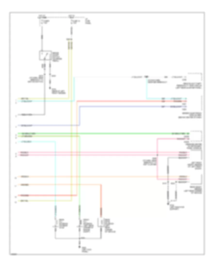
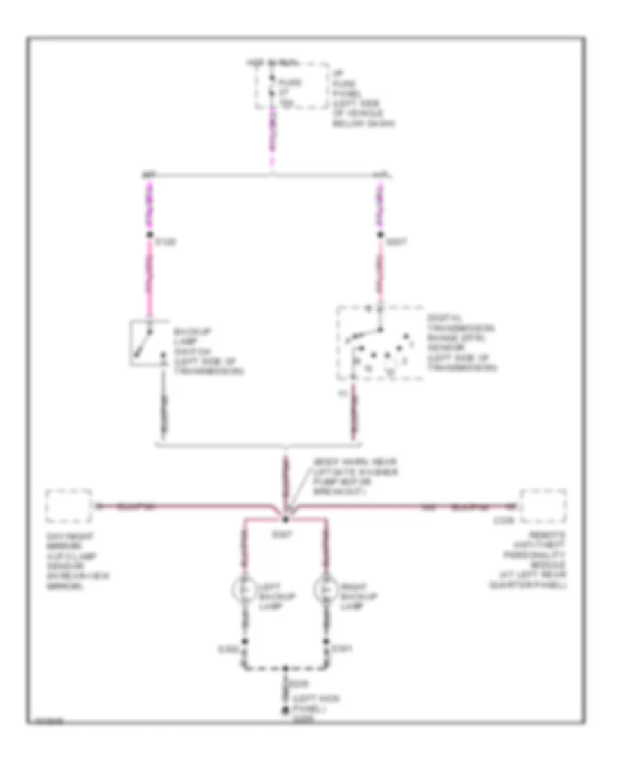
Backup Lamps Wiring Diagram for Ford Explorer 1998
 https://portal-diagnostov.com/license.html
Automotive Electricians Portal FZCO
Automotive Electricians Portal FZCO
https://portal-diagnostov.com/license.html
https://portal-diagnostov.com/license.html
Automotive Electricians Portal FZCO
Automotive Electricians Portal FZCOList of elements for Backup Lamps Wiring Diagram for Ford Explorer 1998:
- (body harn, near liftgate washer pump motor breakout)
- A/t
- Backup lamp switch (left side of transmission)
- C336
- Day/night mirror/ auto lamp sensor (in rear-view mirror)
- Digital transmission range (dtr) sensor (left side of transmission)
- Fuse 15a
- Hot in run
- I/p fuse panel (left side of vehicle below dash)
- Left backup lamp
- M/t
- Panel) g200
- Remote anti-theft personality module (at left rear quarter panel)
- Right backup lamp
- S120
- S207
- S235
- S302
- S307
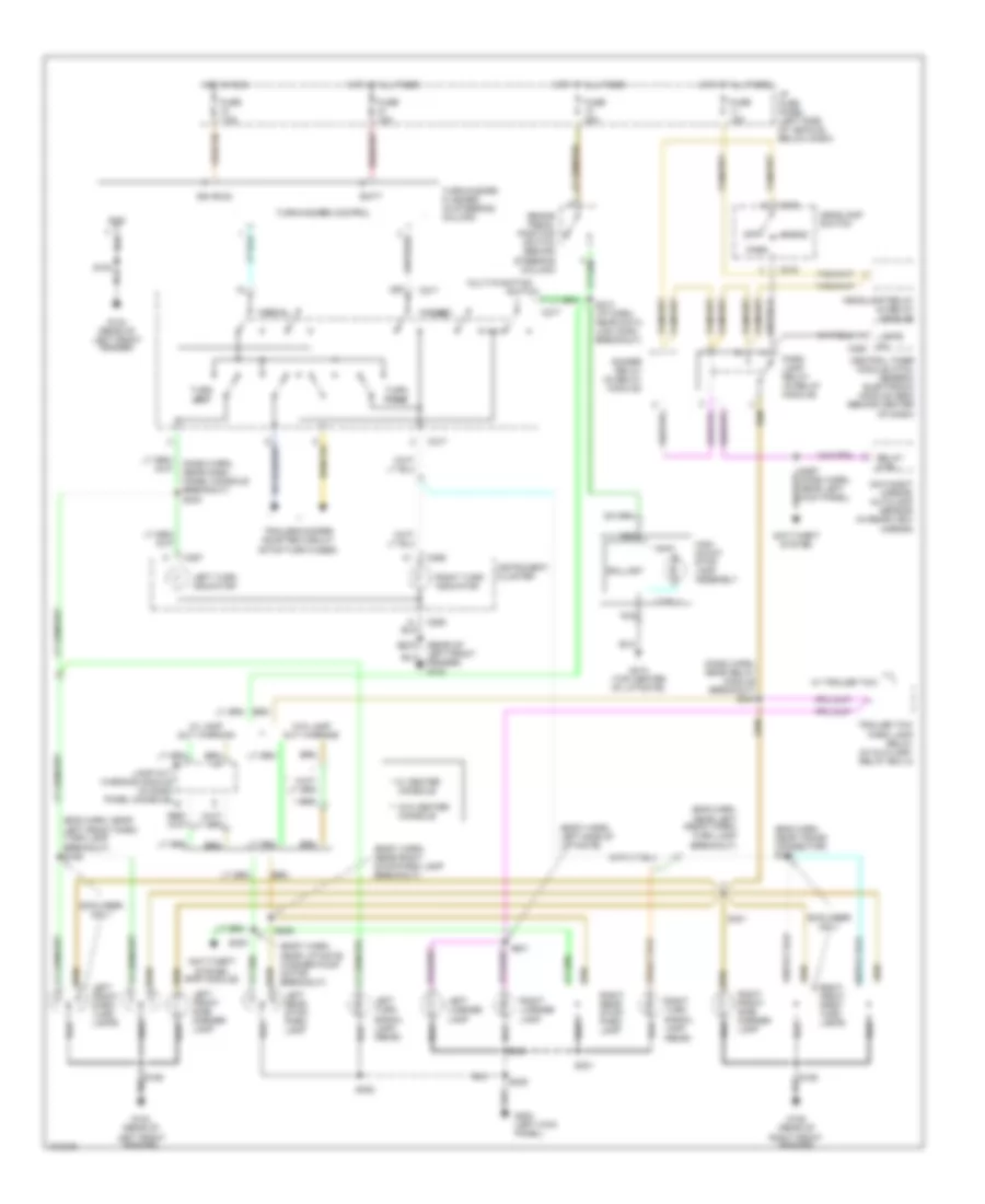
Exterior Lamps Wiring Diagram for Ford Explorer 1998
 https://portal-diagnostov.com/license.html
Automotive Electricians Portal FZCO
Automotive Electricians Portal FZCO
https://portal-diagnostov.com/license.html
https://portal-diagnostov.com/license.html
Automotive Electricians Portal FZCO
Automotive Electricians Portal FZCOList of elements for Exterior Lamps Wiring Diagram for Ford Explorer 1998:
- (body harn, left side of liftgate)
- (body harn, near liftgate washer pump motor breakout)
- (body harn, near right stop/park lamp breakout)
- (dash harn, near dash panel console breakout) s233
- (dash harn, near relay module breakout) s244
- (eng harn, near left front park/ turn lamp breakout)
- (eng harn, near left front park/ turn lamp breakout) s126
- (eng harn, near trans connector) s122
- (rear of left front fender) g104
- (rear)
- * w/ center
- ** w/o center
- Anti-theft system
- Anti-theft system (rap module)
- Ballast
- Batt
- Brake pedal position switch (behind steering column)
- C216
- C217
- C280
- C286
- C287
- Central timer module (ctm)/ generic electronic module (gem) (behind center of dash)
- Console
- Day/night mirror/ autolamp sensor (in rear-view mirror)
- Dimmer relay (in relay module)
- Explorer only
- Fuse 15a
- Fuse 20a
- Fuse 7.5a
- G104 (rear of left front fender)
- G105 (rear of right front fender)
- G200 (left kick panel)
- G412 (top center of liftgate)
- Gnd
- Hazard
- Head
- Headlamp relay (in relay module)
- Headlamp switch
- High mount stop lamp assembly
- Hot at all times
- Hot in run
- I/p fuse panel (left side of vehicle, below dash)
- Ign (run)
- Instrument cluster
- Lamp out warning module (in dash panel console)
- Lamps on
- Left front park/ turn lamps
- Left front side marker lamp
- Left license lamp
- Left rear stop/ park lamp
- Left turn indicator
- Left turn signal lamp (rear)
- Multi-function
- Nca
- Normal
- Off
- Park
- Park lamp relay (in relay module)
- Relay ctrl
- Right front park/ turn lamps
- Right front side marker lamp
- Right license lamp
- Right rear stop/ park lamp
- Right turn indicator
- Right turn signal lamp
- S154
- S155
- S158
- S212 (i/p harn, near data link conn breakout)
- S229
- S235
- S267 (dash harn, near left kick panel)
- S300
- S301
- S302
- S305
- S401
- S404
- Switch
- Trailer tow park lamp relay (in auxiliary relay box 2)
- Trailer/camper adapter circuit (stop/turn fuses)
- Turn left
- Turn right
- Turn/hazard control
- Turn/hazard flasher (in steering column)
- W/ lamp out warning
- W/ trailer tow
- W/o lamp out warning
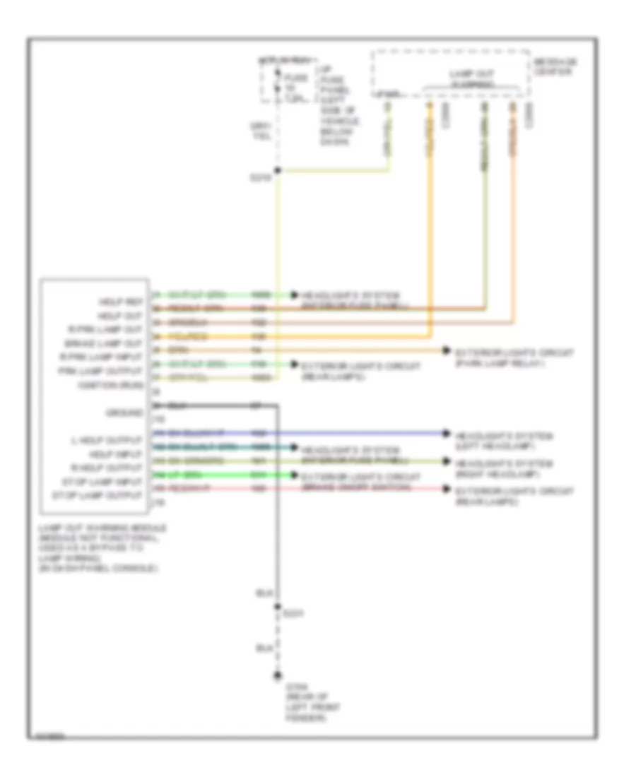
Lamp Outage Module Wiring Diagram for Ford Explorer 1998
 https://portal-diagnostov.com/license.html
Automotive Electricians Portal FZCO
Automotive Electricians Portal FZCO
https://portal-diagnostov.com/license.html
https://portal-diagnostov.com/license.html
Automotive Electricians Portal FZCO
Automotive Electricians Portal FZCOList of elements for Lamp Outage Module Wiring Diagram for Ford Explorer 1998:
- Brake lamp out
- C2008
- C2009
- Exterior lights circuit (brake on/off switch)
- Exterior lights circuit (park lamp relay)
- Exterior lights circuit (rear lamps)
- Fuse 7.5a
- G104 (rear of left front fender)
- Ground
- Hdlp input
- Hdlp out
- Hdlp ref
- Headlights system (interior fuse panel)
- Headlights system (left headlamp)
- Headlights system (right headlamp)
- Hot in run
- I/p fuse panel (left side of vehicle, below dash)
- Ignition (run)
- L hdlp output
- Lamp out warning
- Lamp out warning module (module not functional, used as a bypass to lamp wiring) (in dash panel console)
- Message center
- Prk lamp output
- Pwr
- R hdlp output
- R prk lamp input
- R prk lamp out
- S210
- S231
- Stop lamp input
- Stop lamp output
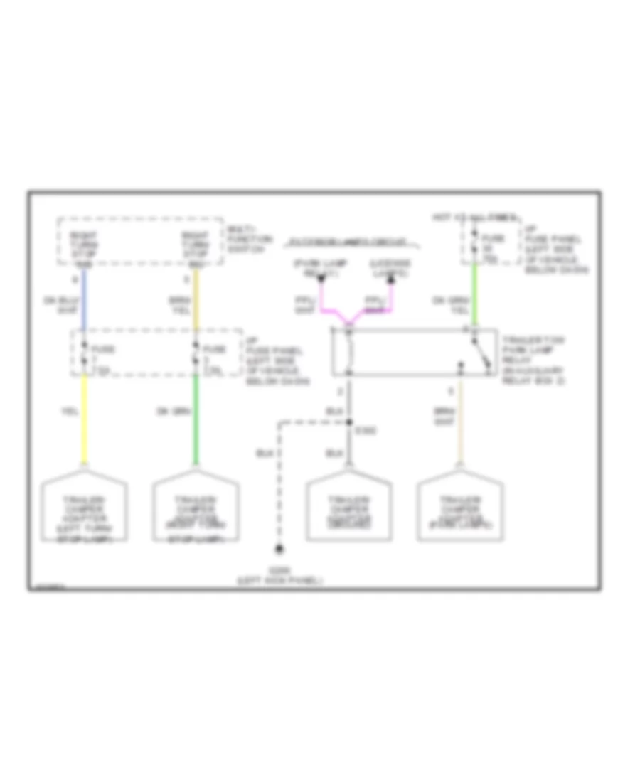
Trailer/Camper Adapter Wiring Diagram for Ford Explorer 1998
 https://portal-diagnostov.com/license.html
Automotive Electricians Portal FZCO
Automotive Electricians Portal FZCO
https://portal-diagnostov.com/license.html
https://portal-diagnostov.com/license.html
Automotive Electricians Portal FZCO
Automotive Electricians Portal FZCOList of elements for Trailer/Camper Adapter Wiring Diagram for Ford Explorer 1998:
- (license lamps)
- (park lamp relay)
- Exterior lamps circuit
- Fuse 15a
- Fuse 7.5a
- G200 (left kick panel)
- Hot at all times
- I/p fuse panel (left side of vehicle, below dash)
- Multi- function switch
- Right turn/ stop sig
- S302
- Stop lamp)
- Trailer tow park lamp relay (in auxiliary relay box 2)
- Trailer/ camper adapter (ground)
- Trailer/ camper adapter (left turn/ stop lamp)
- Trailer/ camper adapter (park lamps)
- Trailer/ camper adapter (right turn/
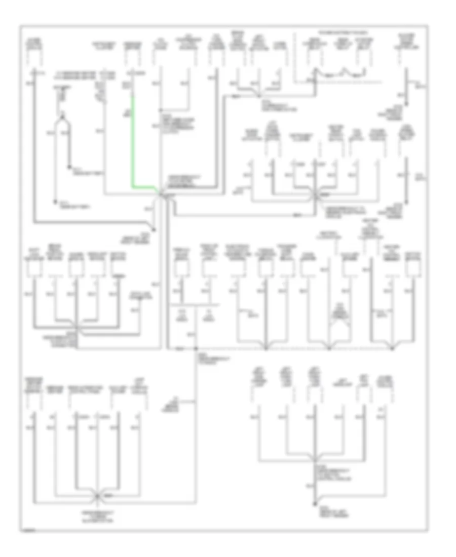
GROUND DISTRIBUTION
Ground Distribution Wiring Diagram (1 of 4) for Ford Explorer 1998
 https://portal-diagnostov.com/license.html
Automotive Electricians Portal FZCO
Automotive Electricians Portal FZCO
https://portal-diagnostov.com/license.html
https://portal-diagnostov.com/license.html
Automotive Electricians Portal FZCO
Automotive Electricians Portal FZCOList of elements for Ground Distribution Wiring Diagram (1 of 4) for Ford Explorer 1998:
- (near breakout to generic electronic module)
- (near breakout to rear blower motor)
- (near breakout to starter motor relay)
- 4wabs control module
- A/c clutch diode
- A/c compressor clutch solenoid
- A/c turn hazard flasher
- Ashtray illumination
- Auxiliary power
- Battery
- Blend door actuator
- Blower motor speed controller
- Brake fluid level warning switch
- Brake pedal position switch
- C118
- C2003
- C2004
- C2009
- C286
- C287
- C288
- Cigar lighter
- Data link connector
- Dimmer module
- Electronic automatic temperature control
- Fog lamp switch
- G104 (rear of left front fender)
- G105 (rear of right front fender)
- G111 (near battery)
- Headlamp switch
- Heated rear window switch
- Heater/ a/c control asembly
- Heater/ a/c control asembly illumination
- High speed blower relay
- Ignition switch
- Instrument cluster
- Lamp out warning module
- Left fog lamp
- Left front park/ turn lamp
- Left front shock actuator
- Left front side marker lamp
- Left headlamp
- Lift gate wiper/ washer switch
- Message center
- Message center switch assembly
- Power antenna module
- Power distribution box
- Premium sound radio
- Radio or front control unit
- Rear integrated control panel
- Rear wiper down relay
- Rear wiper up relay
- S104 (in breakout for wiper motor)
- S154
- S155 (near breakout to ignition control module)
- S200 (near breakout to radio)
- S229
- S230 (near breakout to data link connector)
- S231
- Shift lock actuator
- Starter motor relay
- Torque on demand relay
- Transfer case shift relay
- W/ eatc
- W/ high series console
- W/ lux radio
- W/ message center
- W/0 high series console
- W/o eatc
- W/o lux radio
- W/o message center
- Wiper motor
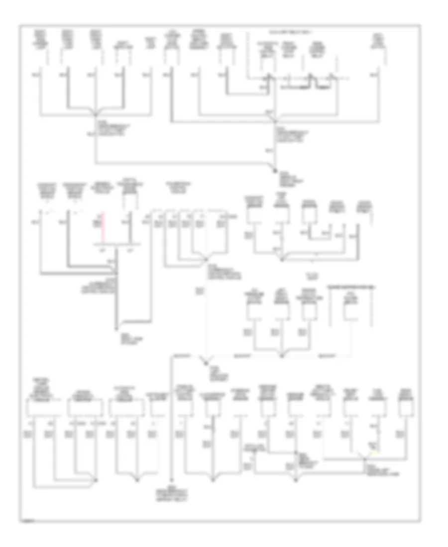
Ground Distribution Wiring Diagram (2 of 4) for Ford Explorer 1998
 https://portal-diagnostov.com/license.html
Automotive Electricians Portal FZCO
Automotive Electricians Portal FZCO
https://portal-diagnostov.com/license.html
https://portal-diagnostov.com/license.html
Automotive Electricians Portal FZCO
Automotive Electricians Portal FZCOList of elements for Ground Distribution Wiring Diagram (2 of 4) for Ford Explorer 1998:
- A/c pressure cutoff switch
- A/t
- Air bag diagnostic monitor
- Anti- theft hood switch
- Automatic ride control module
- Automatic ride control relay
- Auxiliary relay box 1
- C202
- C232
- C233
- Camshaft position sensor
- Camshaft position sensor shield
- Central timer module/ generic electronic module
- Clockspring assembly
- Crankshaft position sensor shield
- Data link connector
- Digital transmission range sensor
- Engine low oil/ temperature switch
- Front washer pump relay
- Fuel tank assembly
- G105 (rear of right front fender)
- G108 (left radiator support)
- G203 (right side of dash)
- Generic electronic module
- Instrument cluster
- Knock sensor
- Knock sensor shield 1
- Knock sensor shield 2
- Left front height sensor
- Low washer fluid level switch
- M/t
- Mass air flow sensor
- Memory seat module
- Message center
- Message center switch assembly
- Passive anti-theft control module
- Pcm power relay
- Power distribution box
- Powertrain control module
- Rear height sensor
- Rear washer control relay
- Remote anti-theft personality module
- Right fog lamp
- Right front park/ turn lamp
- Right front shock actuator
- Right front side marker lamp
- Right headlamp
- S105 (in breakout for powertrain control module)
- S108 (in breakout for powertrain control module)
- S161 (near breakout to anti-theft hood switch)
- S223 (near breakout to g200)
- S232 (near breakout to rear window defrost relay)
- S234 (inside left rear door jamb)
- Speed control servo/ amplifier assembly
- Steering rate sensor
- W/ 4.0l sohc
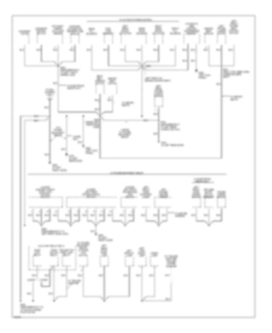
Ground Distribution Wiring Diagram (3 of 4) for Ford Explorer 1998
 https://portal-diagnostov.com/license.html
Automotive Electricians Portal FZCO
Automotive Electricians Portal FZCO
https://portal-diagnostov.com/license.html
https://portal-diagnostov.com/license.html
Automotive Electricians Portal FZCO
Automotive Electricians Portal FZCOList of elements for Ground Distribution Wiring Diagram (3 of 4) for Ford Explorer 1998:
- (2 door) left front power door lock switch
- (2 door) left front power window switch
- (4 door) master window door lock control switch
- (left front of engine compartment)
- (w/ power equipment group) liftgate lock switch
- (w/ trailer adapter) trailer/ camper adapter
- 2 door
- 4 door
- 4 door only
- 4 door w/ power equipment group
- Automatic ride control compressor assembly
- Auxiliary relay box 2
- Cargo lamp
- Compass/ outside air temperature module
- Day/night mirror autolamp sensor
- Door lock relay
- Door unlock relay
- Front fill solenoid
- Fuel tank assembly
- G200 (left kick panel)
- G500 (in left front door)
- G700 (in left rear door)
- Keyless entry switch assembly
- Left backup lamp
- Left front door courtesy lamp
- Left front door disarm switch
- Left front power seat control switch
- Left power lumbar motor
- Left power/ heated mirror
- Left rear power window switch
- Left rear shock actuator
- Left rear stop/ park lamp
- Left turn signal lamp
- Memory seat module
- Memory seat switch
- Moonroof control switch
- Moonroof motor
- Power mirror switch
- Rear fill solenoid
- Rear gate solenoid
- Right rear shock actuator
- S202 (near breakout to left vanity mirror lamp)
- S235 (inside left rear door jamb)
- S302 (near breakout to liftgate washer pump motor)
- S321 (seat ctrl feed harn, under driver's seat)
- S351
- S500 (near breakout to left front door lock)
- S700 (near breakout to left rear window switch)
- Seat belt warning switch
- To s301 (diagram 4 of 4)
- Trailer tow park lamp relay
- W/ automatic ride control
- W/ electronic group only
- W/ heated mirrors
- W/ memory seats
- W/ power equipment group
- W/ trailer adapter
- W/o power equipment group
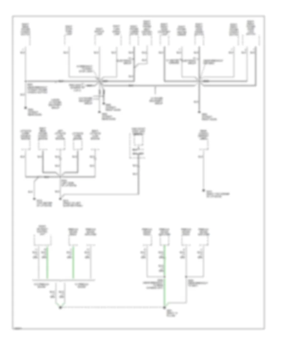
Ground Distribution Wiring Diagram (4 of 4) for Ford Explorer 1998
 https://portal-diagnostov.com/license.html
Automotive Electricians Portal FZCO
Automotive Electricians Portal FZCO
https://portal-diagnostov.com/license.html
https://portal-diagnostov.com/license.html
Automotive Electricians Portal FZCO
Automotive Electricians Portal FZCOList of elements for Ground Distribution Wiring Diagram (4 of 4) for Ford Explorer 1998:
- (in breakout to right stop lamp)
- (near breakout for g600)
- 4 door w/ power equipment group
- Ballast
- From s235 (diagram 3 of 4)
- G410 (right top corner of liftgate)
- G412 (top center of liftgate)
- G414 (front of left quarter panel)
- G600 (in right front door)
- G800 (in right rear door)
- G901 (right "a" pillar)
- High mount stop lamp assembly
- Left liftgate ajar switch
- Liftgate wiper disable switch
- Liftgate wiper motor
- Premium sound amplifier
- Premium sound radio
- Radio or front control unit
- Rear window defrost grid
- Right backup lamp
- Right front door courtesy lamp
- Right front door disarm switch
- Right front power door lock switch
- Right front power seat control switch
- Right front power window switch
- Right liftgate ajar switch
- Right power lumbar motor
- Right power/ heated mirror
- Right rear power window switch
- Right stop/ park lamp
- Right turn signal lamp
- S205 (near breakout to g201)
- S301
- S352 (near breakout to rear chassis unit)
- S404 (left side of liftgate)
- S602
- S800 (near breakout to right power window switch)
- W/ electronic group
- W/ heated mirrors
- W/ power equipment group
- W/ premium sound
- W/o power equipment group
- W/o premium sound
HEADLIGHTS
Autolamps Wiring Diagram for Ford Explorer 1998
 https://portal-diagnostov.com/license.html
Automotive Electricians Portal FZCO
Automotive Electricians Portal FZCO
https://portal-diagnostov.com/license.html
https://portal-diagnostov.com/license.html
Automotive Electricians Portal FZCO
Automotive Electricians Portal FZCOList of elements for Autolamps Wiring Diagram for Ford Explorer 1998:
- (eng compt harn, near left front of eng compt)
- (eng compt harn, near left headlamp breakout) s112
- (i/p harn, near left kick panel) s267
- C210
- C280
- C287
- C338
- Day/night mirror/ autolamp sensor (mounted in rear view mirror)
- Day/nt mir out
- Dimmer relay
- Dimmer switch
- Exterior lights system
- Flash-to- pass switch
- Fuse 10a
- Fuse 15a
- Fuse 30a
- Fuse 7.5a
- G104 (rear of left front fender)
- G105 (rear of right front fender)
- G200 (left kick panel)
- Generic electronic module (gem) (behind center of dash)
- Ground
- Head
- Headlamp relay
- Headlamp switch
- Headlamps circuit (w/ drl) (daytime running lamps module pin 6)
- Headlamps circuit (w/ drl) (daytime running lamps module pin 8)
- Headlamps/ fog lamps circuit
- Hi beam indicator
- Hot at all times
- Hot in start or run
- I/p fuse panel
- Ignition
- Instrument cluster
- Lamp out warning module (in dash panel console)
- Left headlamp
- Memory system (memory seats)
- Mirrors system (automatic day/night miror)
- Multi- function switch
- Off
- Park
- Park lamp relay
- Pass
- Power
- Power distribution box
- Relay module (behind center of dash)
- Relay output
- Remote anti-theft personality (rap) module (at left rear quarter panel)
- Right headlamp
- S103
- S111
- S155
- S202
- S209
- S213
- S229
- S237
- S266 (i/p harn, near headlamp switch breakout)
- W/ drl
- W/ lamp out warning
- W/ memory seat
- W/o drl
- W/o lamp out warning
- W/o memory seat
Headlamps/Fog Lamps Wiring Diagram, with DRL for Ford Explorer 1998
 https://portal-diagnostov.com/license.html
Automotive Electricians Portal FZCO
Automotive Electricians Portal FZCO
https://portal-diagnostov.com/license.html
https://portal-diagnostov.com/license.html
Automotive Electricians Portal FZCO
Automotive Electricians Portal FZCOList of elements for Headlamps/Fog Lamps Wiring Diagram, with DRL for Ford Explorer 1998:
- (eng compt harn, near left front of eng compt) s111
- (eng compt harness, nearleft headlamp breakout) s112
- Acc
- Battery
- Brake fluid level warning switch (mounted on left side of master cylinder)
- Brake indicator
- Breakout)
- C210
- C216
- C287
- C288
- Daytime running lamps (drl) module (left front corner of engine compt)
- Dimmer switch
- Drl disable
- Flash-to- pass switch
- Fuse 11 7.5a
- Fuse 12 30a
- Fuse 27 10a
- Fuse 33 15a
- Fuse 4 10a
- Fuse 4 15a
- Fuse 8 10a
- G104 (rear of left fender apron)
- G105 (rear of right fender apron)
- Head
- Headlamp switch
- Headlamps
- Headlamps circuit (w/ autolamps)
- Headlamps/ fog lamps circuit (fog lamp relay)
- Hi beam ind feed
- Hi beam indicator
- Hot at all times
- Hot in run
- Hot in run or start
- Ign feed
- Ignition switch
- Instrument cluster
- Interior fuse panel
- Lamp out warning module (in dash panel console)
- Left headlamp
- Lock
- Low
- Multi- function switch
- Normal
- Off
- Park
- Parking brake switch (on right side of parking brake lever)
- Pass
- Power distribution box
- Right headlamp
- Run
- S103
- S153
- S155
- S176 (eng compt harn, near brake press switch breakout)
- S207
- S213
- S229
- S237
- Start
- W/ lamp out warning
- W/o lamp out warning
Headlamps/Fog Lamps Wiring Diagram, without DRL for Ford Explorer 1998
 https://portal-diagnostov.com/license.html
Automotive Electricians Portal FZCO
Automotive Electricians Portal FZCO
https://portal-diagnostov.com/license.html
https://portal-diagnostov.com/license.html
Automotive Electricians Portal FZCO
Automotive Electricians Portal FZCOList of elements for Headlamps/Fog Lamps Wiring Diagram, without DRL for Ford Explorer 1998:
- (eng compt harn, near left front of eng compt) s111
- (eng compt harn, near left front of eng compt) s172
- (i/p harn, near headlamp switch breakout)
- C210
- C216
- C287
- Dimmer switch
- Flash-to- pass
- Fog lamp relay
- Fog lamp switch
- Fuse 15a
- Fuse 30a
- Fuse 33 15a
- Fuse 4 10a
- Fuse 8 10a
- G104 (rear of left fender apron)
- G105 (rear of right fender apron)
- Head
- Headlamp switch
- Hi beam indicator
- Hot at all times
- Illum
- Instrument cluster
- Interior fuse panel
- Interior lights system
- Lamp out warning module (in dash panel console)
- Left fog lamp
- Left headlamp
- Multi- function switch
- Off
- Park
- Pass
- Power distribution box
- Relay box no1
- Right fog lamp
- Right headlamp
- S103
- S112 (eng compt harn, near left headlamp breakout)
- S115
- S155
- S158
- S229
- S237
- S266
- W/ fog lamps only
- W/ lamp out warning
- W/o lamp out warning
HORN
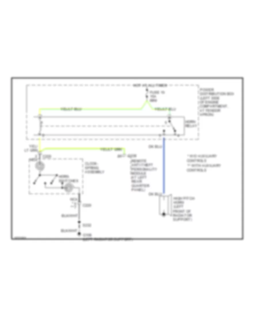
Horn Wiring Diagram for Ford Explorer 1998
 https://portal-diagnostov.com/license.html
Automotive Electricians Portal FZCO
Automotive Electricians Portal FZCO
https://portal-diagnostov.com/license.html
https://portal-diagnostov.com/license.html
Automotive Electricians Portal FZCO
Automotive Electricians Portal FZCOList of elements for Horn Wiring Diagram for Ford Explorer 1998:
- * w/o auxiliary
- ** with auxiliary
- C220
- C338
- Clock- spring assembly
- Controls
- Front of radiator support)
- Fuse 10 15a mini
- G108 (left radiator support)
- High pitch horn (left
- Horn relay
- Horn switches
- Hot at all times
- Nca
- Power distribution box (left side of engine compartment, at fendor apron)
- Remote anti-theft personality module (at left rear quarter panel)
- S232
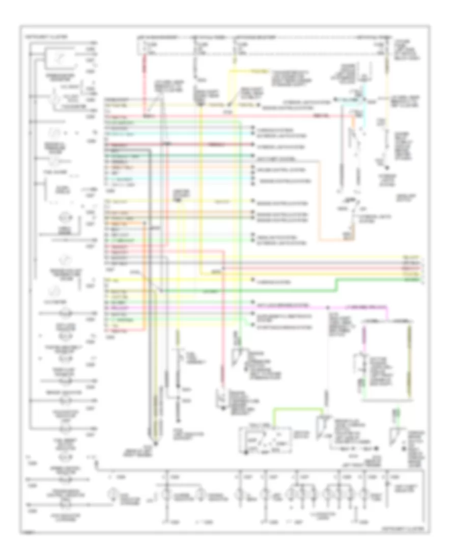
INSTRUMENT CLUSTER
Instrument Cluster Wiring Diagram (1 of 2) for Ford Explorer 1998
 https://portal-diagnostov.com/license.html
Automotive Electricians Portal FZCO
Automotive Electricians Portal FZCO
https://portal-diagnostov.com/license.html
https://portal-diagnostov.com/license.html
Automotive Electricians Portal FZCO
Automotive Electricians Portal FZCOList of elements for Instrument Cluster Wiring Diagram (1 of 2) for Ford Explorer 1998:
- "anti-theft" indicator
- "brake" indicator
- "door ajar" indicator
- "fasten seatbelt" indicator
- (4.0l ohv & 5.0l)
- (4.ol sohc)
- (center of dash) s274
- (eng compt harn, near a/c relay)
- (eng compt harn, near gem) s275
- (i/p harn, near breakout to inst cluster)
- 4.0l ohv & 5.0l
- 4.0l sohc
- 4wd indicator (hi-range)
- 4wd indicator (lo-range)
- Acc
- Air bag indicator
- Anti-lock brakes system
- Anti-lock indicator
- Anti-theft system
- Brake fluid level warning switch (mounted on low left side of master cylinder)
- C286
- C287
- C288
- Charge indicator
- Check gauge
- Cruise control system
- Daytime running lamps (drl) module (left front corner of eng compt)
- Dc out
- Dimmer module (left side of steering column)
- Dimmer relay (in relay module, behind center of dash)
- Engine controls system
- Engine coolant temperature gauge
- Engine coolant temperature sender (behind gen bracket)
- Engine oil pressure gauge
- Engine oil pressure switch (on engine, next to power steering pump)
- Exterior lights system
- Fuel guage
- Fuel reset switch indicator
- Fuel tank assembly
- Fuse 15a
- Fuse 7.5a
- G104 (rear of left front fender)
- G108 (left radiator support)
- Head
- Headlamp switch
- Headlights system
- Hi beam
- Hot at all times
- Hot in run or start
- I/p fuse panel (left side of vehicle, below dash)
- Ignition switch
- Illumination lamps
- Instrument cluster
- Interior lights system
- Left turn
- Lock
- Malfunction indicator lamp
- Off
- Park
- Parking brake switch (on right side of parking brake lever)
- Right turn
- Run
- S104
- S128
- S154
- S176 (eng compt harn, near breakout to brk press switch)
- S213
- S228
- S229
- S232
- S234
- S242
- S264
- S276
- Slosh module
- Speed control indicator
- Speedometer/ odometer
- Start
- Starting/charging system
- Tachometer
- Tachometer data link connector (right rear corner of engine compt)
- Transmission control indicator (tcil)
- Voltmeter
- W/ drl
- W/o drl
- Warning system
- Warning systems
Instrument Cluster Wiring Diagram (2 of 2) for Ford Explorer 1998
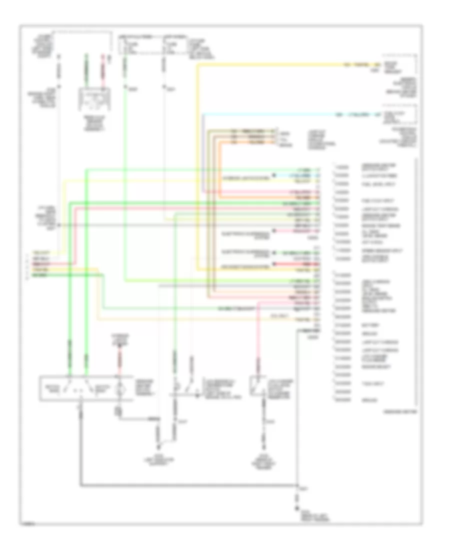 https://portal-diagnostov.com/license.html
Automotive Electricians Portal FZCO
Automotive Electricians Portal FZCO
https://portal-diagnostov.com/license.html
https://portal-diagnostov.com/license.html
Automotive Electricians Portal FZCO
Automotive Electricians Portal FZCOList of elements for Instrument Cluster Wiring Diagram (2 of 2) for Ford Explorer 1998:
- (arc) disable switch input
- (arc) warning input oil temp/ level sense english/metric output (gem) to message center
- (i/p harn, near breakout to instr cluster) s247
- 1/c2008
- 10/c2008
- 11/c2008
- 12/c2008
- 2/c2008
- 21/c2009
- 22/c2009
- 23/c2009
- 24/c2009
- 25/c2009
- 26/c2009
- 27/c2009
- 28/c2009
- 29/c2009
- 3/c2008
- 30/c2009
- 31/c2009
- 32/c2009
- 33/c2009
- 34/c2009
- 35/c2009
- 36/c2009
- 4/c2008
- 4wabs control module (left side of engine compt)
- 5.0l only
- 5/c2008
- 6/c2008
- 7/c2008
- 8/c2008
- 9/c2008
- Air conditioning system
- Battery
- Brake
- C186
- C2008
- C2009
- C280
- Electronic suspension system
- Engine select
- Engine temp sense
- Fuel flow input
- Fuel flow rate output
- Fuel level input
- Fuse 7.5a
- G104 (rear of left front fender)
- G105 (rear of right front fender)
- G108 (left radiator support)
- Generic electronic module (behind center of dash)
- Ground
- Head
- Hot at all times
- Hot in run
- I/p fuse panel (left side of vehicle, below dash)
- Illumination feed
- Interior lights system
- Lamp out warning
- Lamp out warning module (in dash panel console)
- Low engine oil/ temperature switch (left side of engine, on oil pan)
- Low washer fluid level switch (in washer reservoir)
- Low washer fluid sense
- Message center
- Message center switch assembly
- Message center switch input
- Oil temp/ level sense
- Powertrain control module (mounted through firewall)
- Rear axle sensor (on axle assembly)
- Red
- Red/pnk
- S137
- S161
- S168 (engine compt harn, near 4wabs ctrl module)
- S209
- S231
- S233
- S241
- Sound tone request
- Speed sensor input
- Switch bank
- Tach input
- Tail
Overhead Console Wiring Diagram for Ford Explorer 1998
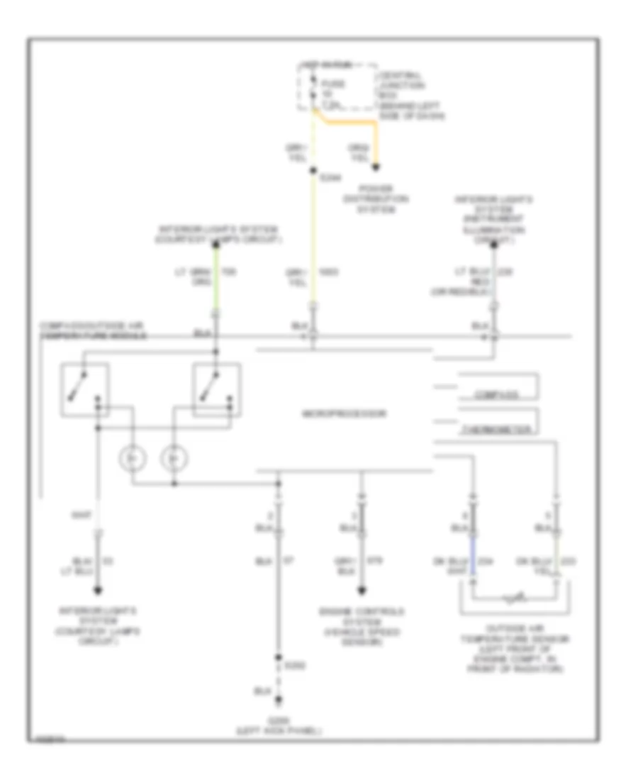 https://portal-diagnostov.com/license.html
Automotive Electricians Portal FZCO
Automotive Electricians Portal FZCO
https://portal-diagnostov.com/license.html
https://portal-diagnostov.com/license.html
Automotive Electricians Portal FZCO
Automotive Electricians Portal FZCOList of elements for Overhead Console Wiring Diagram for Ford Explorer 1998:
- Central junction box (behind left side of dash)
- Compass
- Compass/outside air temperature module
- Engine controls system (vehicle speed sensor)
- Fuse 7.5a
- G200 (left kick panel)
- Hot in run
- Interior lights system (courtesy lamps circuit)
- Interior lights system (instrument illumination circuit)
- Microprocessor
- Outside air temperature sensor (left front of engine compt, in front of radiator)
- Power distribution system
- S202
- S244
- Thermometer
INTERIOR LIGHTS
Courtesy Lamps Wiring Diagram for Ford Explorer 1998
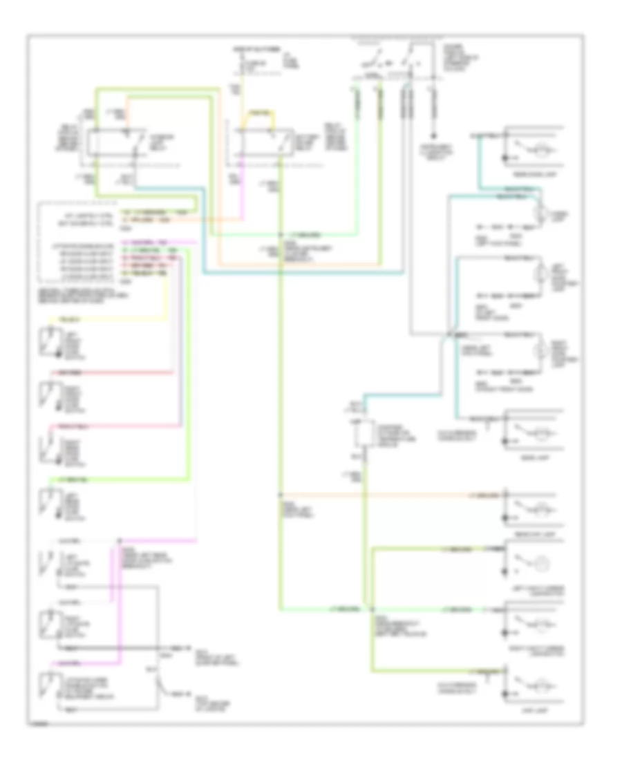 https://portal-diagnostov.com/license.html
Automotive Electricians Portal FZCO
Automotive Electricians Portal FZCO
https://portal-diagnostov.com/license.html
https://portal-diagnostov.com/license.html
Automotive Electricians Portal FZCO
Automotive Electricians Portal FZCOList of elements for Courtesy Lamps Wiring Diagram for Ford Explorer 1998:
- (near left kick panel)
- Bat saver rly ctrl
- Battery saver relay
- C280
- C283
- Cargo lamp
- Central timer module (ctm)/ generic electronic module (gem) (behind center of dash)
- Cluster breakout)
- Compass/ outside air temperature module
- Dimmer module (left side of steering column)
- Dome lamp
- Fuse 26 10a
- G200 (left kick panel)
- G412 (top center of lifgate)
- G414 (front of left quarter panel)
- G500 (in left front door)
- G600 (in right front door)
- Hot at all times
- I/p fuse panel
- Instrument illumination circuit
- Int lamp rly ctrl
- Interior lamp relay
- Left front door ajar switch
- Left front door courtesy lamp
- Left liftgate ajar switch
- Left rear door ajar switch
- Left vanity mirror lamp/switch
- Lf door ajar input
- Liftgate disable/ajar
- Liftgate wiper disable switch (w/ power equipment group)
- Lr door ajar input
- Map lamp
- Nca
- Norm
- Off
- Rear dome lamp
- Rear map lamp
- Relay module (behind center of dash)
- Rf door ajar input
- Right front door ajar switch
- Right front door courtesy lamp
- Right liftgate ajar switch
- Right rear door ajar switch
- Right vanity mirror lamp/switch
- Rr door ajar input
- S203
- S234 (near breakout to driver's seat belt buckle)
- S302
- S322 (near left kick panel)
- S404
- S409 (near left rear door ajar switch breakout)
- S500
- S602
- W/o overhead console only
Instrument Illumination Wiring Diagram (1 of 2) for Ford Explorer 1998
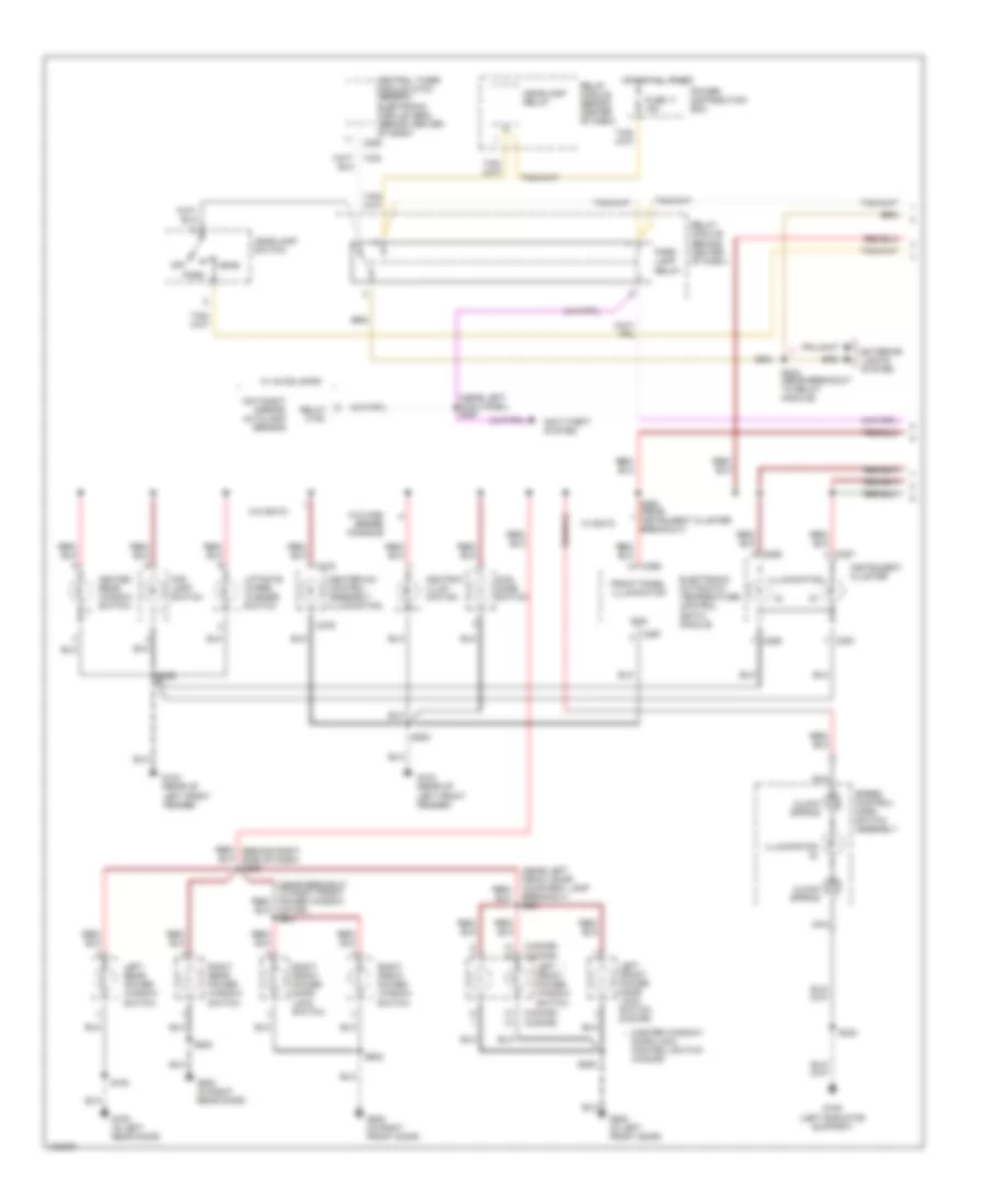 https://portal-diagnostov.com/license.html
Automotive Electricians Portal FZCO
Automotive Electricians Portal FZCO
https://portal-diagnostov.com/license.html
https://portal-diagnostov.com/license.html
Automotive Electricians Portal FZCO
Automotive Electricians Portal FZCOList of elements for Instrument Illumination Wiring Diagram (1 of 2) for Ford Explorer 1998:
- (2-door) (4-door)
- (3)
- (4-door) (2-door)
- (near left front door courtesy lamp breakout) s501
- (near left kick panel) s267
- 4wd mode switch
- Anti-theft system
- Ashtray illum- ination
- C276
- C280
- C286
- C287
- C297
- C298
- Central timer module (ctm)/ generic electronic module (gem) (behind center of dash)
- Clock spring
- Day/night mirror/ autolamp sensor
- Electronic automatic temperature control (eatc) module
- Exterior lights system
- Fog lamp switch
- Front panel illumination
- Fuse 11 15a
- G104 (rear of
- G108 (left radiator support)
- G500 (in left front door)
- G700 (in left rear door)
- G800 (in right front door)
- G800 (in right rear door)
- Gnd
- Head
- Headlamp relay
- Headlamp switch
- Heated rear window switch
- Heater-a/c control assembly illumination
- Hot at all times
- Illumination
- Illumination (2)
- Instrument cluster
- Left front fender)
- Left front power door lock switch (2-door)
- Left front power window switch
- Left rear power window switch
- Liftgate wiper/ washer switch
- Master window/ * door lock control switch (4-door)
- Motor) s601
- Nca
- Off
- Park
- Park lamp relay
- Power distribution box
- Red/ (behind right side of dash) s306
- Relay ctrl
- Relay module (behind center of dash)
- Right front power door lock switch
- Right front power window switch
- Right rear power window switch
- S200
- S229
- S232
- S244 (near breakout to relay module)
- S264 (near instrument cluster breakout)
- S500
- S602
- S700
- S800
- Speed control/ horn switch assembly
- W/ autolamps
- W/ eatc
- W/o eatc
- W/o high series console
Instrument Illumination Wiring Diagram (2 of 2) for Ford Explorer 1998
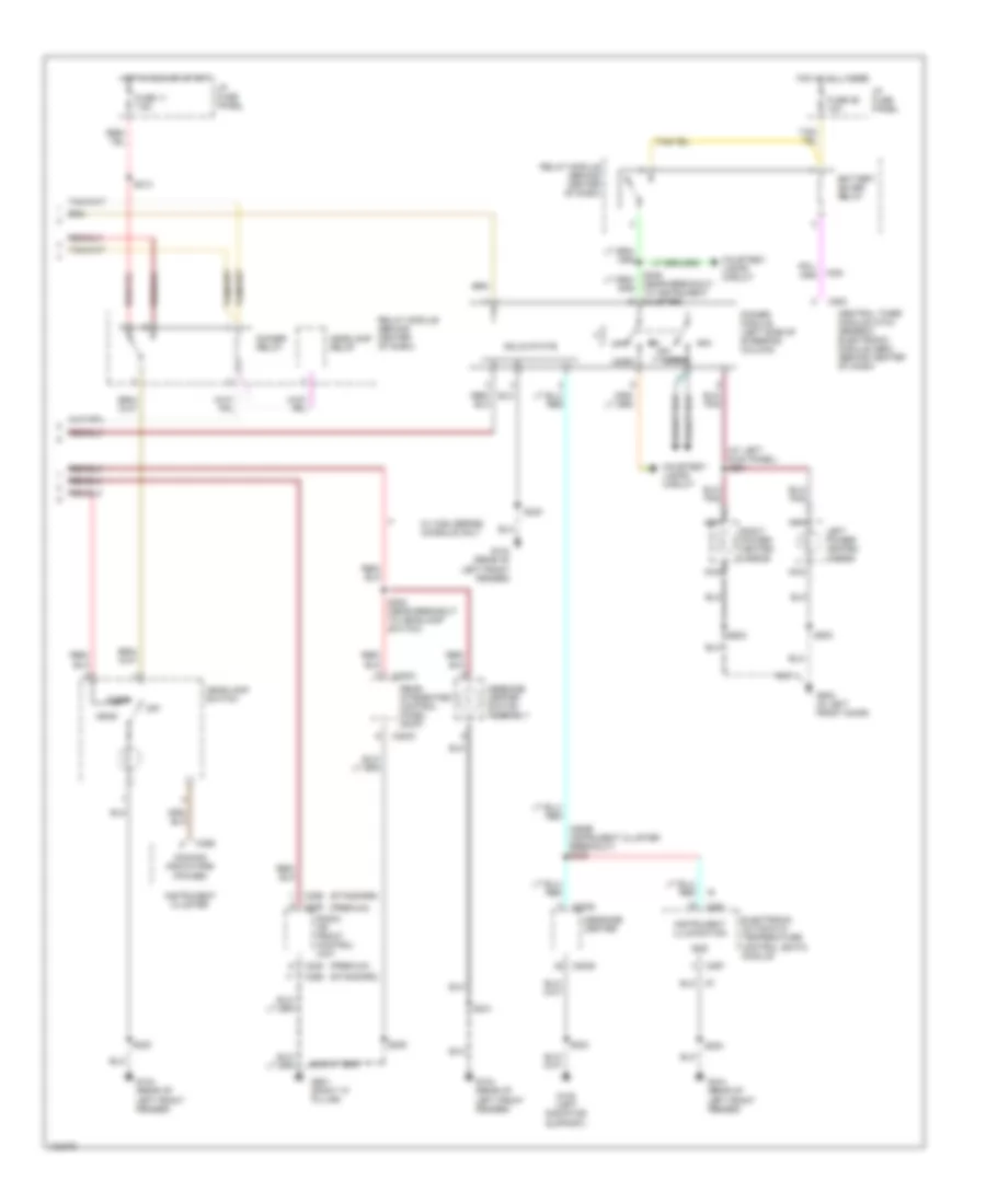 https://portal-diagnostov.com/license.html
Automotive Electricians Portal FZCO
Automotive Electricians Portal FZCO
https://portal-diagnostov.com/license.html
https://portal-diagnostov.com/license.html
Automotive Electricians Portal FZCO
Automotive Electricians Portal FZCOList of elements for Instrument Illumination Wiring Diagram (2 of 2) for Ford Explorer 1998:
- (at left kick panel) s261
- (near instrument cluster breakout) s228
- (premium)
- (standard)
- Battery saver relay
- C2003
- C2008
- C2009
- C228
- C256
- C283
- C286
- C297
- Central timer module (ctm)/ generic electronic module (gem) (behind center of dash)
- Courtesy lamps circuit
- Dimmer module (left side of steering column)
- Dimmer relay
- Dimming indicators (power)
- Electronic automatic temperature control (eatc) module
- Fuse 11 7.5a
- Fuse 26 10a
- G104 (rear of
- G108 (left radiator support)
- G500 (in left front door)
- G901 (right "a" pillar)
- Gnd
- Head
- Headlamp relay
- Headlamp switch
- Hot at all times
- Hot in run or start
- I/p fuse panel
- Instrument cluster
- Instrument illumination
- Left front fender)
- Left power/ heated mirror
- Message center
- Message center switch assembly
- Nca
- Norm
- Off
- Park
- Radio or front control unit
- Rear integrated control panel (ricp)
- Relay module (behind center of dash)
- Right power/ heated mirror
- S200
- S205
- S208 (near breakout to headlamp switch)
- S213
- S223
- S230
- S231
- S500
- S602
- Solid state
- W/ high series console only
MEMORY SYSTEMS
Memory System Wiring Diagrams for Ford Explorer 1998
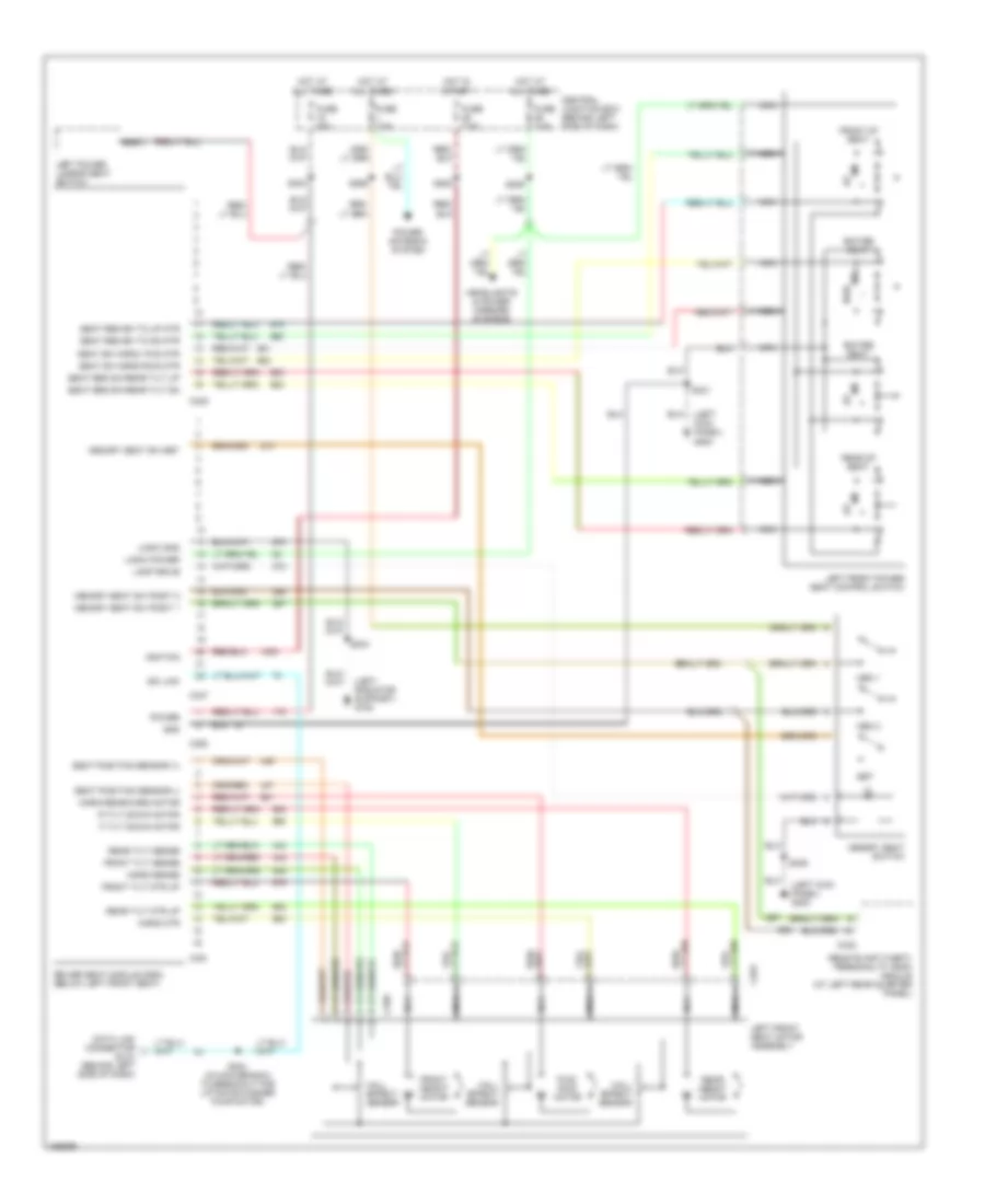 https://portal-diagnostov.com/license.html
Automotive Electricians Portal FZCO
Automotive Electricians Portal FZCO
https://portal-diagnostov.com/license.html
https://portal-diagnostov.com/license.html
Automotive Electricians Portal FZCO
Automotive Electricians Portal FZCOList of elements for Memory System Wiring Diagrams for Ford Explorer 1998:
- (left kick panel) g200
- (left radiator support) g108
- C335
- C337
- C338
- C350
- C351
- C353
- C359
- Central junction box (behind left side of dash)
- Data link connector (dlc) (behind left side of dash)
- Driver seat module (dsm) (below left front seat)
- Entire seat
- F tilt down motor
- Front height motor
- Front of seat
- Front tilt mtr up
- Front tilt sense
- Fuse 25a
- Fuse 7.5a
- Fwd
- Fwd/ rwd motor
- Gnd
- Hall effect sensor
- Headlights & power mirrors systems
- Horiz mtr
- Horiz rearward motor
- Horiz sense
- Hot at all times
- Hot in start
- Ignition
- Iso link
- Lamp drive
- Left front power seat control switch
- Left front seat motor assembly
- Left power lumbar seat switch
- Logic gnd
- Logic power
- Mem 1
- Mem 2
- Memory seat sw posit 1
- Memory seat sw posit 2
- Memory seat sw set
- Memory seat switch
- Nca
- Power
- Power antenna system
- R tilt down motor
- Rear height motor
- Rear of seat
- Rear tilt mtr up
- Rear tilt sense
- Remote anti-theft/ personality (rap) module (at left rear quarter panel)
- Rwd
- S209
- S234
- S235
- S265
- S282
- S303
- S304 (in main branch to breakout for liftgate washer pump motor)
- S321
- Seat position sensor (+)
- Seat position sensor (-)
- Seat reg sw rear tilt dn
- Seat reg sw rear tilt up
- Seat reg sw to dn mtr
- Seat reg sw to up mtr
- Seat sw horiz rwd mtr
- Seat sw horiz. fwd mtr
- Set
POWER ANTENNA
Power Antenna Wiring Diagram for Ford Explorer 1998
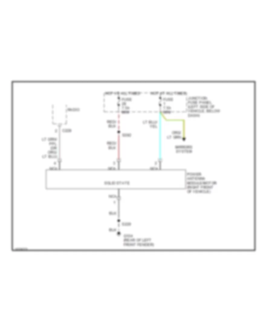 https://portal-diagnostov.com/license.html
Automotive Electricians Portal FZCO
Automotive Electricians Portal FZCO
https://portal-diagnostov.com/license.html
https://portal-diagnostov.com/license.html
Automotive Electricians Portal FZCO
Automotive Electricians Portal FZCOList of elements for Power Antenna Wiring Diagram for Ford Explorer 1998:
- C228
- Fuse 7.5a mini
- G104 (rear of left front fender)
- Hot at all times
- Junction fuse panel (left side of vehicle, below dash)
- Mirrors system
- Nca
- Power antenna module/motor (right front of vehicle)
- Radio
- S229
- S282
- Solid state
POWER DISTRIBUTION
Power Distribution Wiring Diagram (1 of 4) for Ford Explorer 1998
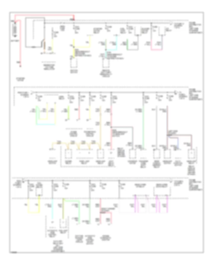 https://portal-diagnostov.com/license.html
Automotive Electricians Portal FZCO
Automotive Electricians Portal FZCO
https://portal-diagnostov.com/license.html
https://portal-diagnostov.com/license.html
Automotive Electricians Portal FZCO
Automotive Electricians Portal FZCOList of elements for Power Distribution Wiring Diagram (1 of 4) for Ford Explorer 1998:
- (left side of dash) s237
- (right corner of dash) s239
- 4wabs control module
- A/c relay
- Accy delay relay
- Air bag diagnostic monitor
- Automatic ride control on/off switch
- Automatic ride control relay
- Auxiliary relay box no 1 (left side of engine compartment)
- Battery
- Blower motor relay
- Daytime running lamps module
- Dimmer relay
- Fog lamp relay
- From b fuse 3 (diagram 1 of 4)
- From fuse 1 (diagram 1 of 4)
- Fuel pump relay
- Fuse 10a
- Fuse 15a
- Fuse 20a
- Fuse 30a
- Generator/ voltage regulator
- Headlamp relay
- Headlamp switch
- Horn relay
- Ignition switch
- Maxi fuse 20a
- Maxi fuse 30a
- Maxi fuse 40a
- Maxi fuse 50a
- Mega fuse 175a
- Moonroof motor
- Multi- function switch
- Nca
- Park lamp relay
- Pcm power relay
- Power distribution box (left side of engine compartment)
- Powertrain control module
- Rear window defrost relay
- Rear wiper down relay
- Rear wiper up relay
- Red
- Relay module (behind center of dash)
- Remote anti-theft personality module
- S160 (near breakout to power distribution box)
- S236 (near breakout to headlamp switch)
- Starter motor
- Starter motor relay
- To fuse 10 (diagram 1 of 4)
- To fuse 5 (diagram 2 of 4)
- To fuse 8 (diagram 1 of 4)
- Transfer case shift relay
Power Distribution Wiring Diagram (2 of 4) for Ford Explorer 1998
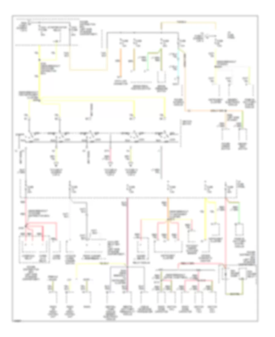 https://portal-diagnostov.com/license.html
Automotive Electricians Portal FZCO
Automotive Electricians Portal FZCO
https://portal-diagnostov.com/license.html
https://portal-diagnostov.com/license.html
Automotive Electricians Portal FZCO
Automotive Electricians Portal FZCOList of elements for Power Distribution Wiring Diagram (2 of 4) for Ford Explorer 1998:
- (near breakout for instrument cluster) s209
- (near breakout to fuel injector 3)
- (near breakout to instrument cluster) s213
- (near breakout to power distribution box)
- (near breakout to radio) s242
- (not used)
- 4.0l
- 5.0l
- Acc
- Air bag diagnostic monitor
- Am/fm
- Auxiliary relay box no 1 (left side of engine compartment)
- Brake pedal position switch
- Brake pressure switch
- Central timer module/ generic electronic module
- Data link connector
- Day/night mirror/ autolamp sensor
- Dimmer relay
- From c fuse 8 (diagram 1 of 4)
- Front washer pump relay
- Fuse 10a
- Fuse 20a
- Fuse 25a
- Fuse 30a
- Fuse 7.5a
- Generic electronic module
- I/p fuse panel
- Ignition coil
- Ignition coil 1 & 2
- Ignition coil 3 & 4
- Ignition switch
- Instrument cluster
- Liftgate wiper/ washer switch
- Lock
- Lux
- Maxi fuse 50a
- Maxi fuse 60a
- Memory seat switch
- Mobile telephone transceiver
- Nca
- Off
- Passive anti-theft system module
- Pcm power diode
- Pcm power relay
- Power antenna module
- Power distribution box (left side of engine compartment)
- Power mirror switch
- Premium sound
- Radio
- Radio noise capacitor
- Radio or front control unit
- Red
- Relay module
- Remote anti-theft personality module
- Run
- S118
- S163
- S164 (near breakout for power distribution box)
- S245 (near breakout to instrument cluster)
- S265 (left side of dash)
- Sta
- Start
- Starter motor relay
- To fuse 10 (diagram 4 of 4)
- To fuse 21 (diagram 3 of 4)
- To fuse 24 (diagram 3 of 4)
- To fuse 27 (diagram 3 of 4)
- Wiper hi-lo relay
- Wiper motor
- Wiper run relay
Power Distribution Wiring Diagram (3 of 4) for Ford Explorer 1998
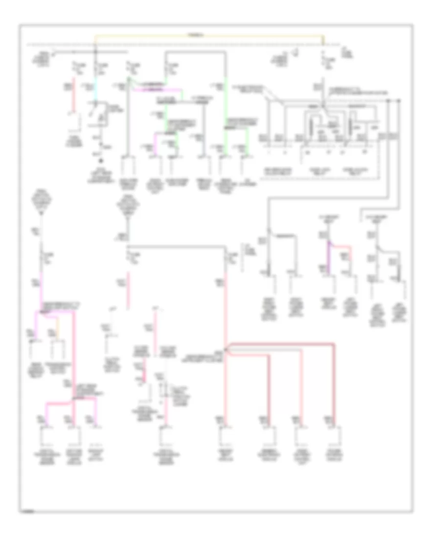 https://portal-diagnostov.com/license.html
Automotive Electricians Portal FZCO
Automotive Electricians Portal FZCO
https://portal-diagnostov.com/license.html
https://portal-diagnostov.com/license.html
Automotive Electricians Portal FZCO
Automotive Electricians Portal FZCOList of elements for Power Distribution Wiring Diagram (3 of 4) for Ford Explorer 1998:
- (in breakout to liftgate washer pump motor)
- (left rear of engine compartment) s120
- (near breakout to cd changer) s243
- (near breakout to headlamp switch) s207
- (near brekout to instrument cluster) s284
- 2dr
- 4dr
- A/t
- Amplifier (premium sound)
- Backup lamp switch
- Cd changer
- Cigar lighter
- Clutch pedal position switch
- Clutch pedal position switch jumper
- Daytime running lamps module
- Digital transmission range sensor
- Door lock relay
- Door unlock relay
- Driver's door unlock relay
- From d fuse 25 (diagram 2 of 4)
- From ignition switch a2 (diagram 2 of 4)
- From ignition switch sta (diagram 2 of 4)
- Fuse 10a
- Fuse 15a
- Fuse 25a
- Fuse 7.5a
- G104 (left rear of engine compartment)
- Generic electronic module
- I/p fuse panel
- Left front power seat control switch
- Left power lumbar seat switch
- M/t
- Memory seat module
- Nca
- Pnk
- Power antenna module
- Premium sound radio
- Radio or front control unit
- Rear integrated control panel
- Rear window defrost relay
- Right front power seat control switch
- Right power lumbar seat switch
- S200
- S282 (near breakout to instrument cluster)
- S303
- Subwoofer amplifier
- To fuse 26 (diagram 4 of 4)
- Transmission control switch
- Turn/ hazard flasher
- W/ electronics group only
- W/ high series console
- W/ lux/jbl and radio
- W/ memory seat
- W/ premium sound
- W/o high series console
- W/o memory seat
Power Distribution Wiring Diagram (4 of 4) for Ford Explorer 1998
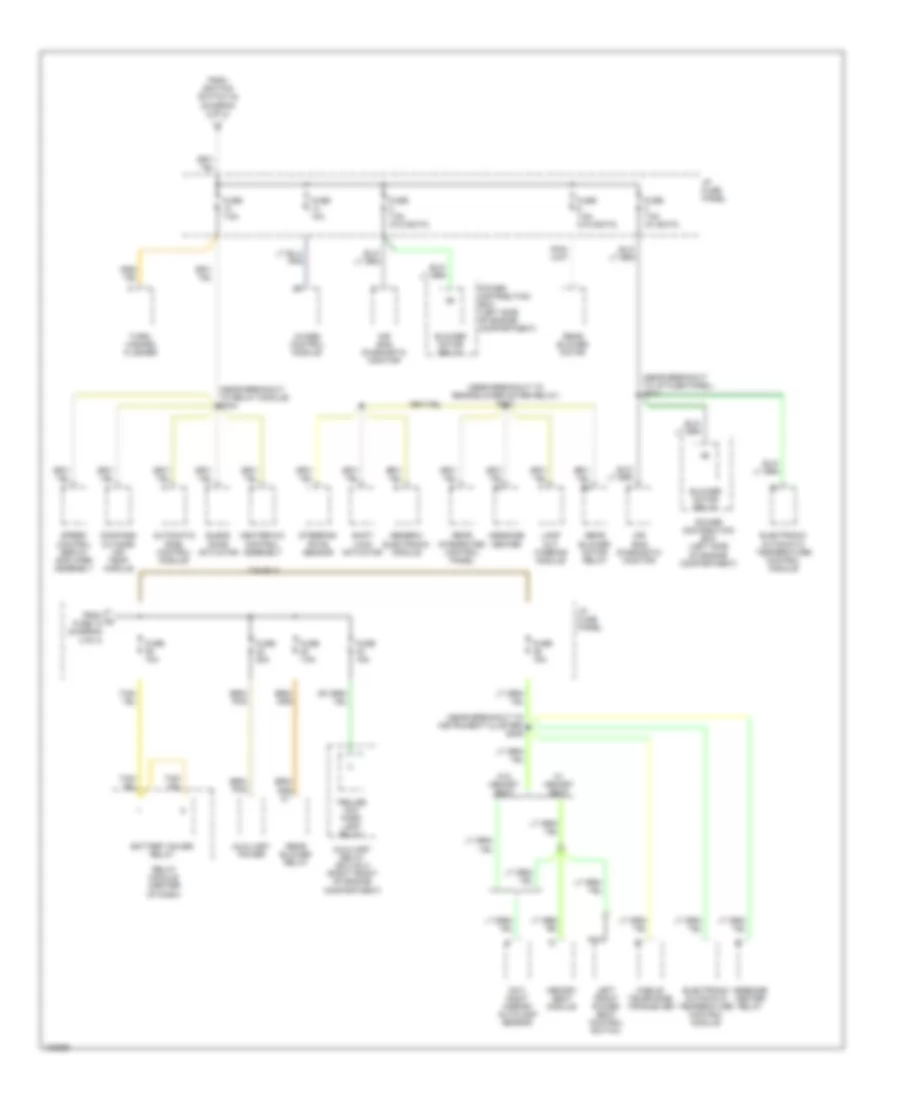 https://portal-diagnostov.com/license.html
Automotive Electricians Portal FZCO
Automotive Electricians Portal FZCO
https://portal-diagnostov.com/license.html
https://portal-diagnostov.com/license.html
Automotive Electricians Portal FZCO
Automotive Electricians Portal FZCOList of elements for Power Distribution Wiring Diagram (4 of 4) for Ford Explorer 1998:
- (near breakout to i/p fuse panel) s217
- (near breakout to instrument cluster) s209
- (near breakout to rear blower moter relay) s210
- (near breakout to relay module) s244
- 4wabs control module
- Air bag diagnostic monitor
- Automatic ride control module
- Auxiliary power
- Auxiliary relay box no 2 (right front of engine compartment)
- Battery saver relay
- Blend door actuator
- Blower motor relay
- Compass/ outside air temp module
- Day/ night mirror/ autolamp sensor
- Electronic automatic temperature control module
- From fuse 18 (diagram 3 of 4)
- From ignition switch a4 (diagram 2 of 4)
- Fuse 10a
- Fuse 15a
- Fuse 20a
- Fuse 7.5a
- Fuse 7.5a (w/ eatc)
- Fuse 7.5a (w/o eatc)
- Generic electronic module
- Heater/a/c control assembly
- I/p fuse panel
- Lamp out warning module
- Left front power seat control switch
- Memory seat module
- Message center
- Message center relay
- Mobile telephone tranceiver
- Nca
- Power distribution box (left side of engine compartment)
- Rear blower motor
- Rear blower motor relay
- Rear blower relay
- Rear integrated control panel
- Relay module (center of dash)
- Shift lock actuator
- Speed control servo/ amplifier assembly
- Steering rate sensor
- Trailer tow park lamp relay
- Turn/ hazard flasher
- W/ memory seat
- W/o memory seat
POWER DOOR LOCKS
Power Door Lock Wiring Diagram for Ford Explorer 1998
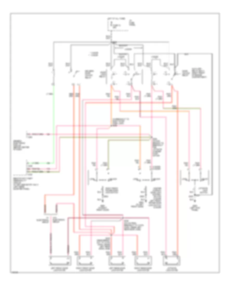 https://portal-diagnostov.com/license.html
Automotive Electricians Portal FZCO
Automotive Electricians Portal FZCO
https://portal-diagnostov.com/license.html
https://portal-diagnostov.com/license.html
Automotive Electricians Portal FZCO
Automotive Electricians Portal FZCOList of elements for Power Door Lock Wiring Diagram for Ford Explorer 1998:
- (2 door) (4 door)
- (in breakout to right stop/ park lamp) s305
- * **
- * 2 door 4 door
- * 87a
- 2 door
- 4 door
- Auxiliary relay box 2 (right front of engine compartment)
- C280
- C336
- C338
- Door lock relay
- Door unlock relay
- Driver's door unlock relay
- Fuse 18 25a
- G200 (left kick panel)
- G500 (in left front door)
- G600 (in right front door)
- Generic electronic module (behind center of dash)
- Hot at all times
- I/p fuse panel
- Left front door lock motor
- Left rear door lock motor
- Liftgate lock motor
- Liftgate lock switch
- Lock
- Master window/ door lock control switch (4 door) left front power door lock switch (2 door)
- Remote anti-theft personality module (w/ keyless entry only) (left rear quarter panel)
- Right front door lock motor
- Right front power door lock switch
- Right rear door lock motor
- S300 (in main branch to breakout for liftgate washer pump motor)
- S302
- S303
- S339 (510 mm from breakout to 10 pin conn, inside left rear door jamb)
- S340 (near break- out to 10 pin conn, inside left rear door jamb)
- S500
- S602
- Unlck
- Unlock
- W/ electronic group
- W/o electronic group
POWER MIRRORS
Photochromic Mirror Wiring Diagram for Ford Explorer 1998
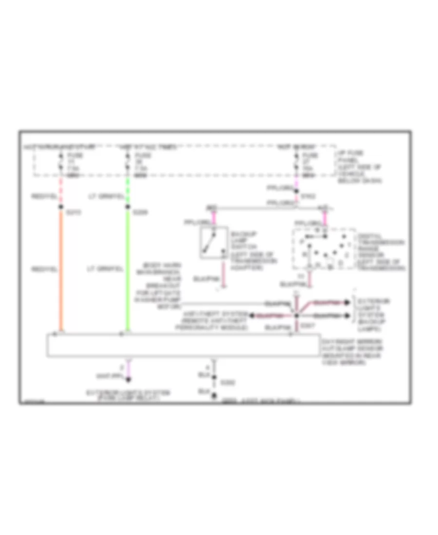 https://portal-diagnostov.com/license.html
Automotive Electricians Portal FZCO
Automotive Electricians Portal FZCO
https://portal-diagnostov.com/license.html
https://portal-diagnostov.com/license.html
Automotive Electricians Portal FZCO
Automotive Electricians Portal FZCOList of elements for Photochromic Mirror Wiring Diagram for Ford Explorer 1998:
- (body harn main branch, near breakout for liftgate washer pump motor)
- (left kick panel)
- A/t
- Anti-theft system (remote anti-theft personality module)
- Backup lamp switch (left side of transmission adapter)
- Day/night mirror/ autolamp sensor (mounted in rear view mirror)
- Digital transmission range sensor (left side of transmission)
- Exterior lights system (backup lamps)
- Exterior lights system (park lamp relay)
- Fuse 15a mini
- Fuse 7.5a mini
- G200
- Hot at all times
- Hot in run
- Hot in run and start
- I/p fuse panel (left side of vehicle, below dash)
- M/t
- S162
- S202
- S209
- S213
- S307
Power Mirror Wiring Diagram for Ford Explorer 1998
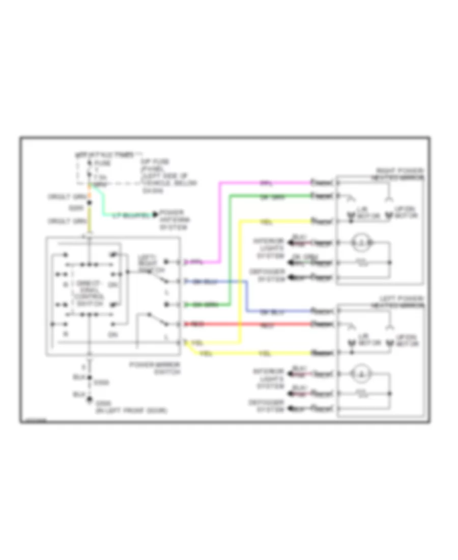 https://portal-diagnostov.com/license.html
Automotive Electricians Portal FZCO
Automotive Electricians Portal FZCO
https://portal-diagnostov.com/license.html
https://portal-diagnostov.com/license.html
Automotive Electricians Portal FZCO
Automotive Electricians Portal FZCOList of elements for Power Mirror Wiring Diagram for Ford Explorer 1998:
- Defogger system
- Direct- ional control switch
- Fuse 7.5a mini
- G500 (in left front door)
- Hot at all times
- I/p fuse panel (left side of vehicle, below dash)
- Interior lights system
- L/r m motor
- L/r motor
- Left power/ heated mirror
- Left/ right switch
- Nca
- Power antenna system
- Power mirror switch
- Red
- Right power/ heated mirror
- S265
- S500
- Up/dn m motor
POWER SEATS
Power & Lumbar Seat Wiring Diagram for Ford Explorer 1998
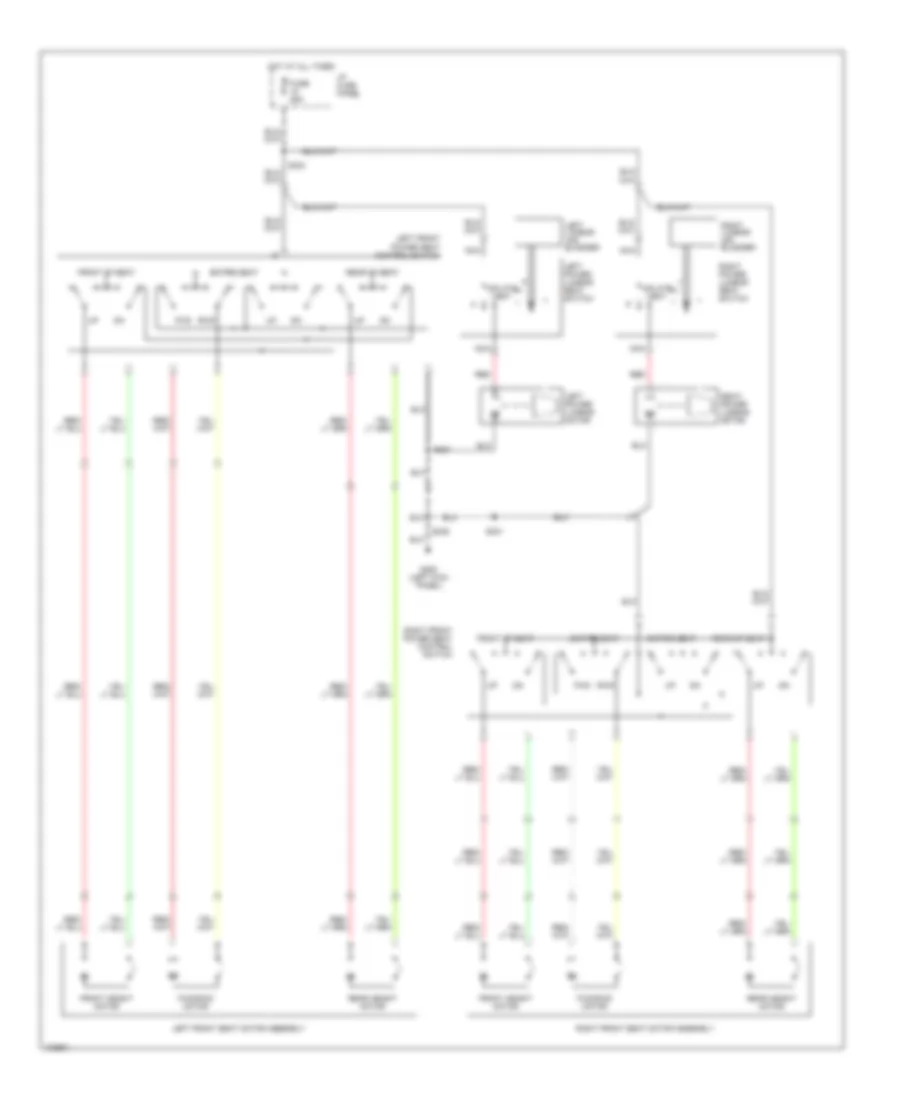 https://portal-diagnostov.com/license.html
Automotive Electricians Portal FZCO
Automotive Electricians Portal FZCO
https://portal-diagnostov.com/license.html
https://portal-diagnostov.com/license.html
Automotive Electricians Portal FZCO
Automotive Electricians Portal FZCOList of elements for Power & Lumbar Seat Wiring Diagram for Ford Explorer 1998:
- Entire seat
- Front height motor
- Front of seat
- Fuse 25a
- Fwd/rwd motor
- G200 (left kick panel)
- Hot at all times
- I/p fuse panel
- Inflate
- Left front power seat control switch
- Left front seat motor assembly
- Left lumbar air bladder
- Left power lumbar motor
- Left power lumbar seat switch
- Nca
- Rear height motor
- Rear of seat
- Red
- Right front power seat control switch
- Right front seat motor assembly
- Right lumbar air bladder
- Right power lumbar motor
- Right power lumbar seat switch
- Rwd fwd
- S235
- S301
- S303
- S321
- Vent
POWER TOP/SUNROOF
Power Top/Sunroof Wiring Diagrams for Ford Explorer 1998
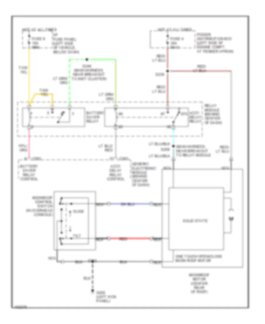 https://portal-diagnostov.com/license.html
Automotive Electricians Portal FZCO
Automotive Electricians Portal FZCO
https://portal-diagnostov.com/license.html
https://portal-diagnostov.com/license.html
Automotive Electricians Portal FZCO
Automotive Electricians Portal FZCOList of elements for Power Top/Sunroof Wiring Diagrams for Ford Explorer 1998:
- (main harness, near breakout to inst cluster)
- (main harness, near breakout to relay module
- Accy 87a delay relay
- Accy delay relay control
- Battery saver relay
- Battery saver relay control
- C283
- Fuse 4 30a maxi
- Fuse 8 10a mini
- G200 (left kick panel)
- Generic electronic module (behind center of dash)
- Hot at all times
- I/p fuse panel (left side of vehicle, below dash)
- Moonroof control switch (in overhead console)
- Moonroof motor (center rear of roof)
- Nca
- One touch open/close moon roof motor
- Power distribution box (left side of engine compt, at fender apron)
- Red
- Relay module (behind center of dash)
- S202
- S236
- S246
- S259
- Slide
- Solid state
- Tilt
POWER WINDOWS
Power Window Wiring Diagram, 2 Door for Ford Explorer 1998
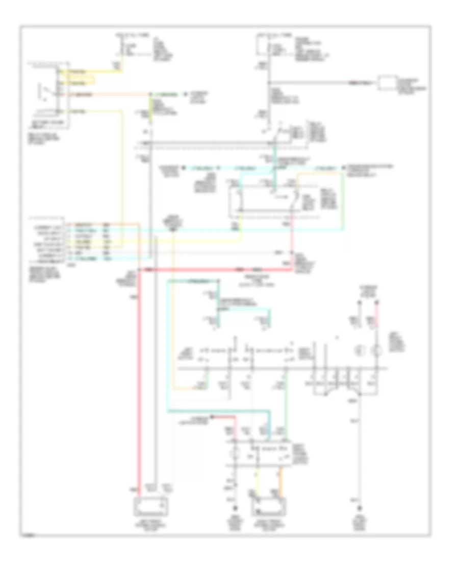 https://portal-diagnostov.com/license.html
Automotive Electricians Portal FZCO
Automotive Electricians Portal FZCO
https://portal-diagnostov.com/license.html
https://portal-diagnostov.com/license.html
Automotive Electricians Portal FZCO
Automotive Electricians Portal FZCOList of elements for Power Window Wiring Diagram, 2 Door for Ford Explorer 1998:
- (near breakout to lh pwr mirror) s504
- (near breakout to radio) s272
- (near breakout to relay mod) s259
- 87a
- Accy delay
- Accy delay relay
- Batt saver
- Battery saver relay
- C283
- Current hi
- Current low
- Down input
- Fuse 10a
- G500 (in left front door)
- G600 (in right front door)
- Generic elec- tronic module (behind center of dash)
- Hot at all times
- I/p fuse panel (below left side of dash)
- Interior lights system
- Left front power window motor
- Left front power window switch
- Left front switch
- Maxi fuse 4 30a
- Moonroof control switch
- Moonroof motor (center rear of roof)
- One touch dn
- One touch down relay
- Power distribution box (left side of engine compt, at fender apron)
- Red
- Relay module (behind center of dash)
- Resistance wire (0.015 +/- 0.001 ohm)
- Right front power window motor
- Right front power window switch
- Right front switch
- S236 (near breakout to headlamp sw)
- S246 (near breakout to cluster)
- S260 (near breakout to parking brake sw)
- S270 (near breakout to relay module)
- S271 (near breakout to radio)
- S500
- S602
- Transmissions system (torque on demand relay)
- Up input
Power Window Wiring Diagram, 4 Door for Ford Explorer 1998
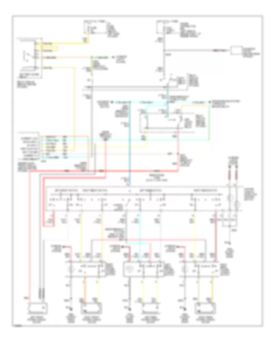 https://portal-diagnostov.com/license.html
Automotive Electricians Portal FZCO
Automotive Electricians Portal FZCO
https://portal-diagnostov.com/license.html
https://portal-diagnostov.com/license.html
Automotive Electricians Portal FZCO
Automotive Electricians Portal FZCOList of elements for Power Window Wiring Diagram, 4 Door for Ford Explorer 1998:
- (near breakout to 10 pin conn, in left rear dr jamb) s314
- (near breakout to radio) s271
- (near breakout to radio) s272
- (near breakout to relay mod) s259
- 87a
- Accy delay
- Accy delay relay
- Batt saver
- Battery saver relay
- C283
- Current hi
- Current low
- Down input
- Fuse 10a
- G500 (in left front door)
- G600 (in right front door)
- G700 (in left rear door)
- G800 (in right rear door)
- Generic elec- tronic module (behind center of dash)
- Hot at all times
- I/p fuse panel (below left side of dash)
- Interior lights system
- Left front power window motor
- Left front switch
- Left rear power window motor
- Left rear power window switch
- Left rear switch
- Master window/ door lock control switch
- Maxi fuse 4 30a
- Moonroof control switch
- Moonroof motor (center rear of roof)
- One touch dn
- One touch down relay
- Power distribution box (left side of engine compt, at fender apron)
- Red
- Relay module (behind center of dash)
- Resistance wire (0.015 +/- 0.001 ohm)
- Right front power window motor
- Right front power window switch
- Right front switch
- Right rear power window motor
- Right rear power window switch
- Right rear switch
- S236
- S246 (near breakout to cluster)
- S260 (near breakout to parking brake sw)
- S270 (near breakout to relay module)
- S500
- S602
- S700
- S800
- Transmissions system (torque on demand relay)
- Up input
- Window lock switch
RADIO
Base Radio, with High Series Console for Ford Explorer 1998
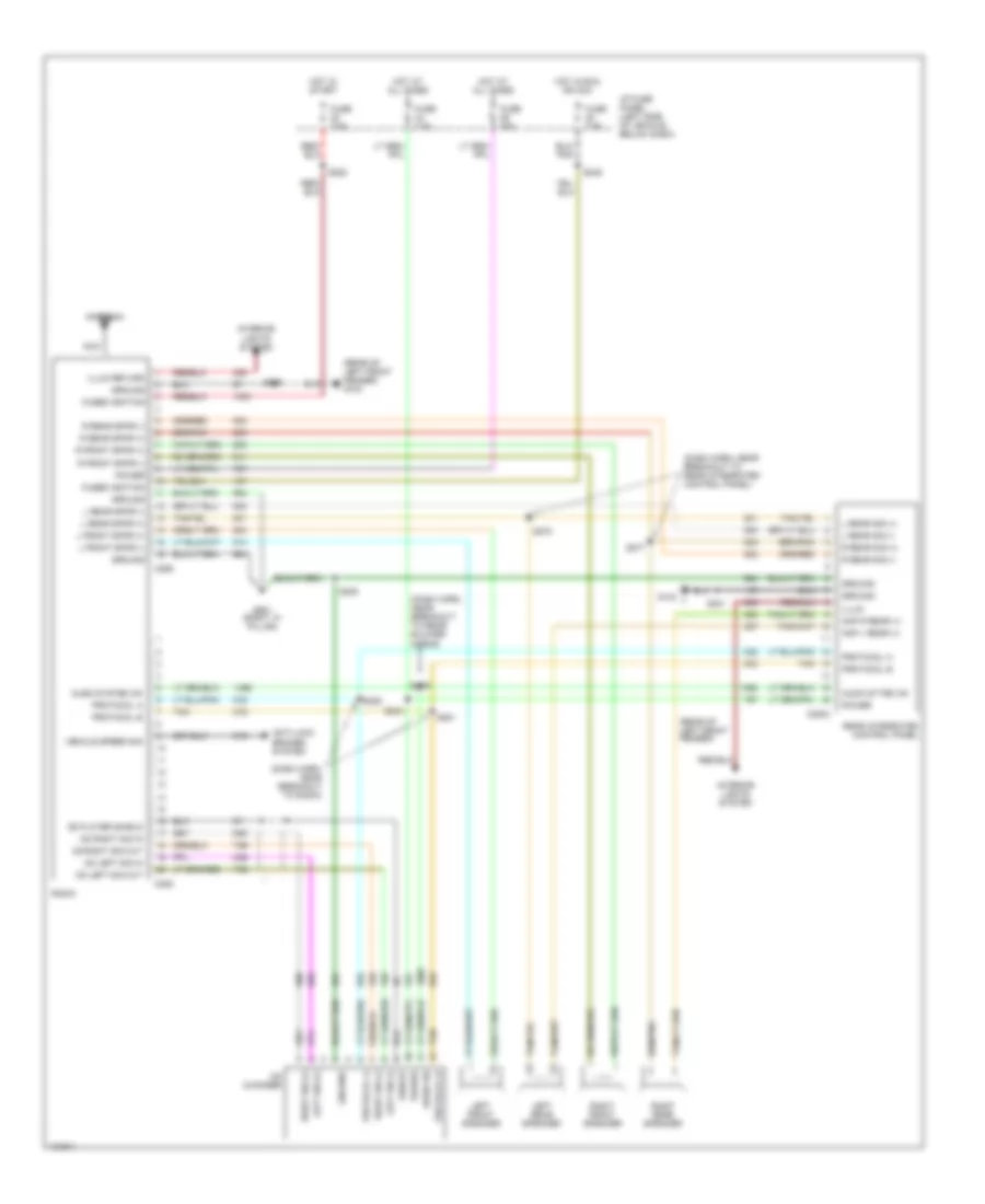 https://portal-diagnostov.com/license.html
Automotive Electricians Portal FZCO
Automotive Electricians Portal FZCO
https://portal-diagnostov.com/license.html
https://portal-diagnostov.com/license.html
Automotive Electricians Portal FZCO
Automotive Electricians Portal FZCOList of elements for Base Radio, with High Series Console for Ford Explorer 1998:
- (dash harn, near breakout to radio)
- (dash harn, near breakout to rear blower moror
- (dash harn, near breakout to rear integrated control panel)
- (rear of left front fender)
- (rear of left front fender) g104
- Amp l rear (+)
- Amp r rear (+)
- Antenna
- Anti-lock brakes system
- Audio on
- Audio system on
- Audio sytem on
- C2003
- C228
- C256
- Cd changer
- Cd left sig in
- Cd left sig out
- Cd player shield
- Cd right sig in
- Cd right sig out
- Fuse 25a
- Fuse 7.5a
- Fused ignition
- G104
- G901 (right "a" pillar)
- Ground
- Hot at all times
- Hot in run or acc
- Hot in start
- I/p fuse panel (left side of vehicle, below dash)
- Illum
- Illum return
- Interior lights system
- L front spkr (+)
- L front spkr (-)
- L rear sig (+)
- L rear sig (-)
- L rear spkr (+)
- L rear spkr (-)
- Left front speaker
- Left rear speaker
- Left sig (+)
- Left sig (-)
- Nca
- Power
- Protocol a
- Protocol b
- R front spkr (+)
- R front spkr (-)
- R rear sig (+)
- R rear sig (-)
- R rear spkr (+)
- R rear spkr (-)
- Radio
- Rear integrated control panel
- Right front speaker
- Right rear speaker
- Right sig (+)
- Right sig (-)
- S200
- S205
- S231
- S243
- S245
- S277
- S278
- S279
- S280
- S281
- S282
- Shield
- Tan
- Vehicle speed sig
Base Radio, without High Series Console for Ford Explorer 1998
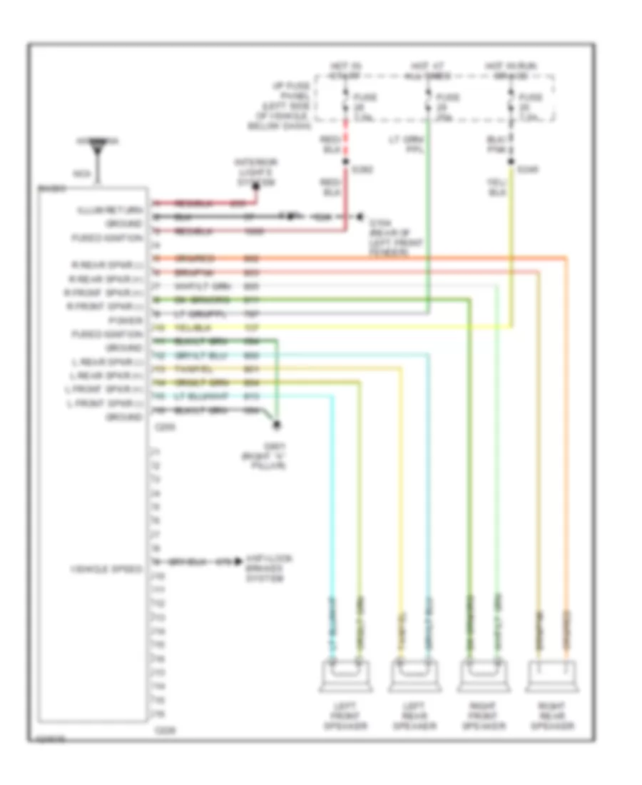 https://portal-diagnostov.com/license.html
Automotive Electricians Portal FZCO
Automotive Electricians Portal FZCO
https://portal-diagnostov.com/license.html
https://portal-diagnostov.com/license.html
Automotive Electricians Portal FZCO
Automotive Electricians Portal FZCOList of elements for Base Radio, without High Series Console for Ford Explorer 1998:
- Antenna
- Anti-lock brakes system
- C228
- C256
- Fuse 25a
- Fuse 7.5a
- Fused ignition
- G104 (rear of left front fender)
- G901 (right "a" pillar)
- Ground
- Hot at all times
- Hot in run or acc
- Hot in start
- I/p fuse panel (left side of vehicle, below dash)
- Illum return
- Interior lights system
- L front spkr (+)
- L front spkr (-)
- L rear spkr (+)
- L rear spkr (-)
- Left front speaker
- Left rear speaker
- Nca
- Power
- R front spkr (+)
- R front spkr (-)
- R rear spkr (+)
- R rear spkr (-)
- Radio
- Right front speaker
- Right rear speaker
- S200
- S245
- S282
- Vehicle speed
Premium Sound Radio Wiring Diagram, with High Series Console for Ford Explorer 1998
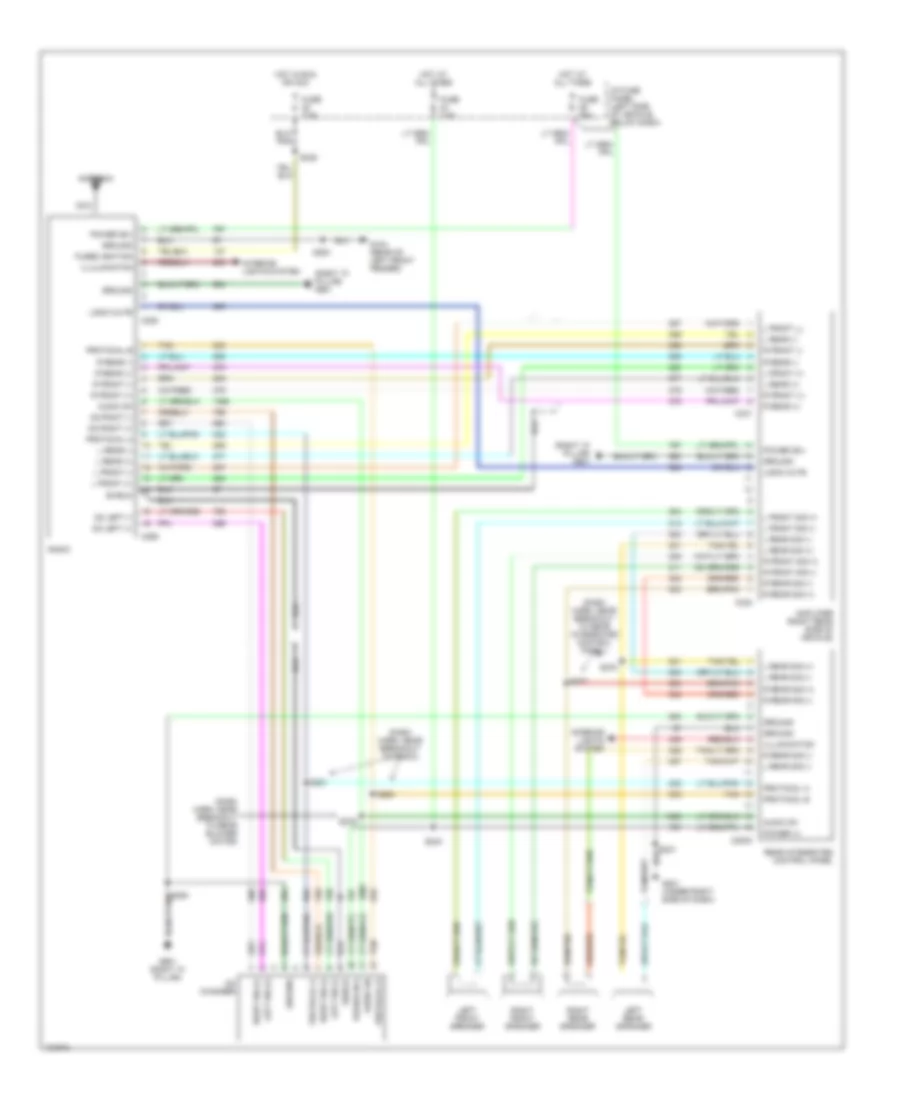 https://portal-diagnostov.com/license.html
Automotive Electricians Portal FZCO
Automotive Electricians Portal FZCO
https://portal-diagnostov.com/license.html
https://portal-diagnostov.com/license.html
Automotive Electricians Portal FZCO
Automotive Electricians Portal FZCOList of elements for Premium Sound Radio Wiring Diagram, with High Series Console for Ford Explorer 1998:
- (dash harn, near breakout to radio)
- (dash harn, near breakout to rear blower motor)
- (dash harn, near breakout to rear integrated control panel)
- (right "a" pillar) g901
- Amplifier (right rear side of vehicle)
- Antenna
- Audio on
- C2003
- C228
- C256
- C331
- C332
- Cd changer
- Cd left (+)
- Cd left (-)
- Cd right (+)
- Cd right (-)
- Fuse 25a
- Fuse 7.5a
- Fused ignition
- G104 (rear of left front fender)
- G201 (under right side of dash)
- G901 (right "a" pillar)
- Ground
- Hot at all times
- Hot in run or acc
- I/p fuse panel (left side of vehicle, below dash)
- Iillumination
- Illulminaton
- Interior lights system
- L front (+)
- L front (-)
- L front (_)
- L front sig (+)
- L front sig (-)
- L rear (+)
- L rear (-)
- L rear sig (+)
- L rear sig (-)
- Left front speaker
- Left rear speaker
- Left sig (+)
- Left sig (-)
- Logic mute
- Nca
- Power (+)
- Power (b+)
- Protocal a
- Protocal b
- Protocol a
- Protocol b
- R front (+)
- R front (-)
- R front sig (+)
- R front sig (-)
- R rear (+)
- R rear (-)
- R rear sig (+)
- R rear sig (-)
- Radio
- Rear integrated control panel
- Right front speaker
- Right rear speaker
- Right sig (+)
- Right sig (-)
- S200
- S205
- S231
- S243
- S245
- S277
- S278
- S279
- S280
- S281
- Shield
- Tan
Premium Sound Radio Wiring Diagram, with Mach Sound System for Ford Explorer 1998
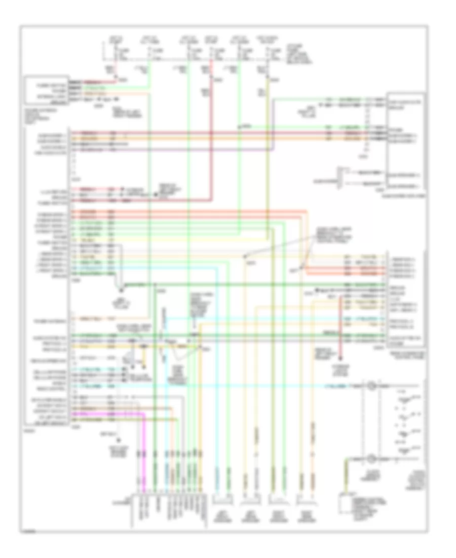 https://portal-diagnostov.com/license.html
Automotive Electricians Portal FZCO
Automotive Electricians Portal FZCO
https://portal-diagnostov.com/license.html
https://portal-diagnostov.com/license.html
Automotive Electricians Portal FZCO
Automotive Electricians Portal FZCOList of elements for Premium Sound Radio Wiring Diagram, with Mach Sound System for Ford Explorer 1998:
- (dash harn, near breakout to radio)
- (dash harn, near breakout to rear blower motor)
- (dash harn, near breakout to rear integrated control panel)
- (dash harn, near ignition switch
- (rear of left front fender)
- (rear of left front fender) g104
- Amp l rear (+)
- Amp r rear (+)
- Antenna logic
- Anti-lock brakes system
- Audio on
- Audio shield
- Audio system on
- Audio sytem on
- Audio/ climate control switch assembly
- Band
- C171
- C2003
- C215
- C228
- C256
- C333
- C388
- Cd changer
- Cd left sig in
- Cd left sig out
- Cd player shield
- Cd right sig in
- Cd right sig out
- Cellular phone
- Cellular telephone
- Clock- spring assembly
- Down
- Fuse 25a
- Fuse 7.5a
- Fused ignition
- G104
- G901 (right "a" pillar)
- Ground
- High audio mute
- Hot at all times
- Hot in run or acc
- Hot in start
- I/p fuse panel (left side of vehicle, below dash)
- Illum
- Illum return
- Interior lights
- Interior lights system
- L front spkr (+)
- L front spkr (-)
- L rear sig (+)
- L rear sig (-)
- L rear spkr (+)
- L rear spkr (-)
- Left front speaker
- Left rear speaker
- Left sig (+)
- Left sig (-)
- Mem
- Nca
- Power
- Power antenna
- Power antenna module (on antenna mast)
- Protocol a
- Protocol b
- R front spkr (+)
- R front spkr (-)
- R rear sig (+)
- R rear sig (-)
- R rear spkr (+)
- R rear spkr (-)
- Radio
- Radio control
- Rear integrated control panel
- Right front speaker
- Right rear speaker
- Right sig (+)
- Right sig (-)
- S200
- S204
- S205
- S229
- S231
- S243
- S245
- S277
- S278
- S279
- S280
- S281
- S282
- S284
- S352
- Shield
- Speed control servo/amplifier assembly (right rear of engine compt)
- Sub speaker (+)
- Sub speaker (-)
- Subwoofer
- Subwoofer (+)
- Subwoofer (-)
- Subwoofer amplifier
- Tan
- Vehicle speed sig
Premium Sound Radio Wiring Diagram, without High Series Console for Ford Explorer 1998
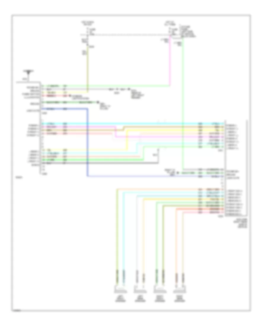 https://portal-diagnostov.com/license.html
Automotive Electricians Portal FZCO
Automotive Electricians Portal FZCO
https://portal-diagnostov.com/license.html
https://portal-diagnostov.com/license.html
Automotive Electricians Portal FZCO
Automotive Electricians Portal FZCOList of elements for Premium Sound Radio Wiring Diagram, without High Series Console for Ford Explorer 1998:
- (right "a" pillar) g901
- Amplifier (right rear side of vehicle)
- Antenna
- C228
- C256
- C331
- C332
- Fuse 25a
- Fuse 7.5a
- Fused ignition
- G104 (rear of left front fender)
- G901 (right "a" pillar)
- Ground
- Hot at all times
- Hot in run or acc
- I/p fuse panel (left side of vehicle, below dash)
- Illulminaton
- Interior lights system
- L front (+)
- L front (-)
- L front (_)
- L front sig (+)
- L front sig (-)
- L rear (+)
- L rear (-)
- L rear sig (+)
- L rear sig (-)
- Left front speaker
- Left rear speaker
- Logic mute
- Nca
- Power (b+)
- R front (+)
- R front (-)
- R front sig (+)
- R front sig (-)
- R rear (+)
- R rear (-)
- R rear sig (+)
- R rear sig (-)
- Radio
- Right front speaker
- Right rear speaker
- S200
- S245
- Shield
SHIFT INTERLOCKS
Shift Interlock Wiring Diagram for Ford Explorer 1998
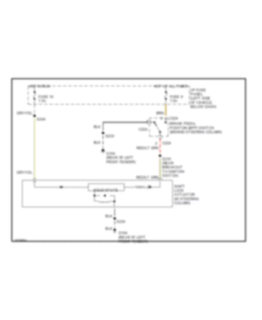 https://portal-diagnostov.com/license.html
Automotive Electricians Portal FZCO
Automotive Electricians Portal FZCO
https://portal-diagnostov.com/license.html
https://portal-diagnostov.com/license.html
Automotive Electricians Portal FZCO
Automotive Electricians Portal FZCOList of elements for Shift Interlock Wiring Diagram for Ford Explorer 1998:
- Brake pedal position (bpp) switch (behind steering column)
- C224
- Fuse 10 7.5a
- Fuse 9 7.5a
- G104 (rear of left front fender)
- Hot at all times
- Hot in run
- I/p fuse panel (left side of vehicle, below dash)
- S230
- S244
- Shift lock actuator (in steering column)
- Solid state
STARTING/CHARGING
Charging Wiring Diagram for Ford Explorer 1998
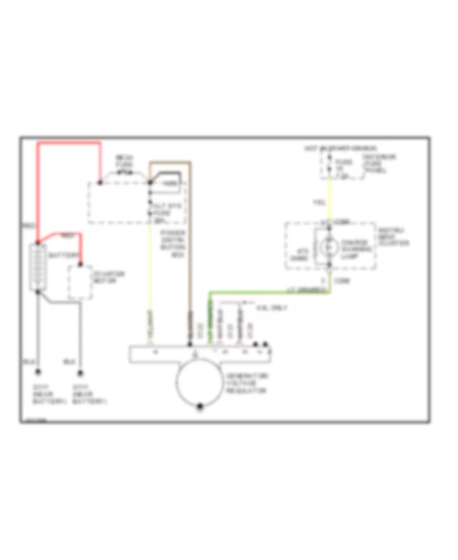 https://portal-diagnostov.com/license.html
Automotive Electricians Portal FZCO
Automotive Electricians Portal FZCO
https://portal-diagnostov.com/license.html
https://portal-diagnostov.com/license.html
Automotive Electricians Portal FZCO
Automotive Electricians Portal FZCOList of elements for Charging Wiring Diagram for Ford Explorer 1998:
- 4.0l only
- Alt sys fuse 30a
- Battery
- C120
- C121
- C122
- C288
- Charge warning lamp
- Fuse 7.5a
- G111 (near battery)
- Generator/ voltage regulator
- Hot in start or run
- Instru- ment cluster
- Interior fuse panel
- Mega fuse 175a
- Nca
- Ohms
- Power distri- bution box
- Red
- Starter motor
Starting Wiring Diagram, A/T for Ford Explorer 1998
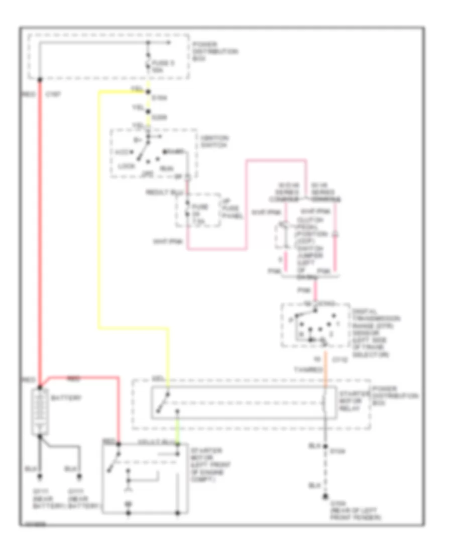 https://portal-diagnostov.com/license.html
Automotive Electricians Portal FZCO
Automotive Electricians Portal FZCO
https://portal-diagnostov.com/license.html
https://portal-diagnostov.com/license.html
Automotive Electricians Portal FZCO
Automotive Electricians Portal FZCOList of elements for Starting Wiring Diagram, A/T for Ford Explorer 1998:
- Acc
- Battery
- C112
- C197
- Clutch pedal position (ccp) switch jumper (left of dash)
- Digital transmission range (dtr) sensor (left side of trans selector)
- Fuse 5 50a
- Fuse 7.5a
- G104 (rear of left front fender)
- G111 (near battery)
- I/p fuse panel
- Ignition switch
- Lock
- Off
- Pnk
- Power distribution box
- Red
- Run
- S104
- S164
- S209
- Start
- Starter motor (left front of engine compt)
- Starter motor relay
- Tan/red
- W/ hi series console
- W/o hi series console
Starting Wiring Diagram, M/T for Ford Explorer 1998
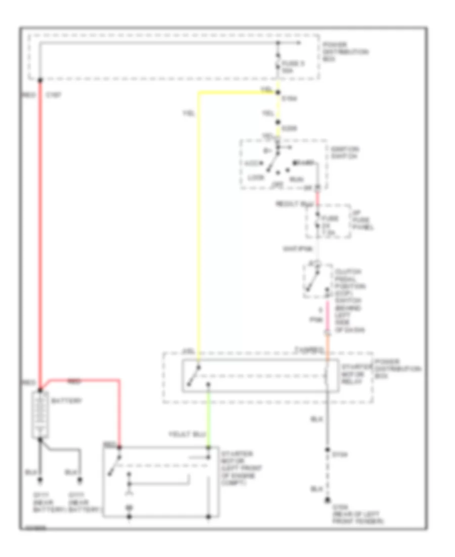 https://portal-diagnostov.com/license.html
Automotive Electricians Portal FZCO
Automotive Electricians Portal FZCO
https://portal-diagnostov.com/license.html
https://portal-diagnostov.com/license.html
Automotive Electricians Portal FZCO
Automotive Electricians Portal FZCOList of elements for Starting Wiring Diagram, M/T for Ford Explorer 1998:
- Acc
- Battery
- C197
- Clutch pedal position (ccp) switch (behind left side of dash)
- Fuse 5 50a
- Fuse 7.5a
- G104 (rear of left front fender)
- G111 (near battery)
- I/p fuse panel
- Ignition switch
- Lock
- Off
- Pnk
- Power distribution box
- Red
- Run
- S104
- S164
- S209
- Start
- Starter motor (left front of engine compt)
- Starter motor relay
- Tan/red
SUPPLEMENTAL RESTRAINTS
Supplemental Restraint Wiring Diagram for Ford Explorer 1998
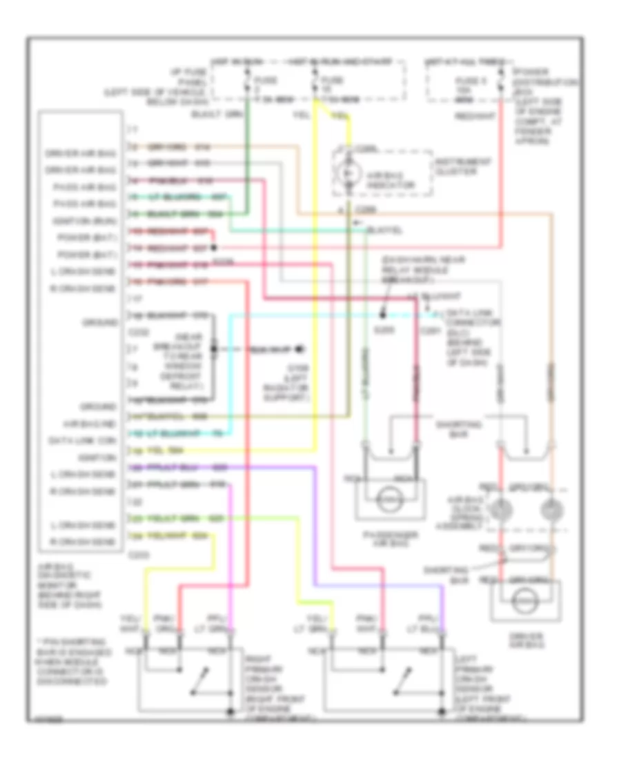 https://portal-diagnostov.com/license.html
Automotive Electricians Portal FZCO
Automotive Electricians Portal FZCO
https://portal-diagnostov.com/license.html
https://portal-diagnostov.com/license.html
Automotive Electricians Portal FZCO
Automotive Electricians Portal FZCOList of elements for Supplemental Restraint Wiring Diagram for Ford Explorer 1998:
- when module
- (dash harn, near relay module breakout)
- (near s232 breakout to rear window defrost relay)
- * pin shorting bar is engaged
- Air bag clock- spring assembly
- Air bag diagnostic monitor (behind right side of dash)
- Air bag ind
- Air bag indicator
- C232
- C233
- C288
- C291
- Connector is disconnected
- Data link con
- Data link connector (dlc) (behind left side of dash)
- Driver air bag
- Fuse 5 10a mini
- Fuse 7.5a mini
- G108 (left radiator support)
- Ground
- Hot at all times
- Hot in run
- Hot in run and start
- I/p fuse panel (left side of vehicle, below dash)
- Ignition
- Ignition (run)
- Instrument cluster
- L crash sens
- Left primary crash sensor (left front of engine compartment)
- Nca
- Pass air bag
- Passenger air bag
- Power (bat)
- Power distribution box (left side of engine compt, at fender apron)
- R crash sens
- Red
- Right primary crash sensor (right front of engine compartment)
- S239
- S255
- Shorting bar
TRANSMISSION
4.0L
4.0L OHV, Transmission Wiring Diagram, 5R55E for Ford Explorer 1998
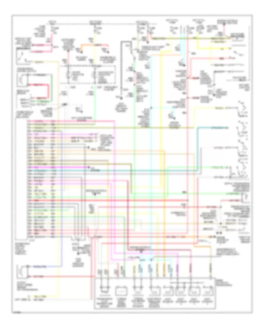 https://portal-diagnostov.com/license.html
Automotive Electricians Portal FZCO
Automotive Electricians Portal FZCO
https://portal-diagnostov.com/license.html
https://portal-diagnostov.com/license.html
Automotive Electricians Portal FZCO
Automotive Electricians Portal FZCOList of elements for 4.0L OHV, Transmission Wiring Diagram, 5R55E for Ford Explorer 1998:
- (in breakout for pcm)
- (left radiator support) g108
- (near breakout to 16-pin conn at rear of eng compt)
- (near breakout to 4wabs module)
- (near breakout to fuel injector 6)
- (not used)
- (right kick panel)
- 4wabs module (left side of eng compt)
- 5r55e automatic transmission
- A/c system
- Air condi- tioning & engine controls systems
- Anti-lock brakes system
- Back-up lamp switch, drl module, rear window defog relay
- Battery junction box
- Brake pedal position switch
- C172
- C286
- C287
- Canister vent solenoid
- Data link connector (partial) (left side of dash)
- Day/night mirror
- Digital transmission range sensor (left side of transmission)
- Dimmer relay & instrument cluster
- Electronic pressure control solenoid
- Engine controls system
- Engine controls system (ignition)
- Engine coolant temperature sensor (front of engine left of throttle body)
- Fuse 10a
- Fuse 15a
- Fuse 25a
- Fuse 7.5a
- Fuse junction panel (left side of dash)
- G104 (rear of left front fender)
- G108 (left radiator support)
- G203
- Hot at all times
- Hot in run
- Hot in run or start
- Instrument cluster
- Instrument cluster system (headlamp switch)
- Malfunction indicator lamp (check engine)
- Maxi fuse 30a
- O/d off indicator lamp (tcil)
- Output shaft speed sensor (on transmission)
- Passive anti-theft system module
- Pcm power relay
- Pcm power relay diode
- Powertrain control module (through firewall)
- R p
- Rear axle sensor
- Red
- Red/pnk
- S101
- S105
- S123 (135 mm from branch to fuel pump relay)
- S136 (405 mm from bmap sensor breakout)
- S137
- S142 (100 mm from breakout to 4-pin conn at righ rear of eng)
- S146
- S147 (near breakout to auxiliary relay box 3)
- S166
- S167 (near breakout to fuel injector 6)
- S168
- S179
- S180
- S205
- S206
- S213
- S215 (near breakout to ignition switch)
- S230
- Sens hi
- Sens lo
- Shift solenoid
- Throttle postion sensor
- Torque converter clutch solenoid
- Transmission control switch
- Transmission fluid temperature sensor
- Turbine shaft speed sensor
- Vs out
4.0L SOHC, Transmission Wiring Diagram, 5R55E for Ford Explorer 1998
 https://portal-diagnostov.com/license.html
Automotive Electricians Portal FZCO
Automotive Electricians Portal FZCO
https://portal-diagnostov.com/license.html
https://portal-diagnostov.com/license.html
Automotive Electricians Portal FZCO
Automotive Electricians Portal FZCOList of elements for 4.0L SOHC, Transmission Wiring Diagram, 5R55E for Ford Explorer 1998:
- (in breakout for pcm)
- (left radiator support) g108
- (near breakout to 16-pin conn at rear of eng compt)
- (near breakout to 4wabs module)
- (near breakout to fuel injector 6)
- (not used)
- (right kick panel)
- 4wabs module (left side of eng compt)
- 5r55e automatic transmission
- A/c system
- Air condi- tioning & engine controls systems
- Anti-lock brakes system
- Back-up lamp switch, drl module, rear window defog relay
- Battery junction box
- Brake pedal position switch
- C172
- C286
- C287
- Canister vent solenoid
- Data link connector (partial) (left side of dash)
- Day/night mirror
- Digital transmission range sensor (left side of transmission)
- Dimmer relay & instrument cluster
- Electronic pressure control solenoid
- Engine controls system
- Engine controls system (ignition)
- Engine coolant temperature sensor (front of engine left of throttle body)
- Fuse 10a
- Fuse 15a
- Fuse 25a
- Fuse 7.5a
- Fuse junction panel (left side of dash)
- G104 (rear of left front fender)
- G108 (left radiator support)
- G203
- Hot at all times
- Hot in run
- Hot in run or start
- Instrument cluster
- Instrument cluster system (headlamp switch)
- Malfunction indicator lamp (check engine)
- Maxi fuse 30a
- O/d off indicator lamp (tcil)
- Output shaft speed sensor (on transmission)
- Passive anti-theft system module
- Pcm power relay
- Pcm power relay diode
- Powertrain control module (through firewall)
- R p
- Rear axle sensor
- Red
- Red/pnk
- S101
- S105
- S123 (135 mm from branch to fuel pump relay)
- S136 (405 mm from bmap sensor breakout)
- S137
- S142 (100 mm from breakout to 4-pin conn at righ rear of eng)
- S146
- S147 (near breakout to auxiliary relay box 3)
- S166
- S167 (near breakout to fuel injector 6)
- S168
- S179
- S180
- S205
- S206
- S213
- S215 (near breakout to ignition switch)
- S230
- Sens hi
- Sens lo
- Shift solenoid
- Throttle postion sensor
- Torque converter clutch solenoid
- Transmission control switch
- Transmission fluid temperature sensor
- Turbine shaft speed sensor
- Vs out
Electronic Transfer Case Wiring Diagram for Ford Explorer 1998
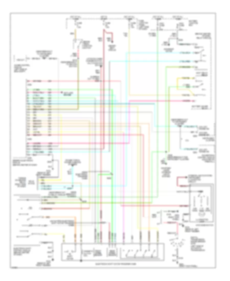 https://portal-diagnostov.com/license.html
Automotive Electricians Portal FZCO
Automotive Electricians Portal FZCO
https://portal-diagnostov.com/license.html
https://portal-diagnostov.com/license.html
Automotive Electricians Portal FZCO
Automotive Electricians Portal FZCOList of elements for Electronic Transfer Case Wiring Diagram for Ford Explorer 1998:
- (440 mm from electronic shift motor transfer case)
- (behind center of dash) relay module
- (in break out to gem) s250
- (left side of automatic transmission)
- (near break out to instrument cluster) s248
- (near break out to relay module)
- (near breakout for instrument cluster)
- (near breakout to instrument cluster) s247
- (near breakout to radio)
- (near electronic transfer case)
- 1.1k ohms
- 3.9k ohms
- 4.0l
- 4wabs control module (left side of eng compt)
- 4wd mode switch
- 4x4 high range ind
- 4x4 low range ind
- 4x4 low range ind c202
- 87a
- A/t
- Accy delay relay
- Anti-lock brakes
- Battery junction box
- Battery saver relay
- Brake pedal position switch
- C280
- C282
- C283
- C286
- Courtesy lamps (interior lights system)
- Digital transmission range sensor (dtr)
- Electronic shift control module (behind center of dash)
- Electronic shift motor transfer case
- Front speed sensor
- Fuse 10a
- Fuse 7.5a
- Fuse junction panel (left side of dash)
- G104 (rear of left front fender)
- G203 (right kick panel)
- Generic electronic module (behind center of dash)
- H2l
- Hot at all times
- Hot in start
- Illumination lamp
- Instrument cluster
- Interior lights system (instrument illumination circuit)
- L2h
- Liftgate wiper/ washer switch, multi-function switch
- M/t
- Magnetic clutch coil
- Maxi fuse 20a
- Maxi fuse 30a
- Memory seat module
- Mode
- Moonroof motor
- Ohms
- Power tops & power windows systems
- Powertrain control module (mounted on firewall)
- Rear speed sensor
- S108
- S200
- S215 (near breakout to ignition switch)
- S236
- S246
- S249
- S251
- S252
- S259
- Shift motor
- Solid state
- Torque on demand relay (right side of dash)
- Vss out
5.0L
5.0L, Transmission Wiring Diagram, 4R70W for Ford Explorer 1998
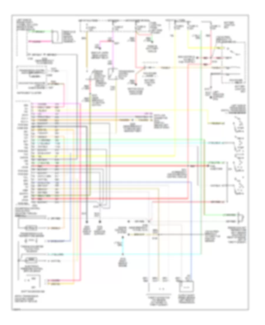 https://portal-diagnostov.com/license.html
Automotive Electricians Portal FZCO
Automotive Electricians Portal FZCO
https://portal-diagnostov.com/license.html
https://portal-diagnostov.com/license.html
Automotive Electricians Portal FZCO
Automotive Electricians Portal FZCOList of elements for 5.0L, Transmission Wiring Diagram, 4R70W for Ford Explorer 1998:
- (100 mm from breakout to throttle position sensor)
- (135 mm from breakout to fuel pump relay)
- (left radiator support) g108
- (left side of engine compt) 4 wheel anti-lock brake system (4wabs) module
- (left side of transmission) digital transmission range sensor
- 4r70w transmission (mounted under center of vehicle)
- Back-up lamps, rear window defrost relay
- Battery junction box
- Bpp
- Brake pedal position switch (behind steering column)
- C186
- C202
- C286
- C287
- Case gnd
- Data
- Data link connector (dlc) (partial) (behind left side of dash)
- Dlc (+)
- Dlc (-)
- Ect
- Electronic pressure control (epc) solenoid
- Eng controls, a/c relay, fuel pump rly
- Engine controls system
- Engine coolant temperature (ect) sensor (mounted on front of engine, left of throttle body)
- Epc
- Fuel injectors
- Fuse 10 30a
- Fuse 13 15a
- Fuse 19 25a
- Fuse 27 15a
- Fuse 6 10a
- Fuse 9 7.5a
- Fuse junction panel (left side of dash)
- G108 (left radiator support)
- G203 (right side of dash)
- Hot at all times
- Hot in run
- Hot in start or run
- Ignition coils, radio noise capacitor
- Instrument cluster
- Kapwr
- Malfunction indicator lamp (mil) (check engine)
- Mil
- Od off
- Oss
- Output shaft speed sensor (left rear of transmission)
- Passive anti-theft module
- Pcm power diode
- Pcm power relay
- Powertrain control module (pcm) (mounted through firewall)
- Pwr gnd
- R p
- Rear axle speed sensor (on axle assembly)
- Red
- S101 (in breakout for powertrain control module)
- S105
- S123
- S137
- S142 (right rear of engine)
- S146
- S166 (near breakout to fuel inj 6)
- S168 (near breakout to 4wabs mod)
- S206 (near breakout to ground g201, near battery)
- S207
- S215 (near breakout to ignition switch)
- Shift solenoids (ss)
- Sig rtn
- Ss1
- Ss2
- Tcc
- Tcil
- Tcs
- Tft
- Throttle position (tp) sensor (attached to throttle body)
- Torque converter clutch (tcc) solenoid
- Tr1
- Tr2
- Tr3
- Transmission control indicator lamp (tcil)
- Transmission control switch (tcs)
- Transmission fluid temperature sensor
- Vpwr
- Vref
- Vss
Electronic Transfer Case Wiring Diagram for Ford Explorer 1998
 https://portal-diagnostov.com/license.html
Automotive Electricians Portal FZCO
Automotive Electricians Portal FZCO
https://portal-diagnostov.com/license.html
https://portal-diagnostov.com/license.html
Automotive Electricians Portal FZCO
Automotive Electricians Portal FZCOList of elements for Electronic Transfer Case Wiring Diagram for Ford Explorer 1998:
- (440 mm from electronic shift motor transfer case)
- (behind center of dash) relay module
- (in break out to gem) s250
- (left side of automatic transmission)
- (near break out to instrument cluster) s248
- (near break out to relay module)
- (near breakout for instrument cluster)
- (near breakout to instrument cluster) s247
- (near breakout to radio)
- (near electronic transfer case)
- 1.1k ohms
- 3.9k ohms
- 4.0l
- 4wabs control module (left side of eng compt)
- 4wd mode switch
- 4x4 high range ind
- 4x4 low range ind
- 4x4 low range ind c202
- 87a
- A/t
- Accy delay relay
- Anti-lock brakes
- Battery junction box
- Battery saver relay
- Brake pedal position switch
- C280
- C282
- C283
- C286
- Courtesy lamps (interior lights system)
- Digital transmission range sensor (dtr)
- Electronic shift control module (behind center of dash)
- Electronic shift motor transfer case
- Front speed sensor
- Fuse 10a
- Fuse 7.5a
- Fuse junction panel (left side of dash)
- G104 (rear of left front fender)
- G203 (right kick panel)
- Generic electronic module (behind center of dash)
- H2l
- Hot at all times
- Hot in start
- Illumination lamp
- Instrument cluster
- Interior lights system (instrument illumination circuit)
- L2h
- Liftgate wiper/ washer switch, multi-function switch
- M/t
- Magnetic clutch coil
- Maxi fuse 20a
- Maxi fuse 30a
- Memory seat module
- Mode
- Moonroof motor
- Ohms
- Power tops & power windows systems
- Powertrain control module (mounted on firewall)
- Rear speed sensor
- S108
- S200
- S215 (near breakout to ignition switch)
- S236
- S246
- S249
- S251
- S252
- S259
- Shift motor
- Solid state
- Torque on demand relay (right side of dash)
- Vss out
WARNING SYSTEMS
Warning System Wiring Diagrams for Ford Explorer 1998
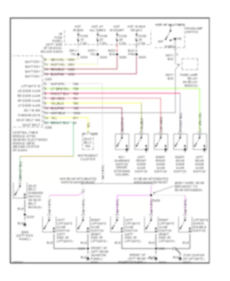 https://portal-diagnostov.com/license.html
Automotive Electricians Portal FZCO
Automotive Electricians Portal FZCO
https://portal-diagnostov.com/license.html
https://portal-diagnostov.com/license.html
Automotive Electricians Portal FZCO
Automotive Electricians Portal FZCOList of elements for Warning System Wiring Diagrams for Ford Explorer 1998:
- (body harn, near breakout to rear defogger)
- (front of left rear quarter panel)
- (front of left rear quarter panel) g414
- (top center of liftgate) g412
- Battery
- C280
- C283
- C288
- Central timer module (ctm)/ generic electronic module (gem) (behind center of dash)
- Fuse 7.5a
- G200 (left kick panel)
- G414
- Head
- Headlamp switch
- Hot at all times
- Hot in run
- Hot in run or acc
- Hot in start
- I/p fuse panel (left side of vehicle, below dash)
- Instrument cluster
- Key in ign
- Key warning switch (inside steering column)
- Left front door ajar switch
- Left liftgate ajar switch (left side of liftgate)
- Left rear door ajar switch
- Lf door ajar
- Liftgate in
- Liftgate wiper disable switch
- Lr door ajar
- Off
- Park
- Park lamp relay (in relay module)
- Park/head in
- Rf door ajar
- Right front door ajar switch
- Right liftgate ajar switch (right side of liftgate)
- Right rear door ajar switch
- Rr door ajar
- S235
- S242
- S244
- S245
- S282
- S404
- S405
- Seat belt
- Seat belt ind
- Seat belt warning switch (in seat belt buckle)
- W/ rear integrated wipe/wash/defrost
- W/o rear integrated wipe/wash/defrost
WIPER/WASHER
Front Wiper/Washer Wiring Diagram for Ford Explorer 1998
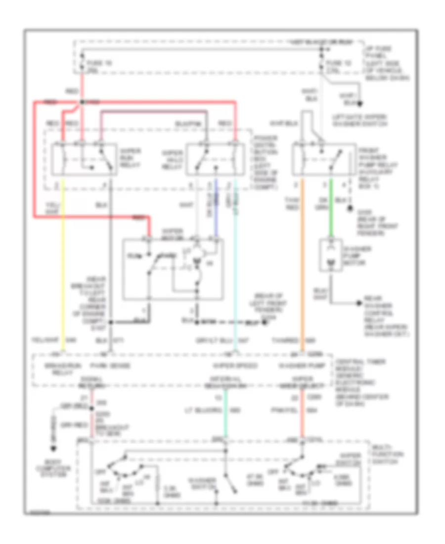 https://portal-diagnostov.com/license.html
Automotive Electricians Portal FZCO
Automotive Electricians Portal FZCO
https://portal-diagnostov.com/license.html
https://portal-diagnostov.com/license.html
Automotive Electricians Portal FZCO
Automotive Electricians Portal FZCOList of elements for Front Wiper/Washer Wiring Diagram for Ford Explorer 1998:
- (left side of vehicle, below dash)
- (near breakout to left rear corner of engine compt) s107
- (rear of left front fender) g104
- 103k ohms
- 11.3k
- 3.3k ohms
- 4.08k
- Body computer system
- Brake/run relay
- C210
- C280
- Central timer module/ generic electronic module (behind center of dash)
- Front washer pump relay (auxiliary relay box 1)
- Fuse 12 7.5a
- Fuse 16 30a
- G105 (rear of right front fender)
- Hot in acc or run
- I/p fuse panel
- Int max
- Int min
- Interval delay/wash
- Liftgate wiper/ washer switch
- Multi- function switch
- Off
- Off 47.6k ohms
- Ohms
- Park
- Park sense
- Power distri- bution box (left side of engine compt)
- Rear washer control relay (rear wiper/ washer ckt)
- Red
- Run
- S104
- S163
- S250 (in breakout to gem)
- Signal return
- Tan/ red
- Tan/red
- Washer pump
- Washer pump motor
- Washer switch
- Wiper hi-lo relay
- Wiper mode select
- Wiper motor
- Wiper run relay
- Wiper speed
- Wiper switch
Rear Wiper/Washer Wiring Diagram for Ford Explorer 1998
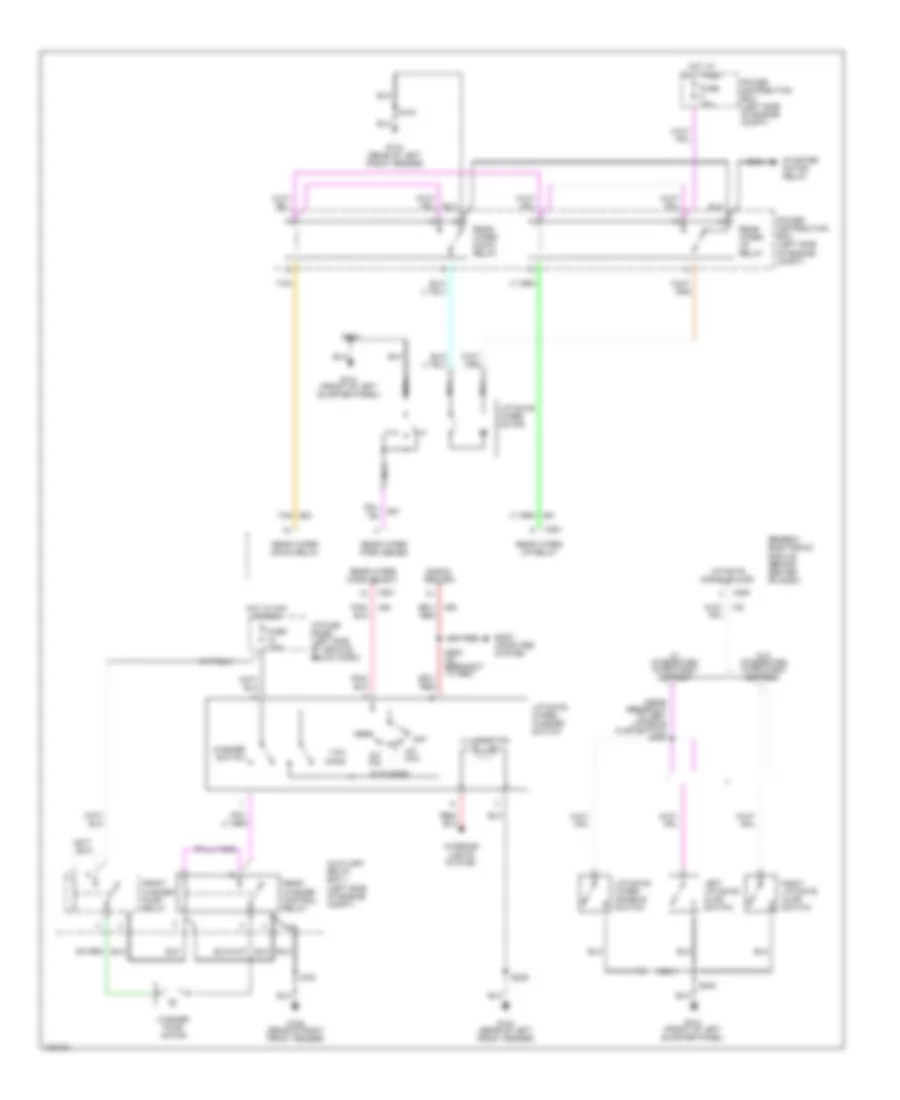 https://portal-diagnostov.com/license.html
Automotive Electricians Portal FZCO
Automotive Electricians Portal FZCO
https://portal-diagnostov.com/license.html
https://portal-diagnostov.com/license.html
Automotive Electricians Portal FZCO
Automotive Electricians Portal FZCOList of elements for Rear Wiper/Washer Wiring Diagram for Ford Explorer 1998:
- (near breakout to left liftgate ajar switch) s405
- 110k ohms
- 9.1k ohms
- Auxiliary relay box 1 (left side of engine compt)
- Body computer system
- C280
- C281
- Front washer pump relay
- Fuse 15a
- Fuse 7.5a
- G104 (rear of left front fender)
- G105 (rear of right front fender)
- G414 (front of left quarter panel)
- Generic electronic module (behind center of dash)
- Hot at all times
- Hot in acc or run
- I/p fuse panel (left side of vehicle, below dash)
- Illumination
- Int max
- Int min
- Interior lights system
- Left liftgate ajar switch
- Liftgate disable/ajar
- Liftgate wiper disable switch
- Liftgate wiper motor
- Liftgate wiper/ washer switch
- Nca
- Off
- Power distribution box (left side of engine compt)
- Rear washer control relay
- Rear wiper down relay
- Rear wiper mode select
- Rear wiper park sense
- Rear wiper up relay
- Right liftgate ajar switch
- S104
- S161
- S229
- S250 (in breakout to gem)
- S404
- Signal return
- Starter motor relay
- Tan
- W/ integrated wipe/wash/ defrost
- W/o integrated wipe/wash/ defrost
- Washer pump motor
- Washer switch

 Čeština
 Dansk
Dansk Deutsch
 Ελληνικά
 English
 English
 Español
 Suomi
Suomi Français
 Français
 עברית
עברית Hrvatski
 Magyar
 Italiano
 日本語
日本語 한국어
한국어 Nederlands
 Polski
 Português
 Português
 Română
 Русский
 Slovenčina
 Slovenščina
 Svenska
 Türkçe
