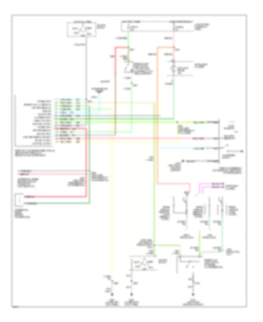
AIR CONDITIONING
A/C Wiring Diagram, Vehicles Built Before 6/24/96 for Ford Pickup F150 1997
 https://portal-diagnostov.com/license.html
Automotive Electricians Portal FZCO
Automotive Electricians Portal FZCO
https://portal-diagnostov.com/license.html
https://portal-diagnostov.com/license.html
Automotive Electricians Portal FZCO
Automotive Electricians Portal FZCO
List of elements for A/C Wiring Diagram, Vehicles Built Before 6/24/96 for Ford Pickup F150 1997:
- (engine cntrl sens harn, right rear of engine compt)
- (heater blower motor feed harn, in blower motor resistor breakout)
- (main harn, near glove compt lamp breakout)
- A/c clutch cycling pressure switch (right rear corner of engine compt)
- A/c clutch diode
- A/c compressor clutch solenoid
- A/c pressure cut off switch (right side of engine compt)
- Blend door actuator (behind center of i/p)
- Blend door potentiometer
- Blower motor
- Blower motor resistor (right side of engine compartment)
- Blower motor switch (part of function selector switch)
- Blower relay
- Blower/ flasher relay block (behind center of i/p)
- C217
- C218
- C219
- C220
- Cold
- Def
- Floor
- Flr & def
- Function selector switch
- Fuse 10a
- Fuse 15a
- Fuse 40a
- G105 (rear of right fender apron)
- G201 (behind bottom of right cowl panel)
- Hot at all times
- Hot in run
- Illum
- Interior lights system
- Junction box fuse/ relay panel
- Max a/c
- Med hi
- Med lo
- Norm a/c
- Off
- Panel
- Panel & floor
- Panel & off floor
- Power distribution box
- Powertrain control module (pcm) (right side of engine compt)
- S103 (fuel charge harn, right rear of engine compartment)
- S125
- S126
- S200
- S202 (main harn, behind center of i/p)
- S202 (main harness, behind center of i/p)
- S203 (main harness, right side of i/p)
- S222 (main harn, near i/p cluster break- out)
- Warm
A/C Wiring Diagram, Vehicles Built On or After 6/24/96 for Ford Pickup F150 1997
 https://portal-diagnostov.com/license.html
Automotive Electricians Portal FZCO
Automotive Electricians Portal FZCO
https://portal-diagnostov.com/license.html
https://portal-diagnostov.com/license.html
Automotive Electricians Portal FZCO
Automotive Electricians Portal FZCOList of elements for A/C Wiring Diagram, Vehicles Built On or After 6/24/96 for Ford Pickup F150 1997:
- (engine cntrl sens harn, right rear of engine compt)
- (heater blower motor feed harn, in blower motor resistor breakout)
- (main harn, near glove compt lamp breakout)
- A/c clutch cycling pressure switch (right rear corner of engine compt)
- A/c clutch diode
- A/c compressor clutch solenoid
- A/c pressure cut off switch (right side of engine compt)
- Blend door actuator (behind center of i/p)
- Blend door potentiometer
- Blower motor
- Blower motor resistor (right side of engine compartment)
- Blower motor switch (part of function selector switch)
- Blower relay
- Blower/ flasher relay block (behind center of i/p)
- C217
- C218
- C219
- C220
- Cold
- Def
- Floor
- Flr & def
- Function selector switch
- Fuse 10a
- Fuse 15a
- Fuse 40a
- G105 (rear of right fender apron)
- G201 (behind bottom of right cowl panel)
- Hot at all times
- Hot in run
- Illum
- Interior lights system
- Junction box fuse/ relay panel
- Max a/c
- Med hi
- Med lo
- Norm a/c
- Off
- Panel
- Panel & floor
- Panel & off floor
- Power distribution box
- Powertrain control module (pcm) (right side of engine compt)
- S103 (fuel charge harn, right rear of engine compartment)
- S125
- S126
- S200
- S202 (main harn, behind center of i/p)
- S202 (main harness, behind center of i/p)
- S203 (main harness, right side of i/p)
- S222 (main harn, near i/p cluster break- out)
- Warm
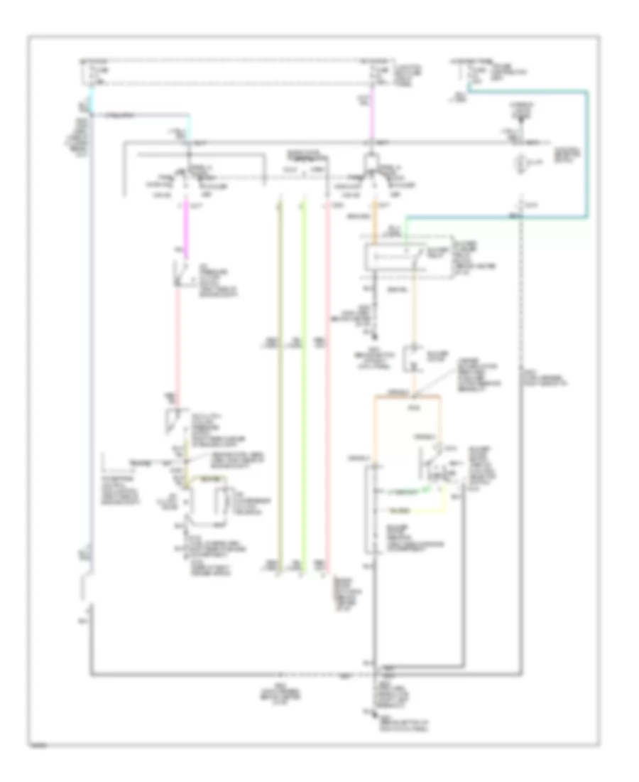
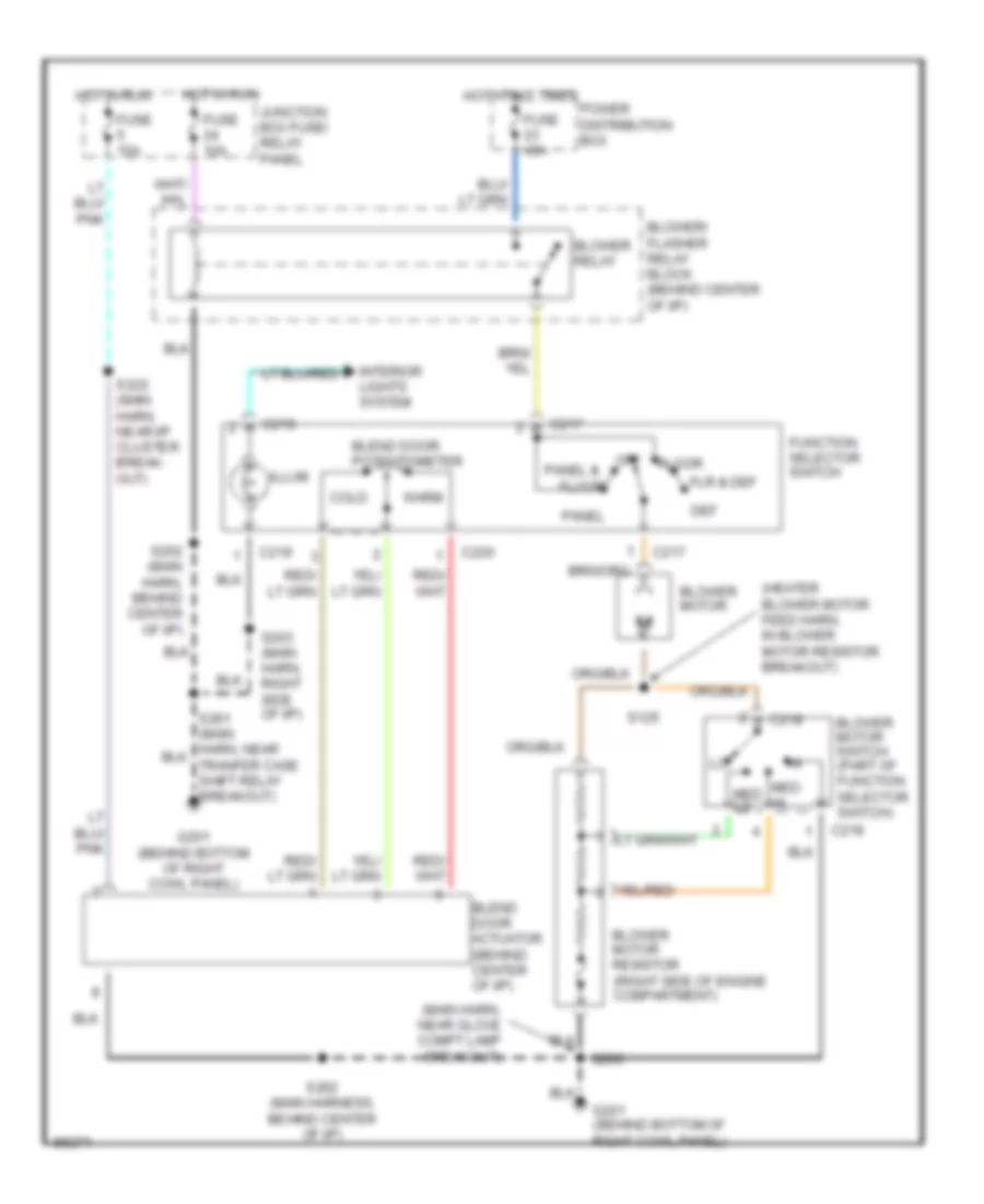
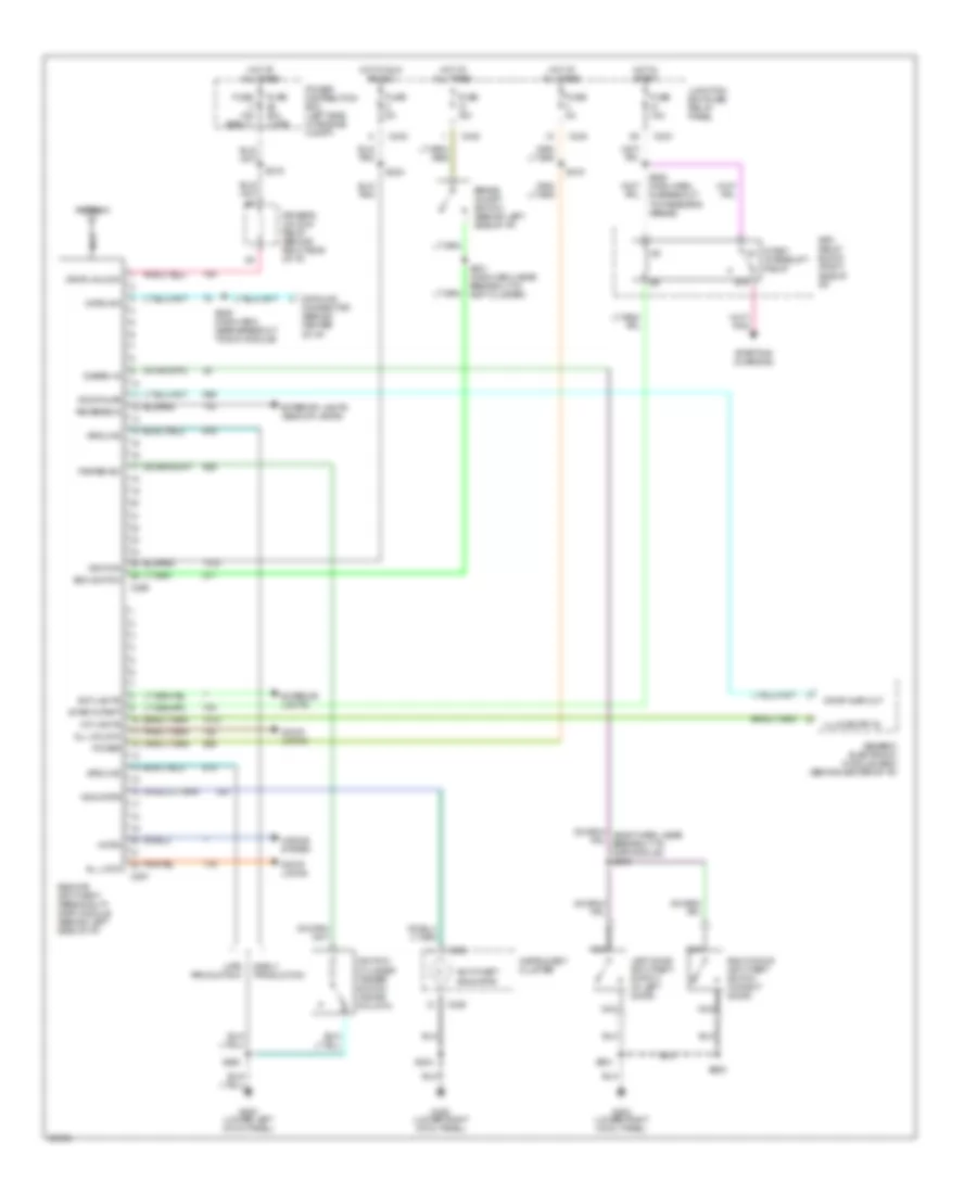
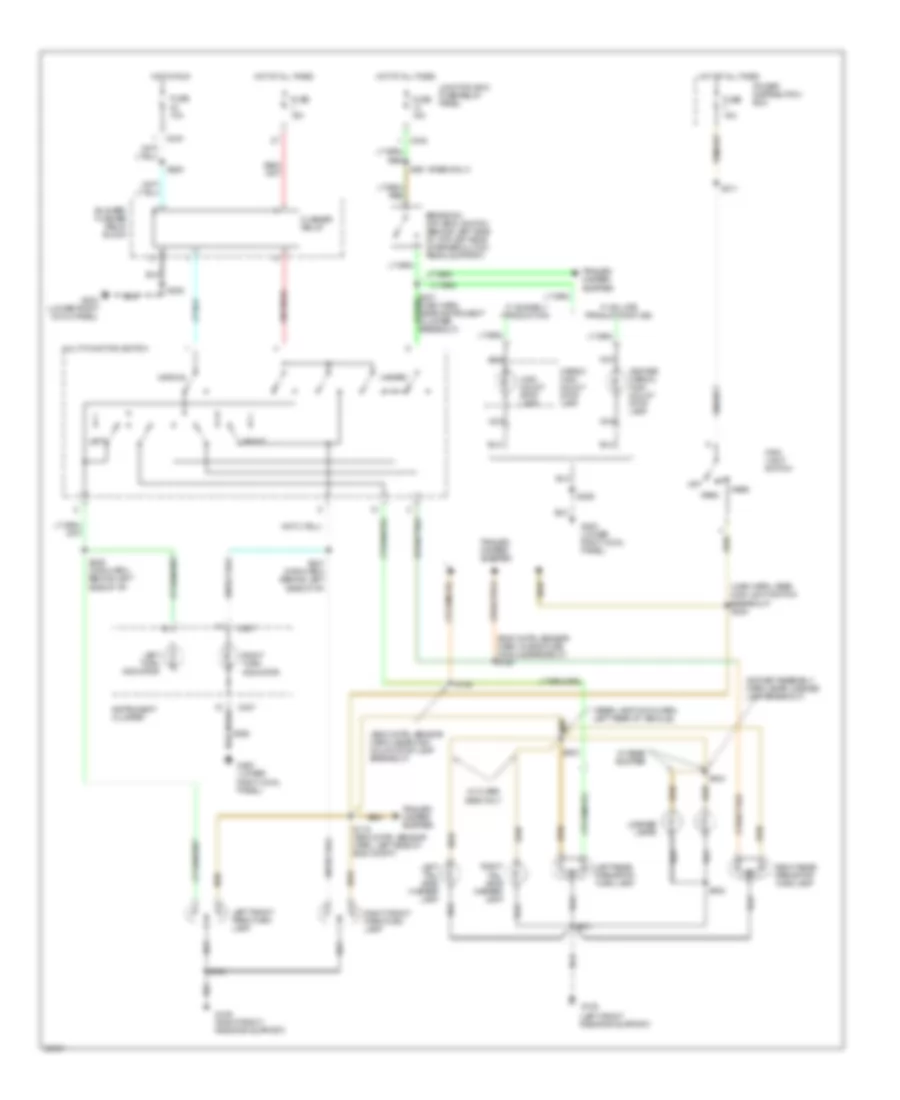
Heater Wiring Diagram, Vehicles Built Before 6/24/96 for Ford Pickup F150 1997
 https://portal-diagnostov.com/license.html
Automotive Electricians Portal FZCO
Automotive Electricians Portal FZCO
https://portal-diagnostov.com/license.html
https://portal-diagnostov.com/license.html
Automotive Electricians Portal FZCO
Automotive Electricians Portal FZCOList of elements for Heater Wiring Diagram, Vehicles Built Before 6/24/96 for Ford Pickup F150 1997:
- (heater blower motor feed harn, in blower motor resistor breakout)
- (main harn, near glove compt lamp breakout)
- Blend door actuator (behind center of i/p)
- Blend door potentiometer
- Blower motor
- Blower motor resistor (right side of engine compartment)
- Blower motor switch (part of function selector switch)
- Blower relay
- Blower/ flasher relay block (behind center of i/p)
- C217
- C218
- C219
- C220
- Cold
- Def
- Floor
- Flr & def
- Function selector switch
- Fuse 10a
- Fuse 15a
- Fuse 40a
- G201 (behind bottom of right cowl panel)
- Hot at all times
- Hot in run
- Illum
- Interior lights system
- Junction box fuse/ relay panel
- Med hi
- Med lo
- Off
- Panel
- Panel &
- Power distribution box
- S125
- S200
- S201 (main harn, near tranfer case shift relay breakout)
- S202 (main harn, behind center of i/p)
- S202 (main harness, behind center of i/p)
- S203 (main harn, right side of i/p)
- S222 (main harn, near i/p cluster break- out)
- Warm
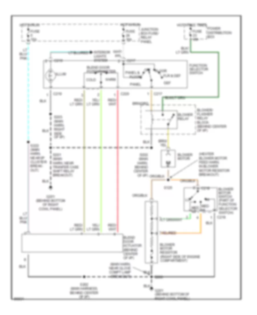
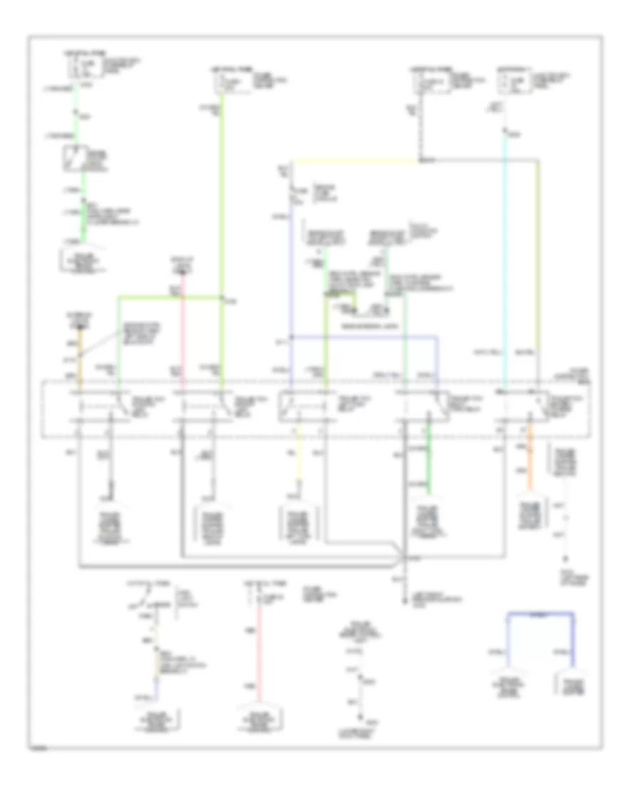
Heater Wiring Diagram, Vehicles Built On or After 6/24/96 for Ford Pickup F150 1997
 https://portal-diagnostov.com/license.html
Automotive Electricians Portal FZCO
Automotive Electricians Portal FZCO
https://portal-diagnostov.com/license.html
https://portal-diagnostov.com/license.html
Automotive Electricians Portal FZCO
Automotive Electricians Portal FZCOList of elements for Heater Wiring Diagram, Vehicles Built On or After 6/24/96 for Ford Pickup F150 1997:
- (heater blower motor feed harn, in blower motor resistor breakout)
- (main harn, near glove compt lamp breakout)
- Blend door actuator (behind center of i/p)
- Blend door potentiometer
- Blower motor
- Blower motor resistor (right side of engine compartment)
- Blower motor switch (part of function selector switch)
- Blower relay
- Blower/ flasher relay block (behind center of i/p)
- C217
- C218
- C219
- C220
- Cold
- Def
- Floor
- Flr & def
- Function selector switch
- Fuse 10a
- Fuse 15a
- Fuse 40a
- G201 (behind bottom of right cowl panel)
- Hot at all times
- Hot in run
- Illum
- Interior lights system
- Junction box fuse/ relay panel
- Med hi
- Med lo
- Off
- Panel
- Panel &
- Power distribution box
- S125
- S200
- S201 (main harn, near tranfer case shift relay breakout)
- S202 (main harness, behind center of i/p)
- S203 (main harn, right side of i/p)
- S222 (main harn, near i/p cluster break- out)
- Warm
ANTI-LOCK BRAKES
All-Wheel ABS Wiring Diagram for Ford Pickup F150 1997
 https://portal-diagnostov.com/license.html
Automotive Electricians Portal FZCO
Automotive Electricians Portal FZCO
https://portal-diagnostov.com/license.html
https://portal-diagnostov.com/license.html
Automotive Electricians Portal FZCO
Automotive Electricians Portal FZCOList of elements for All-Wheel ABS Wiring Diagram for Ford Pickup F150 1997:
- 4 wheel anti-lock brakes system (4wabs) module (left side of engine compt)
- 4 wheel drive input
- 4wabs ind ctrl
- Anti-lock brake ind
- Brake fluid level switch (on brake fluid reservoir)
- Brake fluid lvl
- Brake on/off (boo) switch (behind left side of i/p)
- Brake on/off switch
- C146
- C147
- C242
- C243
- Datalink connector (left side of i/p)
- Diagnostic trigger
- Differential speed sensor (on rear axle)
- Fuse 15a
- Fuse 5a
- Fuse 60a
- G108 (left front radiator support)
- Ground
- Hot at all times
- Hot in run
- Hot in run or start
- Ignition feed
- Instrument cluster
- Junction box fuse/relay panel
- Left front sensor (high)
- Left front sensor (low)
- Left front wheel speed sensor (at wheel)
- Power (b+)
- Power distribution box
- Rear sensor (high)
- Rear sensor (low)
- Red brake ind
- Red brake lamp relay ctrl
- Red brake warning relay
- Red lamp input
- Red/pnk
- Right front sensor (high)
- Right front sensor (low)
- Right front wheel speed sensor (at wheel)
- S106
- S121
- S144
- S144 (engine control sensor harn, left side of engine compartment)
- S225
- S229
- Tan/red
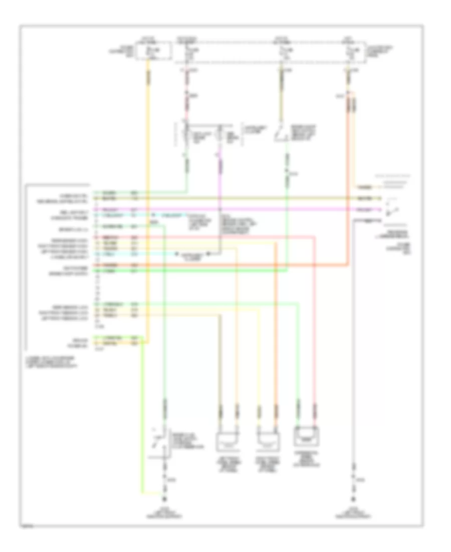
Rear Wheel ABS Wiring Diagram for Ford Pickup F150 1997
 https://portal-diagnostov.com/license.html
Automotive Electricians Portal FZCO
Automotive Electricians Portal FZCO
https://portal-diagnostov.com/license.html
https://portal-diagnostov.com/license.html
Automotive Electricians Portal FZCO
Automotive Electricians Portal FZCOList of elements for Rear Wheel ABS Wiring Diagram for Ford Pickup F150 1997:
- (main harn, left rear of engine compt) s218
- 4x4 input sig
- Acc
- Anti-lock brake ind
- Boo sw input
- Brake fluid level switch (on brake fluid reservoir)
- Brake fluid lvl sens (lo)
- Brake on/off (boo) switch (top left side of brake/clutch pedal support)
- Brake warning diode (in pdc)
- Brake warning resistor assembly (in pdc)
- Brake warning resistor/ diode assembly (in pdc)
- Diag test/keep alive input
- Diff spd sens (hi)
- Diff spd sens (lo)
- Differential speed sensor (on rear axle)
- Differential speed sensor datalink connector (left side of i/p)
- Dump sol output
- Dump solenoid
- Early production
- Fuse 13 15a
- Fuse 29 5a
- G108 (left front radiator support)
- G200 (lower left cowl panel)
- G203 (lower right cowl panel)
- Ground
- Hot at all times
- Hot in start or run
- Ignition switch
- Instrument cluster
- Iso sol output
- Isolation solenoid
- Junction box fuse/relay panel
- Late production
- Late production only
- Lock
- Nca
- Off
- Power input
- Rabs valve assembly (on frame rail, near front of transmission)
- Rear anti-lock brake (rabs) module (behind right side of i/p, behind glove compartment)
- Red
- Red/pnk
- Run
- S106
- S204
- S204 (main harn, near breakout to cluster)
- S208
- S217
- S221
- S231
- S236 (main harn, near breakout to differential)
- S237 (main harn, near breakout to differential)
- Start
- Transmissions system
- Valve reset switch
- Vlv reset input
- Warn lp output
ANTI-THEFT
Anti-theft Wiring Diagram for Ford Pickup F150 1997
 https://portal-diagnostov.com/license.html
Automotive Electricians Portal FZCO
Automotive Electricians Portal FZCO
https://portal-diagnostov.com/license.html
https://portal-diagnostov.com/license.html
Automotive Electricians Portal FZCO
Automotive Electricians Portal FZCOList of elements for Anti-theft Wiring Diagram for Ford Pickup F150 1997:
- 87a
- All lock
- All unlock
- Antenna
- Anti-theft indicator
- Boo switch
- Brake on/off switch (behind left side of i/p)
- C236
- C242
- C243
- C256
- C257
- Datalink
- Datalink connector (behind center of i/p)
- Disarm in
- Door ajar
- Door ajar out
- Door locks
- Driver's unlock relay (behind right side of i/p)
- Drvr unlock
- Early production
- Ext lights
- Exterior lights
- Exterior lights (backup lamps)
- Fuse 15a
- Fuse 15a (early)
- Fuse 20a (late)
- Fuse 5a
- G200 (lower left cowl panel)
- G203 (lower right cowl panel)
- Generic electronic module (gem) (behind center of i/p)
- Ground
- Horn
- Horns system
- Hot at all times
- Hot in run ar acc
- Hot in start
- Ignition
- Ignition cylinder tamper switch (inside column)
- Illum entry in
- Indicator
- Instrument cluster
- Int lights
- Interrupt relay
- Junction box fuse/ relay panel
- Late production
- Left door anti-theft switch (in left door)
- Nca
- Power
- Power distribution box (left side of engine compt)
- Remote anti-theft personality (rap) module (behind left side of i/p)
- Reverse in
- Right door anti-theft switch (in right door)
- Rpo relay block (right side of i/p)
- S204
- S208
- S216
- S219
- S223
- S226 (main harn, in breakout to passngr's airbag)
- S229 (main harn, near breakout to evo module)
- S231 (main harn, near breakout to inst cluster)
- S501
- S600
- Start
- Start intrpt
- Starting/ charging
- Tamper sw
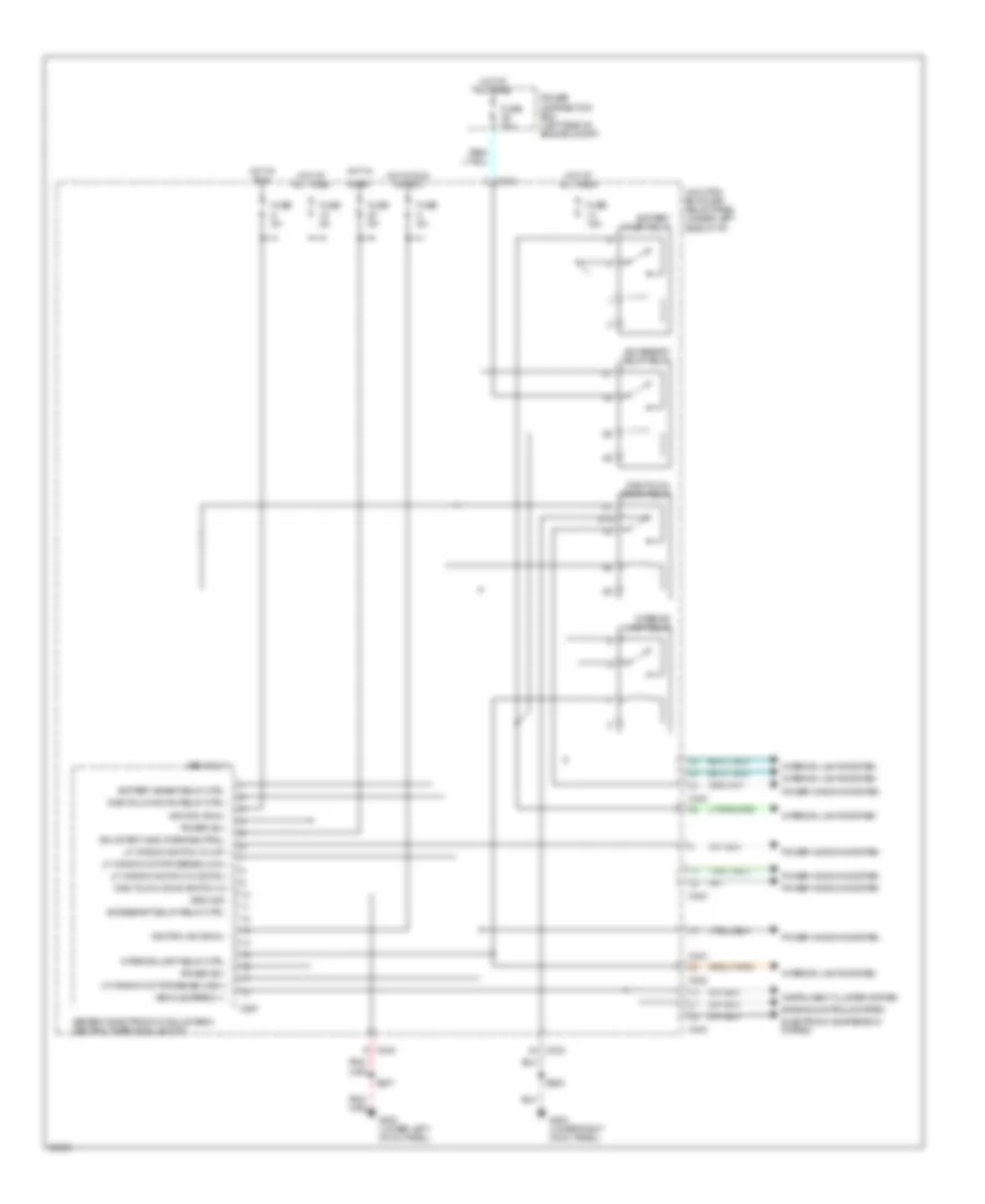
BODY COMPUTER
Body Computer Wiring Diagrams (1 of 2) for Ford Pickup F150 1997
 https://portal-diagnostov.com/license.html
Automotive Electricians Portal FZCO
Automotive Electricians Portal FZCO
https://portal-diagnostov.com/license.html
https://portal-diagnostov.com/license.html
Automotive Electricians Portal FZCO
Automotive Electricians Portal FZCOList of elements for Body Computer Wiring Diagrams (1 of 2) for Ford Pickup F150 1997:
- 87a
- Accessory delay relay
- Accessory delay relay ctrl
- Battery saver relay
- Battery saver relay ctrl
- C242
- C243
- C267
- Electronic suspension system
- Engine controls system
- Fuse 15a
- Fuse 30a
- Fuse 5a
- G200 (lower left cowl panel)
- G203 (lower right cowl panel)
- Gem only *
- Generic electronic module (gem)/ central timer module (ctm)
- Ground
- Hot at all times
- Hot in
- Hot in run
- Hot in run or acc
- Ign (start) gnd (park/neutral)
- Ignition (acc/run)
- Ignition (run)
- Instrument cluster system
- Interior lamp relay
- Interior lamp relay ctrl
- Interior lights system
- Junction box fuse/ relay panel (under left side of i/p)
- Lf window motor sense (high) *
- Lf window motor sense (low) *
- Lf window switch in (down) *
- Lf window switch in (up) *
- One touch down relay
- One touch down relay ctrl *
- One touch down switch in *
- Power (b+)
- Power distribution box (left side of engine compt)
- Power windows system
- S205
- S207
- Start
- Vehicle speed (+)
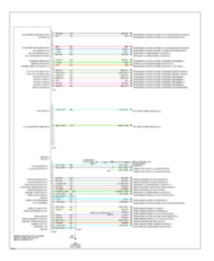
Body Computer Wiring Diagrams (2 of 2) for Ford Pickup F150 1997
 https://portal-diagnostov.com/license.html
Automotive Electricians Portal FZCO
Automotive Electricians Portal FZCO
https://portal-diagnostov.com/license.html
https://portal-diagnostov.com/license.html
Automotive Electricians Portal FZCO
Automotive Electricians Portal FZCOList of elements for Body Computer Wiring Diagrams (2 of 2) for Ford Pickup F150 1997:
- (behind center of i/p) ctm diagnostic connector
- (lower right cowl panel) g203
- (near 4wd mode switch) s238
- (park/headlamps on) in
- 4 high to 4 low relay ctrl
- 4 low to 4 high relay ctrl
- 4x2 center axle solenoid ctrl
- 4x4 center axle solenoid ctrl
- 4x4 high range ind ctrl
- 4x4 low range in
- 4x4 low range ind control
- 4x4 mode switch in
- 4x4 switch in
- Anti-theft system (rap module)
- Brake on/off switch
- C239
- C240
- C241
- Computer data lines system (datalink pin 7)
- Contact plate a in
- Contact plate b in
- Contact plate c in
- Contact plate d in
- Ctm diagnostic in
- Diagnostic link
- Door ajar indicator ctrl
- Door ajar out
- Exterior lights system (brake on/off switch)
- G200 (lower left cowl panel)
- Gem only * ctm only **
- Generic electronic module (gem)/ central timer module (ctm) (behind center of i/p)
- Ground
- Ignition key warning switch in
- Illum entry switch in
- Illuminated entry request in
- Instrument cluster system (i/c c236 pin 3)
- Instrument cluster system (i/c c236 pin 4)
- Instrument cluster system (i/c c238 pin 11)
- Instrument cluster system (i/c c238 pin 9)
- Interior lights (left illum entry switch)
- Interior lights (right illum entry switch)
- Interval delay/wash in
- Lf door ajar switch in
- Red
- Rf door ajar switch in
- S203
- S208
- S241
- Seat belt indicator ctrl
- Seat belt warning switch in
- Signal return
- Tan/red
- Trans in neutral in
- Transfer case return
- Transmission controls system (4 wheel drive mode switch)
- Transmission controls system (4wd mode switch)
- Transmission controls system (4x2 axle disconnect solenoid)
- Transmission controls system (4x4 axle disconnect solenoid)
- Transmission controls system (4x4 low indicator switch)
- Transmission controls system (electric clutch relay)
- Transmission controls system (transfer case assembly)
- Transmission controls system (transfer case shift relays)
- Transmission controls system (transmission range sensor)
- Trnsfer case clutch relay out
- Warning systems (ignition key warning switch)
- Warning systems (lf door ajar switch)
- Warning systems (main light switch)
- Warning systems (rf door ajar switch)
- Warning systems (seat belt switch)
- Washer pump ctrl
- Wiper hi/lo relay ctrl
- Wiper mode select switch in
- Wiper motor park sense
- Wiper run/park relay ctrl
- Wiper/washer system (hi/lo relay)
- Wiper/washer system (multi-function switch)
- Wiper/washer system (run/park relay)
- Wiper/washer system (washer pump relay)
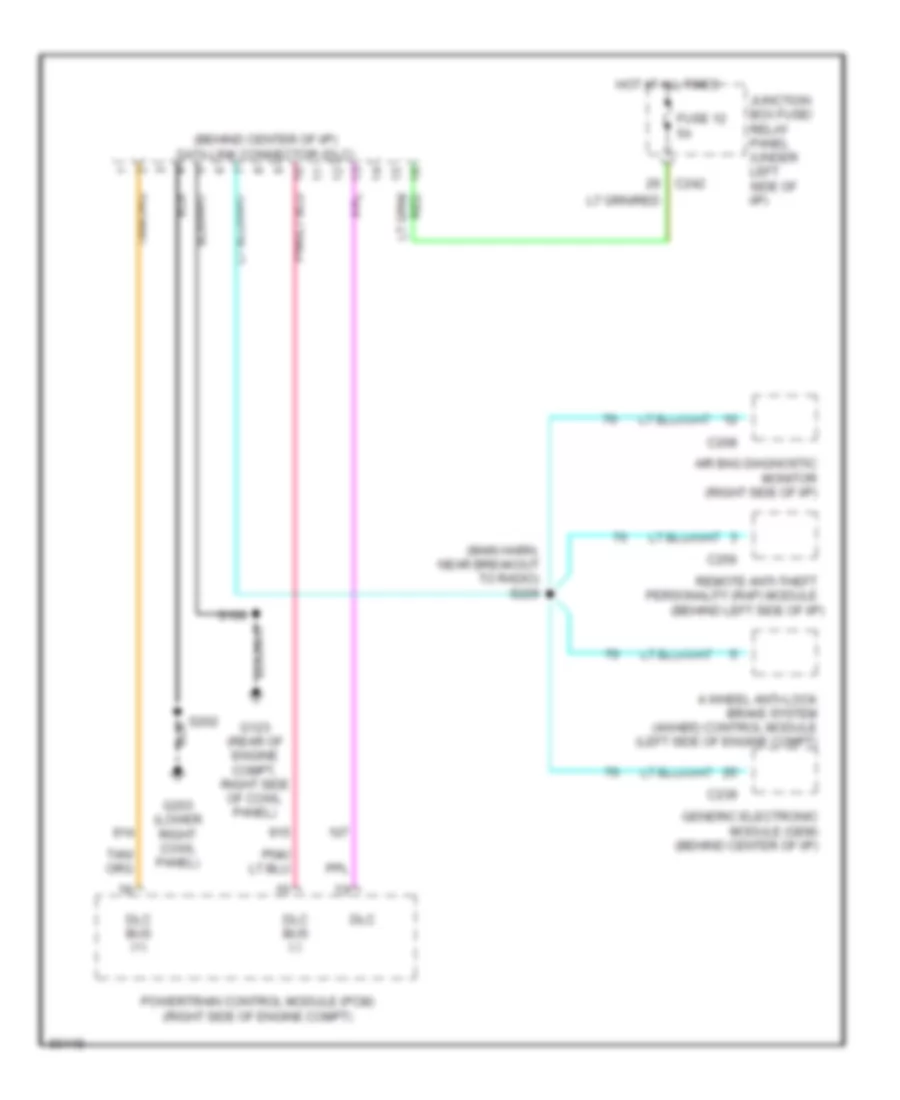
COMPUTER DATA LINES
Computer Data Lines for Ford Pickup F150 1997
 https://portal-diagnostov.com/license.html
Automotive Electricians Portal FZCO
Automotive Electricians Portal FZCO
https://portal-diagnostov.com/license.html
https://portal-diagnostov.com/license.html
Automotive Electricians Portal FZCO
Automotive Electricians Portal FZCOList of elements for Computer Data Lines for Ford Pickup F150 1997:
- (behind center of i/p) data link connector (dlc)
- (behind left side of i/p)
- (main harn, near breakout to radio) s229
- 4 wheel anti-lock brake system (4wabs) control module (left side of engine compt)
- Air bag diagnostic monitor (right side of i/p)
- C208
- C239
- C242
- C256
- Dlc
- Dlc bus (+)
- Dlc bus (-)
- Fuse 12 5a
- G123 (rear of engine compt, right side of cowl panel)
- G203 (lower right cowl panel)
- Generic electronic module (gem) (behind center of i/p)
- Hot at all times
- Junction box fuse/ relay panel (under left side of i/p)
- Powertrain control module (pcm) (right side of engine compt)
- Remote anti-theft personality (rap) module
- S100
- S202
CRUISE CONTROL
Cruise Control Wiring Diagram for Ford Pickup F150 1997
 https://portal-diagnostov.com/license.html
Automotive Electricians Portal FZCO
Automotive Electricians Portal FZCO
https://portal-diagnostov.com/license.html
https://portal-diagnostov.com/license.html
Automotive Electricians Portal FZCO
Automotive Electricians Portal FZCOList of elements for Cruise Control Wiring Diagram for Ford Pickup F150 1997:
- (main harn, near breakout to clockspring assembly) s230
- (main harn, near breakout to instrument cluster) s231
- 15a
- 20a
- A/t
- Accel
- Brake on/off (boo) switch (behind left side of i/p)
- Brake press in
- Brake pressure switch (left rear corner of engine compt)
- C233
- C234
- C239
- C242
- C257
- Clock- spring assembly (top of steering column)
- Clutch pedal position (ccp) switch (on clutch pedal arm)
- Clutch pedal position (ccp) switch jumper (left side of i/p)
- Coast
- Control sw gnd
- Control sw in
- Driver's airbag
- Fuse 13
- Fuse 5
- G105 (rear of right fender apron)
- G200 (lower left cowl panel)
- G203 (lower right cowl panel)
- Generic electronic module (gem)/ central timer module (ctm) (behind center of i/p)
- Ground
- Horn relay (in power distribution box)
- Horn switches
- Hot at all times
- Hot in run
- Hrn rly
- Ign
- Ignition key warning switch
- Interior lights system
- Junction box fuse/relay panel
- M/t
- Nca
- Off
- Ohms
- Power distri- bution box
- Remote anti-theft personality (rap) module (behind left side of i/p)
- Resume
- S102
- S107
- S112
- S143 (engine sensor harn, near breakout to vapor management valve)
- S221
- Set/
- Speed control servo/ amplifier assembly (left side of engine compt)
- Speed control switch assembly
- Steering column assembly
- Steering column ground
- Vehicle speed input
- Vehicle speed sensor (vss) (left rear of trans)
ELECTRONIC SUSPENSION
Electronic Suspension Wiring Diagram for Ford Pickup F150 1997
 https://portal-diagnostov.com/license.html
Automotive Electricians Portal FZCO
Automotive Electricians Portal FZCO
https://portal-diagnostov.com/license.html
https://portal-diagnostov.com/license.html
Automotive Electricians Portal FZCO
Automotive Electricians Portal FZCOList of elements for Electronic Suspension Wiring Diagram for Ford Pickup F150 1997:
- (main harn, near ras module) s295
- Air suspension switch (behind right side of i/p1)
- Body computer
- C237
- C242
- C276
- C277
- Check suspension indicator
- Comp relay ctrl
- Connector (behind right side of i/p)
- Datalink
- Engine compartment fuse/relay box
- Engine controls
- Fuse 15a
- Fuse 50a
- Fuse 5a
- G108 (left front radiator support)
- G109 (right front radiator support
- G200 (lower left cowl panel)
- G203 (lower right cowl panel)
- Ground
- Hot at all times
- Hot in run
- Instrument cluster
- Junction box fuse/ relay panel
- Left air spring solenoid (left rear of vehicle, on air spring)
- Left rear height sensor (left rear wheel well)
- Lft height in (high)
- Lft height in (low)
- Lft spring ctrl
- Nca
- Not used
- Pnk
- Power (bat)
- Power (run)
- Power distribution box
- Rear air suspension (ras) module (behind center of i/p)
- Rear air suspension compressor motor and vent soenoid (right front of engine compt)
- Rear air suspension compressor relay
- Rear air suspension datalink
- Red
- Rht height in (high)
- Rht height in (low)
- Rht spring ctrl
- Right air spring solenoid (right rear of vehicle, on air spring)
- Right rear height sensor (right rear wheel well)
- S105
- S152
- S207
- S265
- S294 (main harn, near breakout to airbag diag monitor)
- S409 (rear lamp harn, near breakout to fuel pump module)
- S410
- S410 (rear lamp harn, near breakout to fuel pump module)
- S411
- Sensor ground
- Sensor power
- Service sw in
- Vent solenoid ctrl
- Warning lamp
ENGINE PERFORMANCE
4.2L
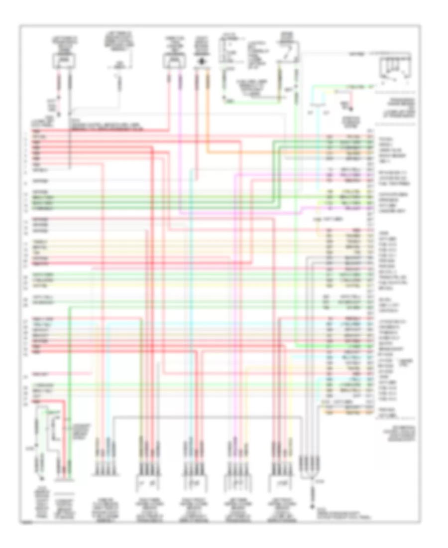
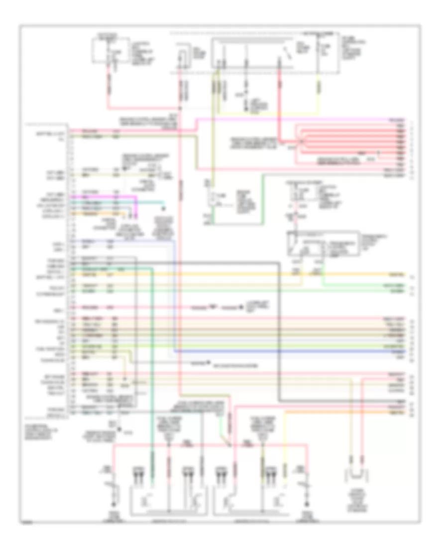
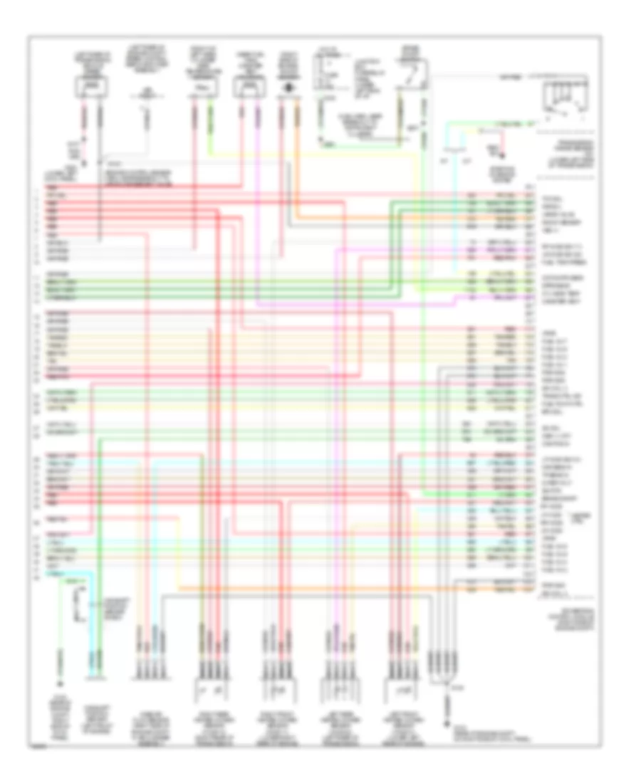
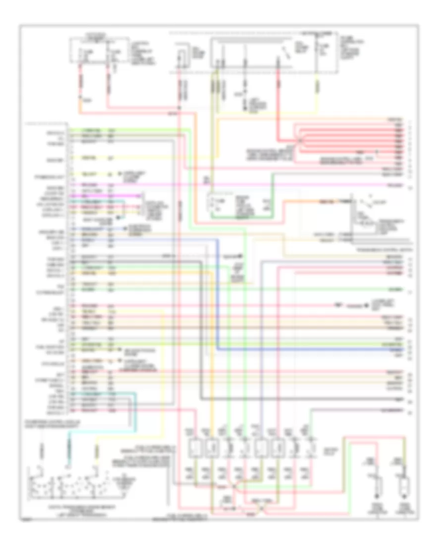
4.2L, Engine Performance Wiring Diagrams, Early Production (1 of 4) for Ford Pickup F150 1997
 https://portal-diagnostov.com/license.html
Automotive Electricians Portal FZCO
Automotive Electricians Portal FZCO
https://portal-diagnostov.com/license.html
https://portal-diagnostov.com/license.html
Automotive Electricians Portal FZCO
Automotive Electricians Portal FZCOList of elements for 4.2L, Engine Performance Wiring Diagrams, Early Production (1 of 4) for Ford Pickup F150 1997:
- (engine control harn, near breakout to pcm)
- (engine control sensor harn, near breakout to g123)
- (engine control sensor harn, near breakout to g123) s134
- (engine control sensor harn, near breakout to vapor management valve)
- (fuel charge harn, in breakout to intake runner control monitor)
- (fuel charge harn, near breakout to radio noise capacitor)
- (left radiator support) g108
- (lower left cowl panel) g201
- (partial 16-pin connector)
- 4x4 hi/low indicator switch & generic electronic module
- 4x4 low ind sw
- 820 ohms
- Accs
- Air conditioning system
- C243
- Case gnd
- Ckp(+)
- Ckp(-)
- Data link (+)
- Data link (-)
- Data link connector (below center of i/p)
- Ect
- Ect gauge
- Engine fuse module (left side of engine compt)
- Evr ctrl
- Feps (eprom)
- Fuel pump mon
- Fuse 30a
- Fuse 5a
- G105 (rear of right fender apron)
- G123 (rear of engine compt, right side of cowl panel)
- Hot at all times
- Hot in run or start
- Iat
- Ign coil 1
- Ign coil 2
- Ignition coil (top of engine)
- Imrc 1
- Imrc 2
- Intake manifold runner control (top front of engine)
- Intake manifold runner control monitor 1 (rear of engine)
- Intake manifold runner control monitor 2 (right side of engine)
- Junction box fuse/relay panel (under left side of i/p)
- Maf
- Mil
- Nca
- Not used
- O/d off
- Octane adjust
- Pcm power diode
- Pcm power relay
- Power distribution box (left side of engine compt)
- Powertrain control module (right side of engine compt)
- Pwr gnd
- Radio noise capacitor
- Red
- Red/ s225
- Rr ho2s sig (12)
- S100
- S103
- S106
- S107
- S116 (engine control sensor harn, near breakout to engine fuse module)
- S117
- S127
- S128
- S130
- S132
- S133
- Shift sol 1 (a/t)
- Shift sol 2 (a/t)
- Spark plugs
- Tach out
- Tcs (a/t)
- Tft
- Transmission control indicator lamp
- Transmission control switch (a/t)
- Tuning valve
- Vss (-)
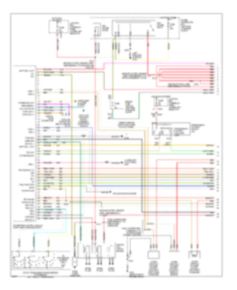
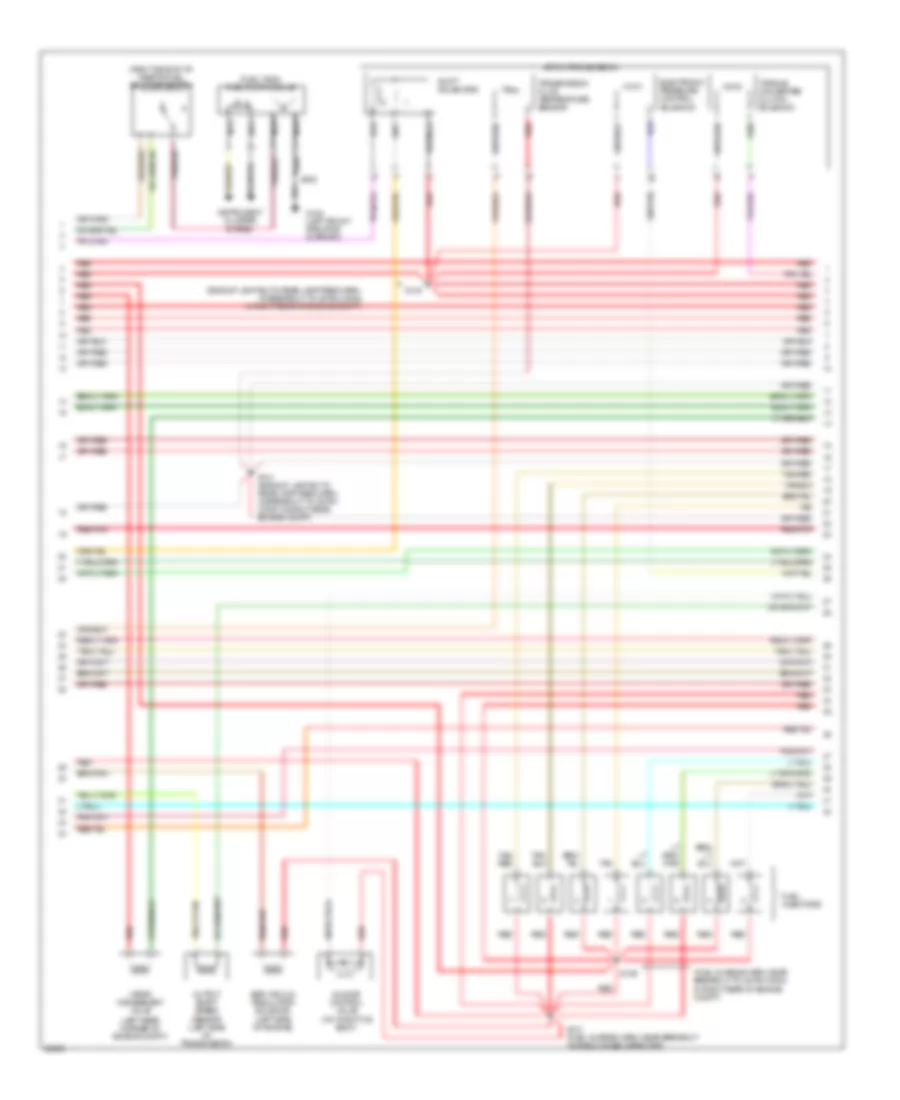
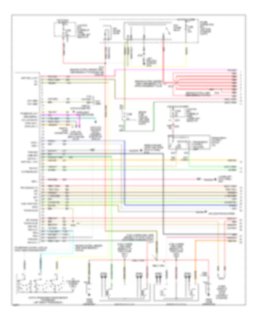
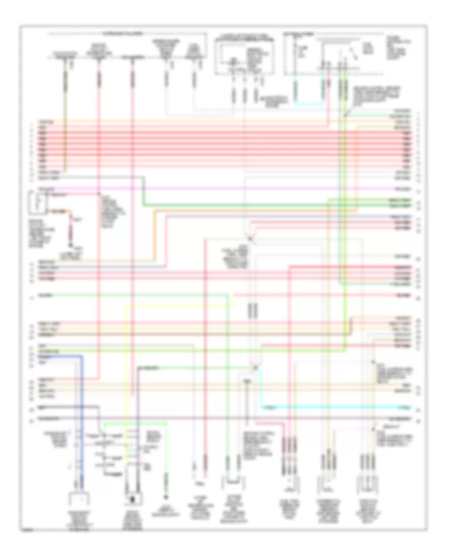
4.2L, Engine Performance Wiring Diagrams, Early Production (2 of 4) for Ford Pickup F150 1997
 https://portal-diagnostov.com/license.html
Automotive Electricians Portal FZCO
Automotive Electricians Portal FZCO
https://portal-diagnostov.com/license.html
https://portal-diagnostov.com/license.html
Automotive Electricians Portal FZCO
Automotive Electricians Portal FZCOList of elements for 4.2L, Engine Performance Wiring Diagrams, Early Production (2 of 4) for Ford Pickup F150 1997:
- (engine control sensor harn, near breakout to 35-pin conn in left rear of engine compt) s139
- (engine control sensor harn, near breakout to 38-pin conn in right rear of engine compt)
- (not used)
- (speedometer/ odometer) vehicle speed input
- (under left side of i/p) junction box fuse/relay panel
- C120
- C236
- C237
- C243
- C267
- Crankshaft position sensor (lower front of engine)
- Crankshaft position sensor shield
- Differential pressure feedback egr sensor (right side of engine)
- Electronic suspension system
- Engine coolant temperature gauge
- Engine coolant temperature sensor (front of engine)
- Fuel pump relay
- Fuel reset switch indicator
- Fuel tank pressure sensor (at fuel tank)
- Fuse 20a
- G123 (rear of engine compt, right side of cowl panel)
- Generic electronic module/ central timer module
- Hot at all times
- Instrument cluster
- Intake air temperature sensor (on intake manifold)
- Malfunction indicator
- Nca
- Octane adjust shorting bar (right rear corner of engine compt)
- Power distribution box (left side of engine compt)
- Red
- Red/pnk
- S101 (engine control harn, in breakout to pcm)
- S123 (engine control harn, near breakout to starter motor relay)
- S135 (fuel charge harn, near breakout to radio noise capacitor)
- S136 (fuel charge harn, near breakout to fuel injector 3)
- S137 (fuel charge harn, near breakout to starter motor relay)
- S138
- Tachometer
- Throttle position sensor (attached to throttle body)
- Vss input
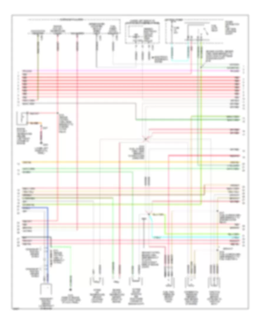
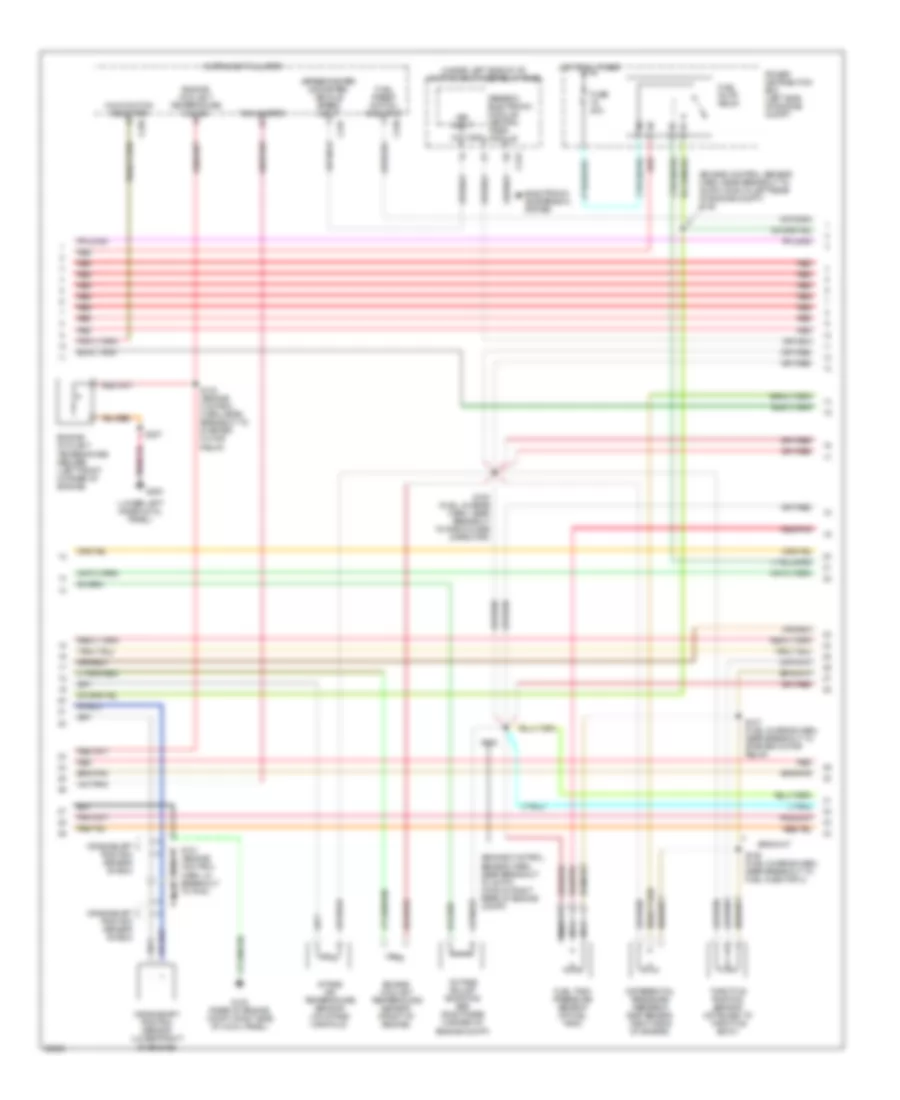
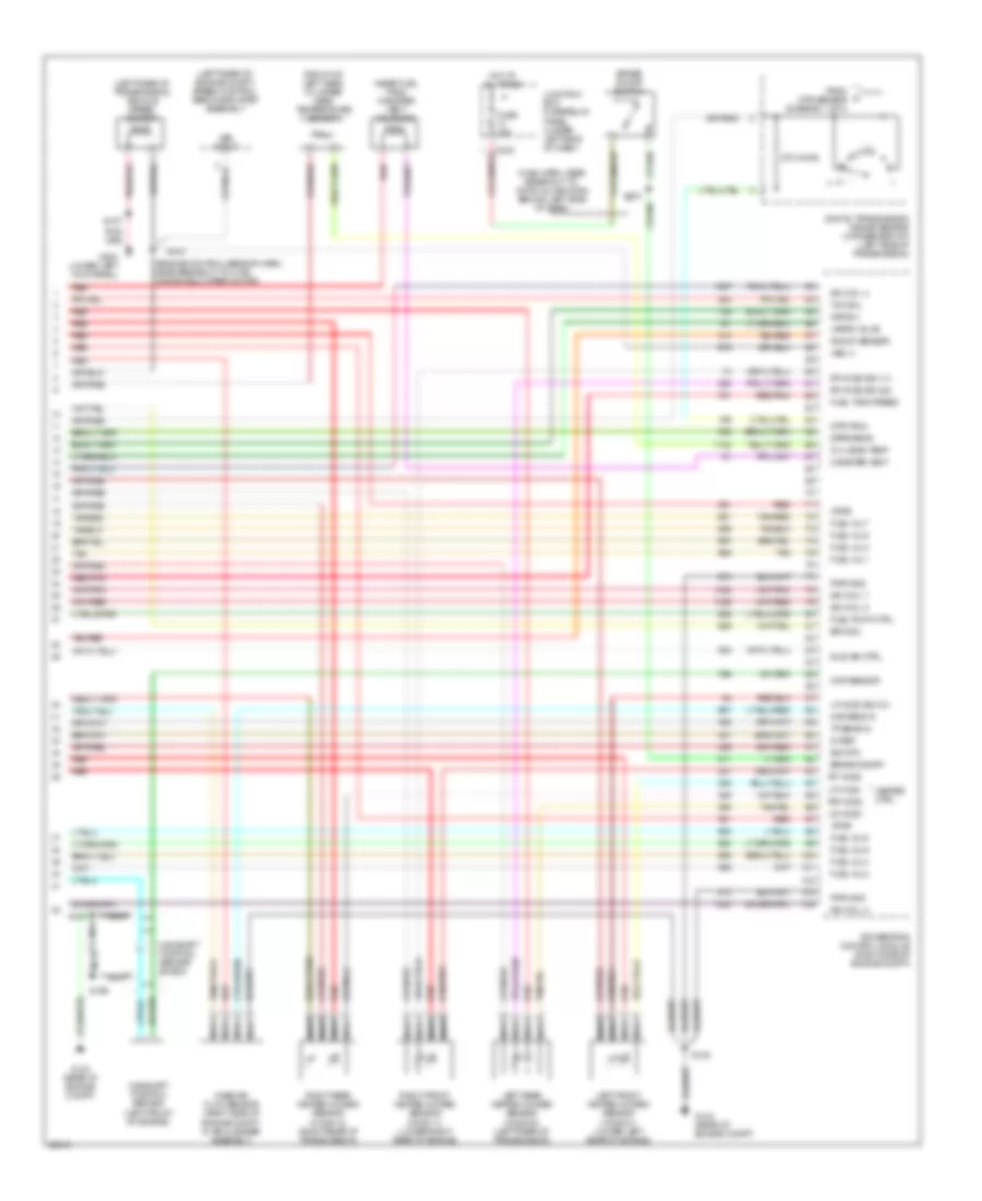
4.2L, Engine Performance Wiring Diagrams, Early Production (3 of 4) for Ford Pickup F150 1997
 https://portal-diagnostov.com/license.html
Automotive Electricians Portal FZCO
Automotive Electricians Portal FZCO
https://portal-diagnostov.com/license.html
https://portal-diagnostov.com/license.html
Automotive Electricians Portal FZCO
Automotive Electricians Portal FZCOList of elements for 4.2L, Engine Performance Wiring Diagrams, Early Production (3 of 4) for Ford Pickup F150 1997:
- (backup lamp sw to rear lamp feed harn, at breakout to 38-pin conn in right rear of engine compt)
- (fuel charge harn, near breakout to 42-pin conn (c120) in right rear of engine compt)
- (fuel tank) fuel pump module
- (left rear corner of engine compt)
- (right side of i/p) inertia fuel shut-off switch
- 4r70w transmission
- Egr vacuum regulator solenoid (left side of engine)
- Electronic pressure control solenoid
- Fuel injectors
- G108 (left front radiator support)
- Idle air control valve (on throttle body)
- Instrument cluster system
- Nca
- Output shaft speed sensor (left side of transmission)
- Red
- Red/pnk
- S129
- S131 (fuel charge harn, near breakout to radio noise capacitor)
- S140
- S141 (backup lamp sw to rear lamp feed harn, in breakout to 38-pin conn in right rear engine compt)
- S400
- Shift solenoids
- Tan
- Torque converter clutch solenoid
- Transmission fluid temperature sensor
- Vapor management valve
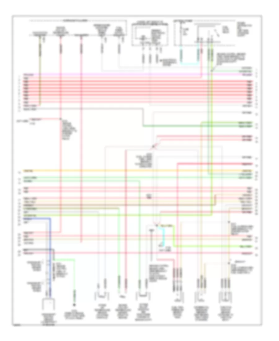
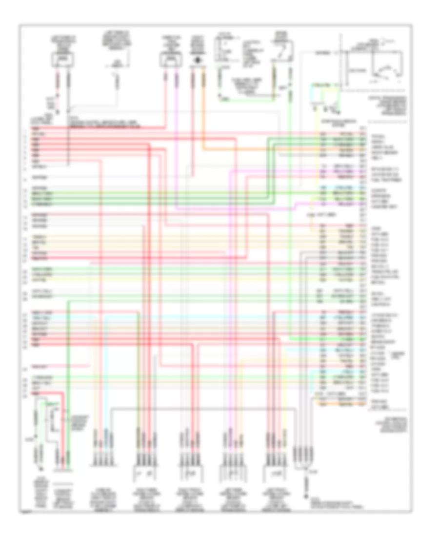
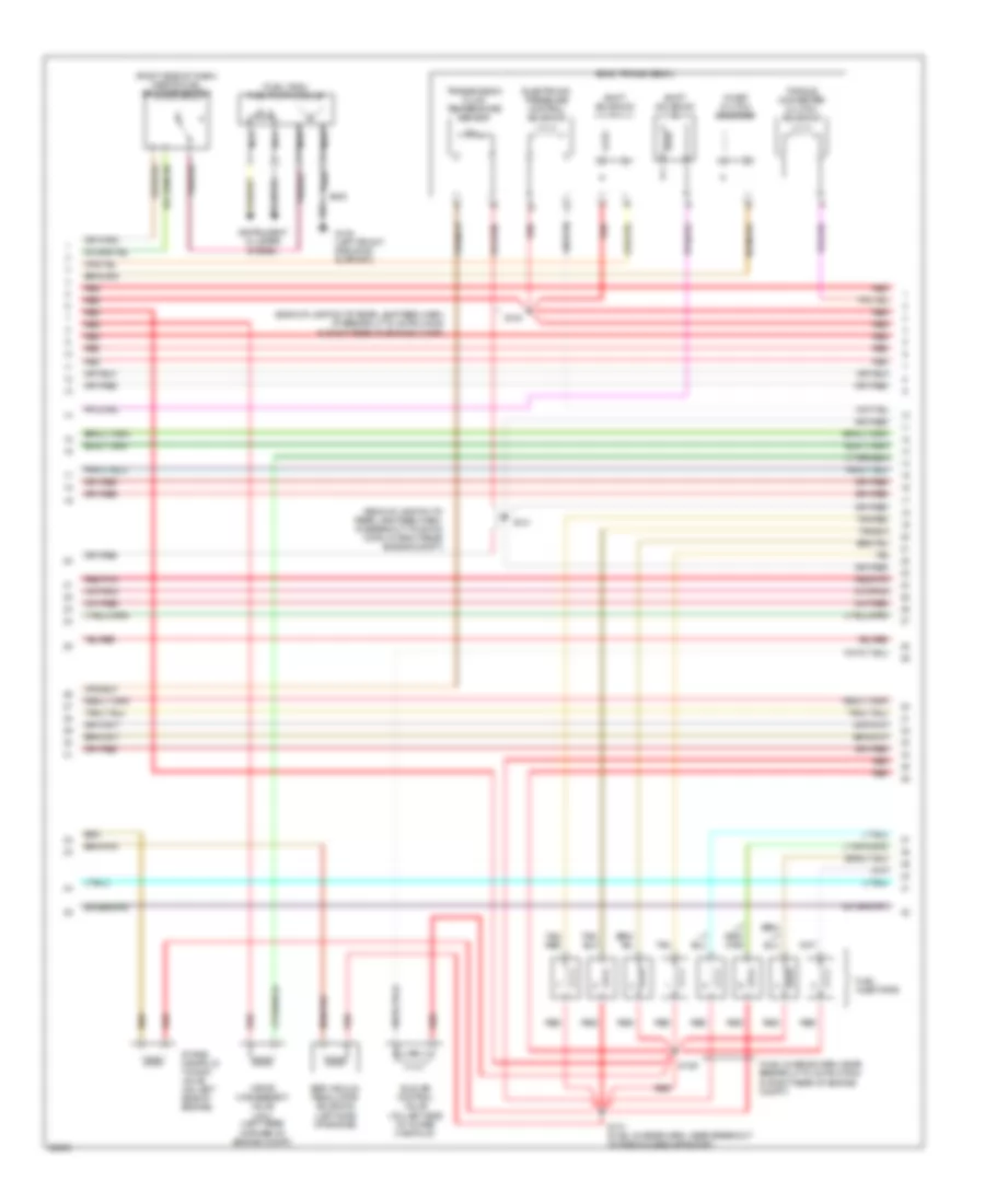
4.2L, Engine Performance Wiring Diagrams, Early Production (4 of 4) for Ford Pickup F150 1997
 https://portal-diagnostov.com/license.html
Automotive Electricians Portal FZCO
Automotive Electricians Portal FZCO
https://portal-diagnostov.com/license.html
https://portal-diagnostov.com/license.html
Automotive Electricians Portal FZCO
Automotive Electricians Portal FZCOList of elements for 4.2L, Engine Performance Wiring Diagrams, Early Production (4 of 4) for Ford Pickup F150 1997:
- (left rear of engine compt) speed control servo/amplifier assembly
- (left rear of transmission) vehicle speed sensor
- (main harn, near breakout to instrument cluster)
- (near fuel tank) canister vent solenoid
- (not used)
- (right side of engine) knock sensor
- 5v ref volt
- A/t
- Brake on/off
- Brake on/off switch
- C120
- C242
- Cam pos in
- Camshaft position sensor (left front of engine)
- Camshaft position sensor shield
- Canister vent
- Ccp sw/tr sens
- Dpfe sens
- Epc sol
- Fuel inj 1
- Fuel inj 2
- Fuel inj 3
- Fuel inj 4
- Fuel inj 5
- Fuel inj 6
- Fuel pump ctrl
- Fuel tank press
- Fuse 15a
- G123 (rear of engine compt, on right side of cowl panel)
- G123 (rear of engine compt, right side of cowl panel)
- G200 (lower left cowl panel)
- Heater ctrl
- Hot at all times
- Iac sol
- Ign coil 3
- Junction box fuse/relay panel (under left side of i/p)
- Kap b(+)
- Knock sensor
- Left front heated oxygen sensor (ho2s 21) (lower left rear of engine)
- Left rear heated oxygen sensor (ho2s 22) (left rear of transmission)
- Lf ho2s
- Lf ho2s sig (21)
- Lr ho2s
- Lr ho2s sig (22)
- M/t
- Maf sens in
- Mass air flow sensor (right side of engine compt, in air cleaner assembly)
- Nca
- Not used
- Oss (+) (a/t)
- Powertrain control module (right side of engine compt)
- Pwr gnd
- Red
- Red/pnk
- Rf ho2s
- Rf ho2s sig (11)
- Right front heated oxygen sensor (ho2s 11) (lower right rear of engine)
- Right rear heated oxygen sensor (ho2s 12) (right rear of transmission)
- Rr ho2s
- S100
- S101
- S107
- S143 (engine control sensor harn, near breakout to vapor management valve)
- S221
- S231
- Sig rtn
- Starting/ charging system
- Tan
- Tan/red
- Tcc sol
- Tp sens in
- Trans ctrl ind
- Transmission range sensor (a/t) (lower left side of transmission)
- Vapor valve
- Vpwr
- Vss (+)
- Vss input
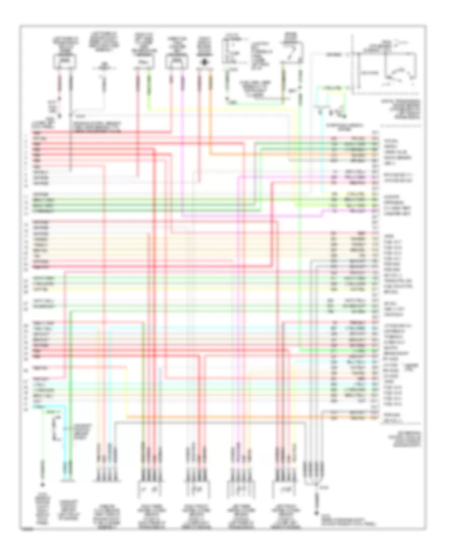
4.2L, Engine Performance Wiring Diagrams, Late Production (1 of 4) for Ford Pickup F150 1997
 https://portal-diagnostov.com/license.html
Automotive Electricians Portal FZCO
Automotive Electricians Portal FZCO
https://portal-diagnostov.com/license.html
https://portal-diagnostov.com/license.html
Automotive Electricians Portal FZCO
Automotive Electricians Portal FZCOList of elements for 4.2L, Engine Performance Wiring Diagrams, Late Production (1 of 4) for Ford Pickup F150 1997:
- (engine control harn, near breakout to pcm)
- (engine control sensor
- (engine control sensor harn, near breakout to vapor management valve)
- (fuel charge harn, in breakout to intake runner control monitor)
- (fuel charge harn, near breakout to radio noise capacitor)
- (left radiator support) g108
- (lower left cowl panel) g201
- (partial: 16-pin connector)
- (rear of engine compt, right side of cowl panel)
- 4x4 hi/low indicator switch & generic electronic module
- 4x4 low ind sw
- 820 ohms
- Accs
- Air conditioning system
- C243
- Case gnd
- Ckp(+)
- Ckp(-)
- Data link (+)
- Data link (-)
- Data link connector (below center of i/p)
- Digital transmission range sensor (dtr sensor) (left side of transmission)
- Ect
- Ect gauge
- Engine fuse module (left side of engine compt)
- Evr ctrl
- Feps (eprom)
- Fp sending unit
- Fuel pump mon
- Fuse 30a
- Fuse 5a
- G105 (rear of right fender apron)
- G123
- Harn, near breakout to g123)
- Hot at all times
- Hot in run or start
- Iat
- Ign coil 1
- Ign coil 2
- Ignition coil (top of engine)
- Imrc 1
- Imrc 2
- Instrument cluster system
- Intake manifold runner control (top front of engine)
- Intake manifold runner control monitor 1 (rear of engine)
- Intake manifold runner control monitor 2 (right side of engine)
- Junction box fuse/relay panel (under left side of i/p)
- Maf
- Mil
- Nca
- O/d off
- Octane adjust
- Pcm power diode
- Pcm power relay
- Power distribution box (left side of engine compt)
- Powertrain control module (right side of engine compt)
- Pwr gnd
- R n
- Radio noise capacitor
- Red
- Red/ s225
- Rr ho2s sig (12)
- S100
- S103
- S106
- S107
- S116 (engine control sensor harn, near breakout to engine fuse module)
- S117
- S127
- S128
- S130
- S132
- S133
- Shift sol 1 (a/t)
- Shift sol 2 (a/t)
- Spark plugs
- Tach out
- Tcs (a/t)
- Tft
- To dtr sensor (diagram 4 of 4)
- Tr1
- Tr2a
- Tr4a
- Transmission control indicator lamp
- Transmission control switch (a/t)
- Tuning valve
- Vss (-)
4.2L, Engine Performance Wiring Diagrams, Late Production (2 of 4) for Ford Pickup F150 1997
 https://portal-diagnostov.com/license.html
Automotive Electricians Portal FZCO
Automotive Electricians Portal FZCO
https://portal-diagnostov.com/license.html
https://portal-diagnostov.com/license.html
Automotive Electricians Portal FZCO
Automotive Electricians Portal FZCOList of elements for 4.2L, Engine Performance Wiring Diagrams, Late Production (2 of 4) for Ford Pickup F150 1997:
- (engine control sensor harn, near breakout to 35-pin conn in left rear of engine compt) s139
- (engine control sensor harn, near breakout to 38-pin conn in right rear of engine compt)
- (not used)
- (speedometer/ odometer) vehicle speed input
- (under left side of i/p) junction box fuse/relay panel
- C120
- C236
- C237
- C243
- C267
- Crankshaft position sensor (lower front of engine)
- Crankshaft position sensor shield
- Differential pressure feedback egr sensor (right side of engine)
- Electronic suspension system
- Engine coolant temperature gauge
- Engine coolant temperature sensor (front of engine)
- Fuel pump relay
- Fuel reset switch indicator
- Fuel tank pressure sensor (at fuel tank)
- Fuse 20a
- G123 (rear of engine compt, right side of cowl panel)
- Generic electronic module/ central timer module
- Hot at all times
- Instrument cluster
- Intake air temperature sensor (on intake manifold)
- Malfunction indicator
- Nca
- Octane adjust shorting bar (right rear corner of engine compt)
- Power distribution box (left side of engine compt)
- Red
- Red/pnk
- S101 (engine control harn, in breakout to pcm)
- S123 (engine control harn, near breakout to starter motor relay)
- S135 (fuel charge harn, near breakout to radio noise capacitor)
- S136 (fuel charge harn, near breakout to fuel injector 3)
- S137 (fuel charge harn, near breakout to starter motor relay)
- S138
- Tachometer
- Throttle position sensor (attached to throttle body)
- Vss input
4.2L, Engine Performance Wiring Diagrams, Late Production (3 of 4) for Ford Pickup F150 1997
 https://portal-diagnostov.com/license.html
Automotive Electricians Portal FZCO
Automotive Electricians Portal FZCO
https://portal-diagnostov.com/license.html
https://portal-diagnostov.com/license.html
Automotive Electricians Portal FZCO
Automotive Electricians Portal FZCOList of elements for 4.2L, Engine Performance Wiring Diagrams, Late Production (3 of 4) for Ford Pickup F150 1997:
- (backup lamp sw to rear lamp feed harn, at breakout to 38-pin conn in right rear of engine compt)
- (fuel charge harn, near breakout to 42-pin conn (c120) in right rear of engine compt)
- (fuel tank) fuel pump module
- (left rear corner of engine compt)
- (right side of i/p) inertia fuel shut-off switch
- 4r70w transmission
- Egr vacuum regulator solenoid (left side of engine)
- Electronic pressure control solenoid
- Fuel injectors
- G108 (left front radiator support)
- Idle air control valve (on throttle body)
- Instrument cluster system
- Nca
- Output shaft speed sensor (left side of transmission)
- Red
- Red/pnk
- S129
- S131 (fuel charge harn, near breakout to radio noise capacitor)
- S140
- S141 (backup lamp sw to rear lamp feed harn, in breakout to 38-pin conn in right rear engine compt)
- S400
- Shift solenoids
- Tan
- Torque converter clutch solenoid
- Transmission fluid temperature sensor
- Vapor management valve
4.2L, Engine Performance Wiring Diagrams, Late Production (4 of 4) for Ford Pickup F150 1997
 https://portal-diagnostov.com/license.html
Automotive Electricians Portal FZCO
Automotive Electricians Portal FZCO
https://portal-diagnostov.com/license.html
https://portal-diagnostov.com/license.html
Automotive Electricians Portal FZCO
Automotive Electricians Portal FZCOList of elements for 4.2L, Engine Performance Wiring Diagrams, Late Production (4 of 4) for Ford Pickup F150 1997:
- (left rear of engine compt) speed control servo/amplifier assembly
- (left rear of transmission) vehicle speed sensor
- (main harn, near breakout to instrument cluster)
- (near fuel tank) canister vent solenoid
- (not used)
- (right side of engine) knock sensor
- 240 ohms
- 5v ref volt
- A/t
- Brake on/off
- Brake on/off switch
- C120
- C242
- Cam pos in
- Camshaft position sensor (left front of engine)
- Camshaft position sensor shield
- Canister vent
- Ccp/dtr
- Digital transmission range sensor (dtr sensor-a/t) (left side of transmission)
- Dpfe sens
- Epc sol
- From dtr sensor (diagram 1 of 4)
- Fuel inj 1
- Fuel inj 2
- Fuel inj 3
- Fuel inj 4
- Fuel inj 5
- Fuel inj 6
- Fuel pump ctrl
- Fuel tank press
- Fuse 15a
- G123 (rear of engine compt, on right side of cowl panel)
- G123 (rear of engine compt, right side of cowl panel)
- G200 (lower left cowl panel)
- Heater ctrl
- Hot at all times
- Iac sol
- Ign coil 3
- Junction box fuse/relay panel (under left side of i/p)
- Kap b(+)
- Knock sensor
- Left front heated oxygen sensor (ho2s 21) (lower left rear of engine)
- Left rear heated oxygen sensor (ho2s 22) (left rear of transmission)
- Lf ho2s
- Lf ho2s sig (21)
- Lr ho2s
- Lr ho2s sig (22)
- M/t
- Maf sens in
- Mass air flow sensor (right side of engine compt, in air cleaner assembly)
- Nca
- Not used
- Oss (+) (a/t)
- Powertrain control module (right side of engine compt)
- Pwr gnd
- Red
- Red/pnk
- Rf ho2s
- Rf ho2s sig (11)
- Right front heated oxygen sensor (ho2s 11) (lower right rear of engine)
- Right rear heated oxygen sensor (ho2s 12) (right rear of transmission)
- Rr ho2s
- S100
- S101
- S107
- S143 (engine control sensor harn, near breakout to vapor management valve)
- S221
- S231
- Sig rtn
- Starting/charging system
- Tan
- Tan/red
- Tcc sol
- Tp sens in
- Trans ctrl ind
- Vapor valve
- Vpwr
- Vss (+)
- Vss input
4.6L
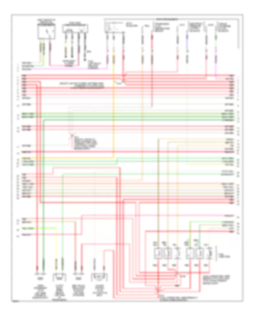
4.6L, Engine Performance Wiring Diagrams, Early Production (1 of 4) for Ford Pickup F150 1997
 https://portal-diagnostov.com/license.html
Automotive Electricians Portal FZCO
Automotive Electricians Portal FZCO
https://portal-diagnostov.com/license.html
https://portal-diagnostov.com/license.html
Automotive Electricians Portal FZCO
Automotive Electricians Portal FZCOList of elements for 4.6L, Engine Performance Wiring Diagrams, Early Production (1 of 4) for Ford Pickup F150 1997:
- (engine control harn, near breakout to pcm)
- (engine control sensor harn, near breakout to g123)
- (engine control sensor harn, near breakout to g123) s134
- (engine control sensor harn, near breakout to vapor management valve)
- (fuel charge harn, near breakout of 42-pin conn in right rear of engine compt) s117
- (fuel charge harn, near breakout to radio noise cap 1) s118
- (fuel charge harn, near breakout to radio noise cap 2) s119
- (left radiator support) g108
- (lower left cowl panel) g201
- (not used)
- (partial 16-pin connector)
- (partial: 42-pin connector)
- (rear of engine compt, right side of cowl panel)
- 4x4 hi/low indicator switch & generic electronic module
- 4x4 low ind sw
- 820 ohms
- Accs
- Air conditioning system
- C120
- C243
- Case gnd
- Ckp(+)
- Ckp(-)
- Data link (+)
- Data link (-)
- Data link connector (below center of i/p)
- Ect
- Ect gauge
- Engine fuse module (left side of engine compt)
- Evr ctrl
- Feps (eprom)
- Fuel pump mon
- Fuse 30a
- Fuse 5a
- G123
- Hot at all times
- Hot in run or start
- Iat
- Ign coil 1
- Ign coil 2
- Ignition coils 1 & 2
- Ignition coils 3 & 4
- Intake manifold tuning valve (top front of engine)
- Junction box fuse/relay panel (under left side of i/p)
- Maf
- Mil
- Nca
- Not used
- O/d off
- Octane adjust
- Pcm power diode
- Pcm power relay
- Power distribution box (left side of engine compt)
- Powertrain control module (right side of engine compt)
- Pwr gnd
- Radio noise capacitor 1
- Radio noise capacitor 2
- Red
- Red/ s225
- Rr ho2s sig (12)
- S100
- S106
- S107
- S116 (engine control sensor harn, near breakout to engine fuse module)
- S127
- S128
- S130
- Shift sol 1 (a/t)
- Shift sol 2 (a/t)
- Spark plugs
- Tach out
- Tcs (a/t)
- Tft
- Transmission control indicator lamp
- Transmission control switch (a/t)
- Tuning valve
- Vss (-)
4.6L, Engine Performance Wiring Diagrams, Early Production (2 of 4) for Ford Pickup F150 1997
 https://portal-diagnostov.com/license.html
Automotive Electricians Portal FZCO
Automotive Electricians Portal FZCO
https://portal-diagnostov.com/license.html
https://portal-diagnostov.com/license.html
Automotive Electricians Portal FZCO
Automotive Electricians Portal FZCOList of elements for 4.6L, Engine Performance Wiring Diagrams, Early Production (2 of 4) for Ford Pickup F150 1997:
- (engine control sensor harn, near breakout to 35-pin conn in left rear of engine compt) s139
- (engine control sensor harn, near breakout to 38-pin conn in right rear of engine compt)
- (lower left inner cowl panel)
- (speedometer/ odometer) vehicle speed input
- (under left side of i/p) junction box fuse/relay panel
- C236
- C237
- C243
- C267
- Crankshaft position sensor (lower front of engine)
- Crankshaft position sensor shield
- Differential pressure feedback egr sensor (right side of engine)
- Electronic suspension system
- Engine coolant temperature gauge
- Engine coolant temperature sender (left front corner of engine)
- Engine coolant temperature sensor (front of engine)
- Fuel pump relay
- Fuel reset switch indicator
- Fuel tank pressure sensor (at fuel tank)
- Fuse 20a
- G123 (rear of engine compt, right side of cowl panel)
- G200
- Generic electronic module/ central timer module
- Hot at all times
- Instrument cluster
- Intake air temperature sensor (on intake manifold)
- Malfunction indicator
- Nca
- Octane adjust shorting bar (right rear corner of engine compt)
- Power distribution box (left side of engine compt)
- Red
- Red/pnk
- S101 (engine control harn, in breakout to pcm)
- S123 (engine control harn, near breakout to starter motor relay)
- S135 (fuel charge harn, near breakout to radio noise capacitor)
- S136 (fuel charge harn, near breakout to fuel injector 3)
- S137 (fuel charge harn, near breakout to starter motor relay)
- S138
- S207
- Tachometer
- Throttle position sensor (attached to throttle body)
- Vss input
4.6L, Engine Performance Wiring Diagrams, Early Production (3 of 4) for Ford Pickup F150 1997
 https://portal-diagnostov.com/license.html
Automotive Electricians Portal FZCO
Automotive Electricians Portal FZCO
https://portal-diagnostov.com/license.html
https://portal-diagnostov.com/license.html
Automotive Electricians Portal FZCO
Automotive Electricians Portal FZCOList of elements for 4.6L, Engine Performance Wiring Diagrams, Early Production (3 of 4) for Ford Pickup F150 1997:
- (backup lamp sw to rear lamp feed harn, at breakout to 38-pin conn in right rear of engine compt)
- (fuel charge harn, near breakout to 42-pin conn in right rear of engine compt)
- (fuel tank) fuel pump module
- (left rear corner of engine compt)
- (right side of i/p) inertia fuel shut-off switch
- 4r70w transmission
- Egr vacuum regulator solenoid (left side of engine)
- Electronic pressure control solenoid
- Fuel injectors
- G108 (left front radiator support)
- Idle air control valve (on throttle body)
- Instrument cluster system
- Nca
- Output shaft speed sensor (left side of transmission)
- Red
- Red/pnk
- S129
- S131 (fuel charge harn, near breakout to radio noise capacitor)
- S140
- S141 (backup lamp sw to rear lamp feed harn, in breakout to 38-pin conn in right rear engine compt)
- S400
- Shift solenoids
- Tan
- Tan/ red
- Tan/red
- Torque converter clutch solenoid
- Transmission fluid temperature sensor
- Vapor management valve
4.6L, Engine Performance Wiring Diagrams, Early Production (4 of 4) for Ford Pickup F150 1997
 https://portal-diagnostov.com/license.html
Automotive Electricians Portal FZCO
Automotive Electricians Portal FZCO
https://portal-diagnostov.com/license.html
https://portal-diagnostov.com/license.html
Automotive Electricians Portal FZCO
Automotive Electricians Portal FZCOList of elements for 4.6L, Engine Performance Wiring Diagrams, Early Production (4 of 4) for Ford Pickup F150 1997:
- (engine control sensor harn, near breakout to vapor management valve)
- (front of left head) cylinder head temperature sensor
- (left rear of engine compt) speed control servo/amplifier assembly
- (left rear of transmission) vehicle speed sensor
- (main harn, near breakout to instrument cluster)
- (near fuel tank) canister vent solenoid
- (right side of engine) knock sensor
- 5v ref volt
- A/t
- Brake on/off
- Brake on/off switch
- C242
- Cam pos in
- Camshaft position sensor (left front of engine)
- Camshaft position sensor shield
- Canister vent
- Ccp sw/tr sens
- Cyl head temp
- Dpfe sens
- Epc sol
- Fuel inj 1
- Fuel inj 2
- Fuel inj 3
- Fuel inj 4
- Fuel inj 5
- Fuel inj 6
- Fuel inj 7
- Fuel inj 8
- Fuel pump ctrl
- Fuel tank press
- Fuse 15a
- G123 (rear of engine compt, on right side of cowl panel)
- G123 (rear of engine compt, right side of cowl panel)
- G200 (lower left cowl panel)
- Heater ctrl
- Hot at all times
- Iac sol
- Ign coil 3
- Ign coil 4
- Junction box fuse/relay panel (under left side of i/p)
- Kap b(+)
- Knock sensor
- Left front heated oxygen sensor (ho2s 21) (lower left rear of engine)
- Left rear heated oxygen sensor (ho2s 22) (left rear of transmission)
- Lf ho2s
- Lf ho2s sig (21)
- Lr ho2s
- Lr ho2s sig (22)
- M/t
- Maf sens in
- Mass air flow sensor (right side of engine compt, in air cleaner assembly)
- Nca
- Oss (+) (a/t)
- Powertrain control module (right side of engine compt)
- Pwr gnd
- Red
- Red/pnk
- Rf ho2s
- Rf ho2s sig (11)
- Right front heated oxygen sensor (ho2s 11) (lower right rear of engine)
- Right rear heated oxygen sensor (ho2s 12) (right rear of transmission)
- Rr ho2s
- S100
- S101
- S107
- S143
- S221
- S231
- Sig rtn
- Starting/ charging system
- Tan
- Tan/red
- Tcc sol
- Tp sens in
- Trans ctrl ind
- Transmission range sensor (a/t) (lower left side of transmission)
- Vapor valve
- Vpwr
- Vss (+)
- Vss input
4.6L, Engine Performance Wiring Diagrams, Late Production (1 of 4) for Ford Pickup F150 1997
 https://portal-diagnostov.com/license.html
Automotive Electricians Portal FZCO
Automotive Electricians Portal FZCO
https://portal-diagnostov.com/license.html
https://portal-diagnostov.com/license.html
Automotive Electricians Portal FZCO
Automotive Electricians Portal FZCOList of elements for 4.6L, Engine Performance Wiring Diagrams, Late Production (1 of 4) for Ford Pickup F150 1997:
- (engine control harn, near breakout to pcm)
- (engine control sensor harn, near breakout to g123)
- (engine control sensor harn, near breakout to vapor management valve)
- (fuel charge harn, near breakout of 42-pin conn in right rear of engine compt) s117
- (fuel charge harn, near breakout to radio noise cap 1) s118
- (fuel charge harn, near breakout to radio noise cap 2) s119
- (left radiator support) g108
- (lower left cowl panel) g201
- (not used)
- (partial: 16-pin connector)
- (partial: 42-pin connector)
- (rear of engine compt, right side of cowl panel) g123
- 4x4 hi/low indicator switch & generic electronic module
- 4x4 low ind sw
- 820 ohms
- Accs
- Air conditioning system
- C120
- C243
- Case gnd
- Ckp(+)
- Ckp(-)
- Data link (+)
- Data link (-)
- Data link connector (below center of i/p)
- Digital transmission range sensor (dtr sensor) (left side of transmission)
- Ect
- Ect gauge
- Engine fuse module (left side of engine compt)
- Evr ctrl
- Feps (eprom)
- Fp sending unit
- Fuel pump mon
- Fuse 30a
- Fuse 5a
- Hot at all times
- Hot in run or start
- Iat
- Ign coil 1
- Ign coil 2
- Ignition coils 1 & 2
- Ignition coils 3 & 4
- Instrument cluster system
- Intake manifold tuning valve (top front of engine)
- Junction box fuse/relay panel (under left side of i/p)
- Maf
- Mil
- Nca
- Not used
- O/d off
- Octane adjust
- Pcm power diode
- Pcm power relay
- Power distribution box (left side of engine compt)
- Powertrain control module (right side of engine compt)
- Pwr gnd
- R n
- Radio noise capacitor 1
- Radio noise capacitor 2
- Red
- Red/ s225
- Rr ho2s sig (12)
- S100
- S106
- S107
- S116 (engine control sensor harn, near breakout to engine fuse module)
- S127
- S128
- S130
- Shift sol 1 (a/t)
- Shift sol 2 (a/t)
- Spark plugs
- Tach out
- Tcs (a/t)
- Tft
- To dtr sensor (diagram 4 of 4)
- Tr1
- Tr2a
- Tr4a
- Transmission control indicator lamp
- Transmission control switch (a/t)
- Tuning valve
- Vss (-)
4.6L, Engine Performance Wiring Diagrams, Late Production (2 of 4) for Ford Pickup F150 1997
 https://portal-diagnostov.com/license.html
Automotive Electricians Portal FZCO
Automotive Electricians Portal FZCO
https://portal-diagnostov.com/license.html
https://portal-diagnostov.com/license.html
Automotive Electricians Portal FZCO
Automotive Electricians Portal FZCOList of elements for 4.6L, Engine Performance Wiring Diagrams, Late Production (2 of 4) for Ford Pickup F150 1997:
- (engine control sensor harn, near breakout to 35-pin conn in left rear of engine compt) s139
- (engine control sensor harn, near breakout to 38-pin conn in right rear of engine compt)
- (lower left inner cowl panel)
- (speedometer/ odometer) vehicle speed input
- (under left side of i/p) junction box fuse/relay panel
- C236
- C237
- C243
- C267
- Crankshaft position sensor (lower front of engine)
- Crankshaft position sensor shield
- Differential pressure feedback egr sensor (right side of engine)
- Electronic suspension system
- Engine coolant temperature gauge
- Engine coolant temperature sender (left front corner of engine)
- Engine coolant temperature sensor (front of engine)
- Fuel pump relay
- Fuel reset switch indicator
- Fuel tank pressure sensor (at fuel tank)
- Fuse 20a
- G123 (rear of engine compt, right side of cowl panel)
- G200
- Generic electronic module/ central timer module
- Hot at all times
- Instrument cluster
- Intake air temperature sensor (on intake manifold)
- Malfunction indicator
- Nca
- Octane adjust shorting bar (right rear corner of engine compt)
- Power distribution box (left side of engine compt)
- Red
- Red/pnk
- S101 (engine control harn, in breakout to pcm)
- S123 (engine control harn, near breakout to starter motor relay)
- S135 (fuel charge harn, near breakout to radio noise capacitor)
- S136 (fuel charge harn, near breakout to fuel injector 3)
- S137 (fuel charge harn, near breakout to starter motor relay)
- S138
- S207
- Tachometer
- Throttle position sensor (attached to throttle body)
- Vss input
4.6L, Engine Performance Wiring Diagrams, Late Production (3 of 4) for Ford Pickup F150 1997
 https://portal-diagnostov.com/license.html
Automotive Electricians Portal FZCO
Automotive Electricians Portal FZCO
https://portal-diagnostov.com/license.html
https://portal-diagnostov.com/license.html
Automotive Electricians Portal FZCO
Automotive Electricians Portal FZCOList of elements for 4.6L, Engine Performance Wiring Diagrams, Late Production (3 of 4) for Ford Pickup F150 1997:
- (backup lamp sw to rear lamp feed harn, at breakout to 38-pin conn in right rear of engine compt)
- (fuel charge harn, near breakout to 42-pin conn in right rear of engine compt)
- (fuel tank) fuel pump module
- (left rear corner of engine compt)
- (right side of i/p) inertia fuel shut-off switch
- 4r70w transmission
- Egr vacuum regulator solenoid (left side of engine)
- Electronic pressure control solenoid
- Fuel injectors
- G108 (left front radiator support)
- Idle air control valve (on throttle body)
- Instrument cluster system
- Nca
- Output shaft speed sensor (left side of transmission)
- Red
- Red/pnk
- S129
- S131 (fuel charge harn, near breakout to radio noise capacitor)
- S140
- S141 (backup lamp sw to rear lamp feed harn, in breakout to 38-pin conn in right rear engine compt)
- S400
- Shift solenoids
- Tan
- Tan/ red
- Tan/red
- Torque converter clutch solenoid
- Transmission fluid temperature sensor
- Vapor management valve
4.6L, Engine Performance Wiring Diagrams, Late Production (4 of 4) for Ford Pickup F150 1997
 https://portal-diagnostov.com/license.html
Automotive Electricians Portal FZCO
Automotive Electricians Portal FZCO
https://portal-diagnostov.com/license.html
https://portal-diagnostov.com/license.html
Automotive Electricians Portal FZCO
Automotive Electricians Portal FZCOList of elements for 4.6L, Engine Performance Wiring Diagrams, Late Production (4 of 4) for Ford Pickup F150 1997:
- (engine control sensor harn, near breakout to vapor management valve)
- (front of left head) cylinder head temperature sensor
- (left rear of engine compt) speed control servo/amplifier assembly
- (left rear of transmission) vehicle speed sensor
- (main harn, near breakout to instrument cluster)
- (near fuel tank) canister vent solenoid
- (right side of engine) knock sensor
- 240 ohms
- 5v ref volt
- A/t
- Brake on/off
- Brake on/off switch
- C242
- Cam pos in
- Camshaft position sensor (left front of engine)
- Camshaft position sensor shield
- Canister vent
- Ccp/dtr
- Cyl head temp
- Digital transmission range sensor (dtr sensor-a/t) (left side of transmission)
- Dpfe sens
- Epc sol
- From dtr sensor (diagram 1 of 4)
- Fuel inj 1
- Fuel inj 2
- Fuel inj 3
- Fuel inj 4
- Fuel inj 5
- Fuel inj 6
- Fuel inj 7
- Fuel inj 8
- Fuel pump ctrl
- Fuse 15a
- G123 (rear of engine compt, on right side of cowl panel)
- G123 (rear of engine compt, right side of cowl panel)
- G200 (lower left cowl panel)
- Heater ctrl
- Hot at all times
- Iac sol
- Ign coil 3
- Ign coil 4
- Junction box fuse/relay panel (under left side of i/p)
- Kap b(+)
- Knock sensor
- Left front heated oxygen sensor (ho2s 21) (lower left rear of engine)
- Left rear heated oxygen sensor (ho2s 22) (left rear of transmission)
- Lf ho2s
- Lf ho2s sig (21)
- Lr ho2s
- Lr ho2s sig (22)
- M/t
- Maf sens in
- Mass air flow sensor (right side of engine compt, in air cleaner assembly)
- Nca
- Oss (+) (a/t)
- Powertrain control module (right side of engine compt)
- Pwr gnd
- Red
- Red/pnk
- Rf ho2s
- Rf ho2s sig (11)
- Right front heated oxygen sensor (ho2s 11) (lower right rear of engine)
- Right rear heated oxygen sensor (ho2s 12) (right rear of transmission)
- Rr ho2s
- S100
- S101
- S107
- S143
- S221
- S231
- Sig rtn
- Starting/charging system
- Tan
- Tan/red
- Tcc sol
- Tp sens in
- Trans ctrl ind
- Vapor valve
- Vpwr
- Vss (+)
- Vss input
5.4L
5.4L, Engine Performance Wiring Diagrams (1 of 4) for Ford Pickup F150 1997
 https://portal-diagnostov.com/license.html
Automotive Electricians Portal FZCO
Automotive Electricians Portal FZCO
https://portal-diagnostov.com/license.html
https://portal-diagnostov.com/license.html
Automotive Electricians Portal FZCO
Automotive Electricians Portal FZCOList of elements for 5.4L, Engine Performance Wiring Diagrams (1 of 4) for Ford Pickup F150 1997:
- (engine control harn, near breakout to pcm)
- (engine control sensor harn, near breakout to vapor management valve)
- (expedition)
- (fuel charge harn, in breakout to fuel injector 3)
- (fuel charge harn, in breakout to fuel injector 7)
- (fuel charge harn, near breakout to 42-pin inline conn in right rear of engine compt)
- (left radiator support) g108
- (lower left cowl panel) g201
- (overhead console)
- (rear of engine compt)
- 4x4 low ind sw
- A/c on sig
- Air conditioning system
- Air suspn vss
- Body computer system
- C243
- Case gnd
- Ckp (+)
- Ckp (-)
- Data link (+)
- Data link (-)
- Data link connector (partial) (center of dash)
- Digital transmission range sensor (dtr sensor) (left side of transmission)
- Dtr-tr1
- Dtr-tr2
- Dtr-tr4
- E4od ccs
- E4od ss1
- E4od ss2
- Ect
- Electronic suspension system
- Engine fuse module (left side of engine compt)
- Evr sol
- Feps (eprom)
- Fp sending unit
- Fuel pump mon
- Fuse 30a
- Fuse 5a
- G123
- Hot at all times
- Hot in run or start
- Iat
- Ign coil 1
- Ign coil 3
- Ign coil 5
- Ign coil 6
- Ignition coils
- Instrument cluster system
- Intake tune vlv
- Junction box fuse/relay panel (under left side of dash)
- Maf
- Mil
- Nca
- O/d off
- Octane adjust
- Od off ind
- Ohms
- Otc module
- Pcm power diode
- Pcm power relay
- Power distribution box (left side of engine compt)
- Powertrain control module (right side of engine compt)
- Pwr gnd
- R n
- Radio noise capacitor
- Red
- Rr ho2s (12)
- S100
- S106
- S107
- S116
- S117
- S127
- S128
- S161
- S162
- S225
- Tach
- Tcs
- Tft
- To dtr sensor (diagram 4 of 4)
- Transmission control indicator lamp
- Transmission control switch
- Vss (-)
5.4L, Engine Performance Wiring Diagrams (2 of 4) for Ford Pickup F150 1997
 https://portal-diagnostov.com/license.html
Automotive Electricians Portal FZCO
Automotive Electricians Portal FZCO
https://portal-diagnostov.com/license.html
https://portal-diagnostov.com/license.html
Automotive Electricians Portal FZCO
Automotive Electricians Portal FZCOList of elements for 5.4L, Engine Performance Wiring Diagrams (2 of 4) for Ford Pickup F150 1997:
- (engine control sensor harn, near breakout to 35-pin conn in left rear of engine compt) s139
- (engine control sensor harn, near breakout to 38-pin conn in right rear of engine compt)
- (lower left kick panel)
- (speedometer/ odometer) vehicle speed input
- (under left side of dash) junction box fuse/relay panel
- C236
- C237
- C243
- C267
- Crankshaft position sensor (lower front of engine)
- Crankshaft position sensor shield
- Differential pressure feedback egr sensor (left side of engine)
- Electronic suspension system
- Engine coolant temperature gauge
- Engine coolant temperature sender (left front corner of engine)
- Fuel pump relay
- Fuel reset switch indicator
- Fuel tank pressure sensor (at fuel tank)
- Fuse 20a
- G123 (rear of engine compt)
- G200
- Generic electronic module/ central timer module
- Hot at all times
- Instrument cluster
- Intake air temperature sensor (on intake manifold)
- Knock sensor (top right rear side of engine)
- Knock sensor shield
- Malfunction indicator
- Nca
- Octane adjust shorting bar (right rear corner of engine compt)
- Power distribution box (left side of engine compt)
- Red
- Red/pnk
- S101 nca
- S123 (engine control harn, near breakout to starter motor relay)
- S135 (fuel charge harn, near breakout to radio noise capacitor)
- S136 (fuel charge harn, near breakout to fuel injector 3)
- S137 (fuel charge harn, near breakout to starter motor relay)
- S138
- S199 nca
- S207
- Tachometer
- Throttle position sensor (attached to throttle body)
- Vss input
5.4L, Engine Performance Wiring Diagrams (3 of 4) for Ford Pickup F150 1997
 https://portal-diagnostov.com/license.html
Automotive Electricians Portal FZCO
Automotive Electricians Portal FZCO
https://portal-diagnostov.com/license.html
https://portal-diagnostov.com/license.html
Automotive Electricians Portal FZCO
Automotive Electricians Portal FZCOList of elements for 5.4L, Engine Performance Wiring Diagrams (3 of 4) for Ford Pickup F150 1997:
- (backup lamp sw to rear lamp feed harn, at breakout to 38-pin conn in right rear of engine compt)
- (backup lamp sw to rear lamp feed harn, in breakout to 38-pin conn in right rear engine compt)
- (fuel charge harn, near breakout to 42-pin conn in right rear of engine compt)
- (fuel tank) fuel pump module
- (right side of dash) inertia fuel shut-off switch
- Coast clutch solenoid
- E4od transmission
- Egr vacuum regulator solenoid (left side of engine)
- Electronic pressure control solenoid
- Fuel injectors
- G108 (left front radiator support)
- Idle air control valve (on left side of intake manifold)
- Instrument cluster system
- Intake manifold tuning valve (on left side of engine)
- Nca
- Red
- Red/pnk
- S129
- S131 (fuel charge harn, near breakout to radio noise capacitor)
- S140
- S141
- S400
- Shift solenoid
- Tan
- Tan/ red
- Tan/red
- Torque converter clutch solenoid
- Transmission fluid temperature sensor
- Vapor management valve (vmv) (left rear corner of engine compt)
5.4L, Engine Performance Wiring Diagrams (4 of 4) for Ford Pickup F150 1997
 https://portal-diagnostov.com/license.html
Automotive Electricians Portal FZCO
Automotive Electricians Portal FZCO
https://portal-diagnostov.com/license.html
https://portal-diagnostov.com/license.html
Automotive Electricians Portal FZCO
Automotive Electricians Portal FZCOList of elements for 5.4L, Engine Performance Wiring Diagrams (4 of 4) for Ford Pickup F150 1997:
- (engine control sensor harn, near breakout to c165, windshield wiper motor)
- (front of left head) cylinder head temperature sensor
- (left rear of engine compt) speed control servo/amplifier assembly
- (left rear of transmission) vehicle speed sensor
- (main harn, near breakout to 16-pin inline conn behind left side of dash)
- (near fuel tank) canister vent solenoid
- 270 ohms
- 5v ref
- Brake on/off
- Brake on/off switch
- C242
- Camshaft position sensor (left front of engine)
- Camshaft position sensor shield
- Canister vent
- Cmp sensor
- Cyl head temp
- Digital transmission range sensor (dtr sensor-a/t) (left side of transmission)
- Dpfe sens
- Dtr-tr3a
- Epc sol
- From dtr sensor (diagram 1 of 4)
- Fuel inj 1
- Fuel inj 2
- Fuel inj 3
- Fuel inj 4
- Fuel inj 5
- Fuel inj 6
- Fuel inj 7
- Fuel inj 8
- Fuel pump ctrl
- Fuel tank press
- Fuse 15a
- G123 (rear of engine compt)
- G200 (lower left kick panel)
- Heater ctrl
- Hot at all times
- Idle air ctrl
- Ign coil 2
- Ign coil 4
- Ign coil 7
- Ign coil 8
- Junction box fuse/relay panel (under left side of dash)
- Kap b(+)
- Knock sensor
- Left front heated oxygen sensor (ho2s 21) (lower left rear of engine)
- Left rear heated oxygen sensor (ho2s 22) (left rear of transmission)
- Lf ho2s
- Lf ho2s sig (21)
- Lr ho2s
- Maf sens in
- Mass air flow sensor (right side of engine compt, in air cleaner assembly)
- Nca
- Powertrain control module (right side of engine compt)
- Pwr gnd
- Red
- Red/pnk
- Rf ho2s
- Rf ho2s sig (11)
- Rf ho2s sig (22)
- Right front heated oxygen sensor (ho2s 11) (lower right rear of engine)
- Right rear heated oxygen sensor (ho2s 12) (right rear of transmission)
- Rr ho2s
- S100
- S101
- S107
- S143
- S199
- S231
- Sig rtn
- Tan
- Tan/red
- Tcc sol
- Tp sens in
- Vapor valve
- Vpwr
- Vss (+)
- Vss input
EXTERIOR LIGHTS
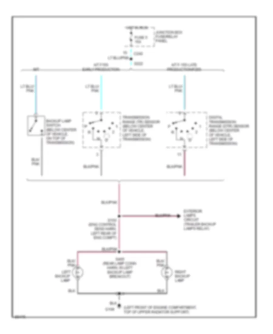
Back-up Lamps Wiring Diagram for Ford Pickup F150 1997
 https://portal-diagnostov.com/license.html
Automotive Electricians Portal FZCO
Automotive Electricians Portal FZCO
https://portal-diagnostov.com/license.html
https://portal-diagnostov.com/license.html
Automotive Electricians Portal FZCO
Automotive Electricians Portal FZCOList of elements for Back-up Lamps Wiring Diagram for Ford Pickup F150 1997:
- (left front of engine compartment, top of upper radiator support)
- A/t f-150 late production/f250
- A/t f150 early production
- Backup
- Backup lamp switch (below center of vehicle, on top of transmission)
- C242
- Digital transmission range (dtr) sensor (below center of vehicle, left side of transmission)
- Exterior lamps circuit (trailer backup lamps relay)
- Fuse 5 15a
- G108
- Hot in run
- Junction box fuse/relay panel
- Lamp
- Left
- M/t
- P p p
- Right backup lamp
- S150 (eng control sens harn, left rear of eng compt)
- S222
- S401
- S405 (rear lamp conn harn, in left backup lamp breakout)
- Transmission range (tr) sensor (below center of vehicle, left side of transmission)
Exterior Lamps Wiring Diagram for Ford Pickup F150 1997
 https://portal-diagnostov.com/license.html
Automotive Electricians Portal FZCO
Automotive Electricians Portal FZCO
https://portal-diagnostov.com/license.html
https://portal-diagnostov.com/license.html
Automotive Electricians Portal FZCO
Automotive Electricians Portal FZCOList of elements for Exterior Lamps Wiring Diagram for Ford Pickup F150 1997:
- (eng cntrl sensor harn, in eng fuse module breakout) s149
- (eng cntrl sensor harn, near high mount stop lamp breakout)
- (left front radiator support)
- (main harn, near main light switch breakout) s224
- (rear lamp conn harn, left rear of vehicle)
- (socket assembly harn, near license lamp breakout)
- Blower/ flasher relay block
- Brake on/ off (boo) switch (behind left side i/p, top left side of brake/clutch pedal support)
- C237
- C242
- C243
- Cargo/ high mount stop lamp
- Center cargo/ high mount stop lamp
- F-150 early production
- F-150 late production/ f-250
- Flasher relay
- Fuse 10a
- Fuse 15a
- G108
- G109 (right front radiator support)
- G203 (lower right cowl panel)
- Hazard
- Head
- High mount stop lamp
- Hot at all times
- Hot in run
- Instrument cluster
- Junction box fuse/relay panel
- Left
- Left front park/turn lamp
- Left rear park/stop/ turn lamp
- Left tail/ side marker lamp
- Left turn indicator
- License lamps
- Main light switch
- Multi-function switch
- Nca
- Normal
- Off
- Park
- Power distribution box
- Right
- Right front park/turn lamp
- Right rear park/stop/ turn lamp
- Right tail/ side marker lamp
- Right turn indicator
- S104
- S115 (eng cntrl sensor harn, left side of eng compt)
- S148
- S202
- S206
- S211
- S221 (rabs only)
- S228
- S246 (main harn, behind left side of i/p)
- S247 (main harn, behind left side of i/p)
- S401
- S402
- S403
- S404
- Trailer/ camper adapter
- W/ flare side only
- W/ rear bumper
Trailer/Camper Adapter Wiring Diagram for Ford Pickup F150 1997
 https://portal-diagnostov.com/license.html
Automotive Electricians Portal FZCO
Automotive Electricians Portal FZCO
https://portal-diagnostov.com/license.html
https://portal-diagnostov.com/license.html
Automotive Electricians Portal FZCO
Automotive Electricians Portal FZCOList of elements for Trailer/Camper Adapter Wiring Diagram for Ford Pickup F150 1997:
- (eng cntrl sensor harn, in engine fuse module breakout) s149
- (eng cntrl sensor harn, near high mount stop lamp breakout) s148
- (engine cntrl sensor harn, left side of eng compt)
- (left front radiator support) g108
- (lower right cowl panel)
- Back-up lamps circuit
- Brake on/off & right turn signal output
- Brake on/off (boo) switch
- Brake on/off or left turn signal output
- C242
- Engine fuse module
- Exterior lights system
- Fuse 1 20a
- Fuse 10a
- Fuse 15a
- Fuse 16 40a
- Fuse 20a
- Fuse 28 30a
- G203
- G416 (left rear of frame)
- Head
- Hot at all times
- Hot in run
- Instrument cluster breakout)
- Junction box fuse/relay panel
- Main light switch
- Multi- function switch
- Nca
- Off
- Park
- Power distribution box
- Power distribution center
- Rear exterior lamps
- Red
- S105
- S108
- S110
- S111
- S115
- S200
- S221
- S224 (main harn, in main light switch breakout)
- S228
- Trailer electronic brake control
- Trailer electronic brake control unit
- Trailer tow backup lamp relay
- Trailer tow battery charge relay
- Trailer tow left turn relay
- Trailer tow right turn relay
- Trailer tow running lamp relay
- Trailer/ camper adapter
- Trailer/ camper adapter (trailer backup lamps)
- Trailer/ camper adapter (trailer battery)
- Trailer/ camper adapter (trailer ground)
- Trailer/ camper adapter (trailer left turn lamps)
- Trailer/ camper adapter (trailer right turn lamps)
- Trailer/ camper adapter (trailer running lamps)
GROUND DISTRIBUTION
Ground Distribution Wiring Diagram (1 of 3) for Ford Pickup F150 1997
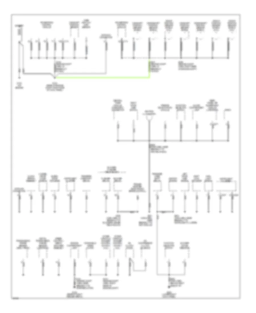 https://portal-diagnostov.com/license.html
Automotive Electricians Portal FZCO
Automotive Electricians Portal FZCO
https://portal-diagnostov.com/license.html
https://portal-diagnostov.com/license.html
Automotive Electricians Portal FZCO
Automotive Electricians Portal FZCOList of elements for Ground Distribution Wiring Diagram (1 of 3) for Ford Pickup F150 1997:
- (main harn, near breakout to rpo relay box)
- 4 wheel drive mode switch
- 48 (bare)
- A/c clutch diode
- A/c compressor clutch solenoid
- Ashtray illumination
- Battery
- Blend door actuator
- Blower motor resistor
- Blower relay
- Blower/ flasher relay block
- C174 48 (bare)
- Camshaft position sensor
- Camshaft position sensor shield
- Central timer module diagnostic connector
- Clock spring assembly
- Crankshaft position sensor shield
- Datalink connector
- Digital transmission range sensor (late prod)
- Engine compartment lamp
- Flasher relay
- Function selector switch
- G105 (rear of right fender apron)
- G123 (rear of engine compt, right side of cowl panel)
- G133 (on engine)
- G203 (lower right cowl panel)
- Glove compartment lamp
- Ignition switch
- Instrument cluster
- Intake manifold runner control motor 1 (4.2l)
- Intake manifold runner control motor 2 (4.2l)
- Knock position sensor shield (5.4l)
- Left door ajar switch
- Main light switch
- Mass air flow (maf) sensor
- Passive de-activation module
- Powertrain control module
- Radio
- Rear wheel air suspension module (late prod)
- Right door ajar switch
- S100 (engine compt harn, in breakout to pcm)
- S101 (engine compt harn, in breakout to pcm)
- S102 (engine compt harn, near breakout to starter motor)
- S103 (engine compt harn, right rear of engine compt)
- S199 (engine compt harn, right rear of engine compt)
- S200 (main harn, behind right side of i/p)
- S201 (main harn, near breakout to evo module)
- S202 (main harn, in breakout to blower/flasher relay block)
- S204 (main harn, near breakout to instrument cluster)
- Shift lock actuator
- Speed control/ servo amplifier assembly
- Trailer adapter (electronic brake control)
- Transfer case shift relay
- Transmission range sensor (early prod)
- Windshield wiper motor
Ground Distribution Wiring Diagram (2 of 3) for Ford Pickup F150 1997
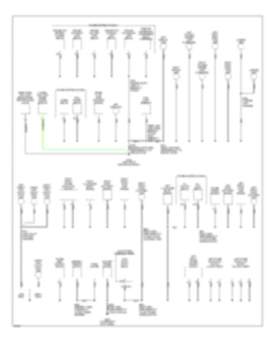 https://portal-diagnostov.com/license.html
Automotive Electricians Portal FZCO
Automotive Electricians Portal FZCO
https://portal-diagnostov.com/license.html
https://portal-diagnostov.com/license.html
Automotive Electricians Portal FZCO
Automotive Electricians Portal FZCOList of elements for Ground Distribution Wiring Diagram (2 of 3) for Ford Pickup F150 1997:
- (rear lamp harn, near breakout to fuel pump assembly) s400
- 4 wheel anti-lock brake system module
- 4wabs relay
- 87a
- All lock relay
- All unlock relay
- Auxiliary power socket
- Brake fluid level indicator switch
- Cargo/ high mount stop lamp
- Cigar lighter
- Early prod
- Fuel pump assembly
- G108 (left front radiator support)
- G203 (lower right cowl panel)
- Junction box fuse/relay panel
- Late prod
- Left backup lamp
- Left cargo/ high mount stop lamp
- Left door anti-theft switch
- Left front door ajar switch
- Left front door courtesy lamp
- Left front power window switch
- Left headlamp
- Left illuminated entry switch
- Left power door lock switch (w/ anti-theft)
- Left power door lock switch (w/o anti-theft)
- Left stop/ park/ turn lamp
- Left tail/side marker lamp (flare side)
- License lamp
- One touch down relay
- Pcm power relay
- Power distribution box
- Power mirror switch
- Power seat control switch
- Rear air suspension compressor relay (late prod)
- Rear wheel anti-lock brake system proportioning valve
- Right backup lamp
- Right cargo/ high mount stop lamp
- Right door anti-theft switch
- Right front door ajar switch
- Right front door courtesy lamp
- Right front power door lock switch
- Right illuminated entry switch
- Right stop/ park/ turn lamp
- Right tail/side marker lamp (flare side)
- S105 (engine compt harn, in breakout to pdc)
- S106 (engine compt harn, near breakout to ground g108)
- S205 (main harn, near breakout to evo module)
- S206 (seatbelt harn, in breakout to right rear speaker)
- S401 (rear lamp harn, near breakout to backup lamps)
- S402 (license lamp harness)
- S500 (body harn, near breakout to left power mirror switch)
- S501 (body harn, near breakout to left power mirror switch)
- S600 (body harn, near breakout to right door courtesy lamp)
- S911 (high mount stoplamp harness)
- Seatbelt warning switch
- Trailer tow backup lamp relay
- Trailer tow battery charge relay
- Trailer tow left turn relay
- Trailer tow right turn relay
- Trailer tow running lamp relay
Ground Distribution Wiring Diagram (3 of 3) for Ford Pickup F150 1997
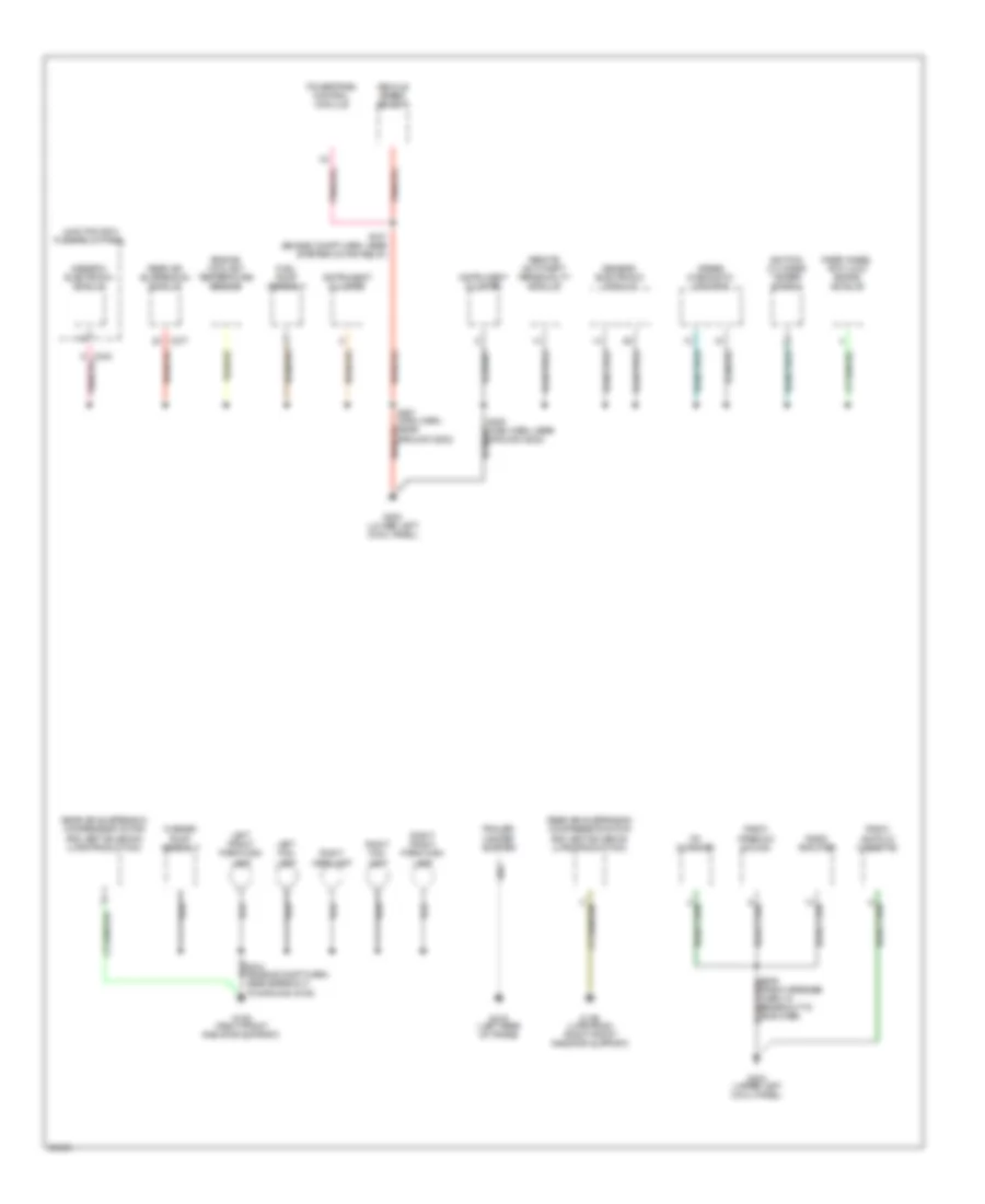 https://portal-diagnostov.com/license.html
Automotive Electricians Portal FZCO
Automotive Electricians Portal FZCO
https://portal-diagnostov.com/license.html
https://portal-diagnostov.com/license.html
Automotive Electricians Portal FZCO
Automotive Electricians Portal FZCOList of elements for Ground Distribution Wiring Diagram (3 of 3) for Ford Pickup F150 1997:
- Airbag diagnostic monitor
- C242
- C277
- Cd changer
- Engine coolant temperature sensor
- Fuel pump assembly
- G109 (late prod) (right front radiator support)
- G109 (right front radiator support)
- G200 (lower left cowl panel)
- G202 (upper left cowl panel)
- G416 (left rear of frame)
- Generic electronic module
- Ground g202)
- Ignition cylinder tamper switch
- Instrument cluster
- Junction box fuse/relay panel
- Left fog lamp
- Left front park/turn lamp
- Powertrain control module
- Radio (am/fm w/ cassette)
- Radio (premium sound)
- Radio amplifier
- Rear air suspension compressor motor and vent solenoid (late production)
- Rear air suspension module
- Rear wheel anti-lock brake module
- Remote anti-theft personality module
- Right fog lamp
- Right front park/turn lamp
- Right headlamp
- S104 (engine compt harn, near breakout to ground g109)
- S107 (engine compt harn, near starter motor relay)
- Trailer/ camper adapter
- Vehicle speed sensor
- Washer pump assembly
HEADLIGHTS
Autolamps Wiring Diagram, with DRL for Ford Pickup F150 1997
 https://portal-diagnostov.com/license.html
Automotive Electricians Portal FZCO
Automotive Electricians Portal FZCO
https://portal-diagnostov.com/license.html
https://portal-diagnostov.com/license.html
Automotive Electricians Portal FZCO
Automotive Electricians Portal FZCOList of elements for Autolamps Wiring Diagram, with DRL for Ford Pickup F150 1997:
- (eng control sensor harn, near breakout to left headlamp)
- (main harn, in main light switch breakout)
- (main harn, in pass air bag breakout)
- Auto- lamp on
- Auto- lamp on ind
- Autolamp module (behind center of i/p)
- Battery
- Brake ind out
- C236
- C237
- C242
- C243
- C244
- C245
- C246
- Daytime running lamps (drl) module (left front of engine compartment)
- Fog lamp relay
- Fog lamp sw
- Fog on ind
- Fuse 10a
- Fuse 15a
- Fuse 20a
- Fuse 30a
- Fuse 5a
- G108 (left front radiator support)
- G109 (right front radiator support)
- G203 (lower right cowl panel)
- Head
- Headlamp relay
- Headlamp)
- Headlamps
- Headlmps
- Hi-beam indicator
- Hot at all times
- Hot in run
- Hot in start or run
- Ignition
- Ind feed
- Instrument cluster
- Instrument cluster system (brake ind)
- Junction box fuse/relay panel
- Left fog lamp
- Left headlamp
- Main light
- Main light switch
- Multi- function switch
- Off
- Park
- Park brake input
- Park brake switch (right side of park brake lever)
- Park lamp relay
- Pass
- Power distribution box
- Relay output
- Right fog lamp
- Right headlamp
- Rpo relay box (behind right side of i/p)
- S104
- S106
- S109
- S112
- S114
- S147 (eng control sensor harn, in left fog lamp breakout)
- S204
- S211
- S212
- S219
- S224
- S225
- S245
- Switch
Autolamps Wiring Diagram, without DRL for Ford Pickup F150 1997
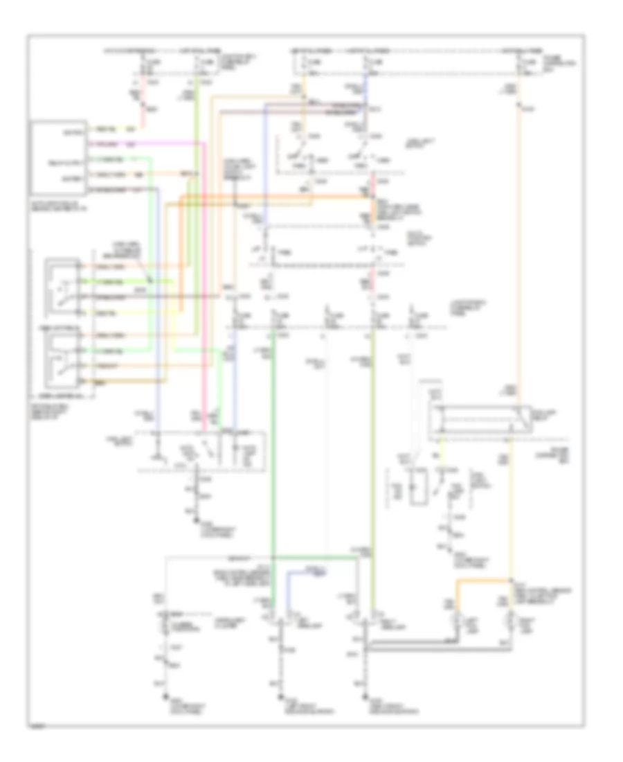 https://portal-diagnostov.com/license.html
Automotive Electricians Portal FZCO
Automotive Electricians Portal FZCO
https://portal-diagnostov.com/license.html
https://portal-diagnostov.com/license.html
Automotive Electricians Portal FZCO
Automotive Electricians Portal FZCOList of elements for Autolamps Wiring Diagram, without DRL for Ford Pickup F150 1997:
- (eng control sensor harn, near breakout to left headlamp)
- (main harn, in main light switch breakout)
- (main harn, in pass air bag breakout)
- Auto- lamp on
- Auto- lamp on ind
- Autolamp module (behind center of i/p)
- Battery
- C236
- C237
- C242
- C243
- C244
- C245
- C246
- Fog lamp relay
- Fog lamp sw
- Fog on ind
- Fuse 10a
- Fuse 15a
- Fuse 20a
- Fuse 30a
- Fuse 5a
- G108 (left front radiator support)
- G109 (right front radiator support)
- G203 (lower right cowl panel)
- Head
- Headlamp relay
- Hi-beam indicator
- Hot at all times
- Hot in start or run
- Ignition
- Instrument cluster
- Junction box fuse/relay panel
- Left fog lamp
- Left headlamp
- Main light
- Main light switch
- Multi- function switch
- Off
- Park
- Park lamp relay
- Pass
- Power distribution box
- Relay output
- Right fog lamp
- Right headlamp
- Rpo relay box (behind right side of i/p)
- S104
- S106
- S109
- S114
- S147 (eng control sensor harn, in left fog lamp breakout)
- S204
- S211
- S212
- S219
- S224
- S225
- S245
- Switch
Headlamps Wiring Diagram, with DRL for Ford Pickup F150 1997
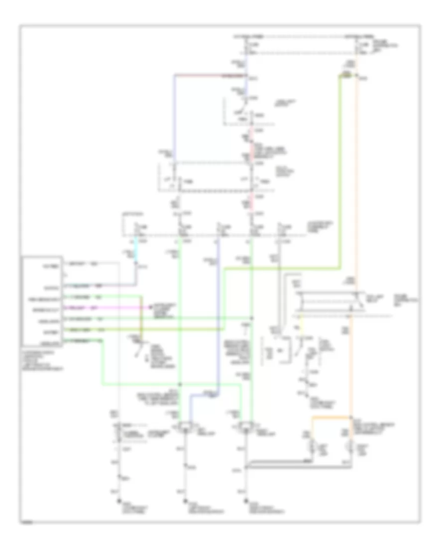 https://portal-diagnostov.com/license.html
Automotive Electricians Portal FZCO
Automotive Electricians Portal FZCO
https://portal-diagnostov.com/license.html
https://portal-diagnostov.com/license.html
Automotive Electricians Portal FZCO
Automotive Electricians Portal FZCOList of elements for Headlamps Wiring Diagram, with DRL for Ford Pickup F150 1997:
- (eng control sensor harn, 215 mm from breakout to right headlamp)
- (eng control sensor harn, near breakout to left headlamp)
- Battery
- Brake ind out
- C236
- C237
- C242
- C243
- C244
- C246
- Daytime running lamps (drl) module (left front of engine compartment)
- Fog lamp relay
- Fog lamp sw
- Fog on ind
- Fuse 10a
- Fuse 15a
- Fuse 20a
- Fuse 30a
- Fuse 5a
- G108 (left front radiator support)
- G109 (right front radiator support)
- G203 (lower right cowl panel)
- Head
- Headlamps
- Headlmps
- Hi-beam indicator
- Hot at all times
- Hot in run
- Ignition
- Ind feed
- Instrument cluster
- Instrument cluster system (brake ind)
- Junction box fuse/relay panel
- Left fog lamp
- Left headlamp
- Main light
- Main light switch
- Multi- function switch
- Off
- Park
- Park brake input
- Park brake switch (right side of park brake lever)
- Pass
- Power distribution box
- Right fog lamp
- Right headlamp
- S104
- S106
- S109
- S112
- S114
- S122
- S147 (eng control sensor harn, in left fog lamp breakout)
- S204
- S212
- Switch
Headlamps Wiring Diagram, without DRL for Ford Pickup F150 1997
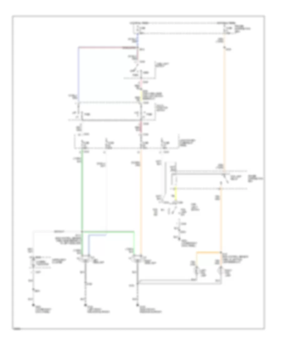 https://portal-diagnostov.com/license.html
Automotive Electricians Portal FZCO
Automotive Electricians Portal FZCO
https://portal-diagnostov.com/license.html
https://portal-diagnostov.com/license.html
Automotive Electricians Portal FZCO
Automotive Electricians Portal FZCOList of elements for Headlamps Wiring Diagram, without DRL for Ford Pickup F150 1997:
- (eng control sensor harn, near breakout to left headlamp)
- C236
- C237
- C242
- C243
- C244
- C246
- Fog lamp relay
- Fog lamp sw
- Fog on ind
- Fuse 10a
- Fuse 15a
- Fuse 20a
- Fuse 30a
- Fuse 5a
- G108 (left front radiator support)
- G109 (right front radiator support)
- G203 (lower right cowl panel)
- Head
- Hi-beam indicator
- Hot at all times
- Instrument cluster
- Junction box fuse/relay panel
- Left fog lamp
- Left headlamp
- Main light
- Main light switch
- Multi- function switch
- Off
- Park
- Pass
- Power distribution box
- Right fog lamp
- Right headlamp
- S104
- S106
- S109
- S114
- S147 (eng control sensor harn, in left fog lamp breakout)
- S204
- S212
- Switch
HORN
Horn Wiring Diagram for Ford Pickup F150 1997
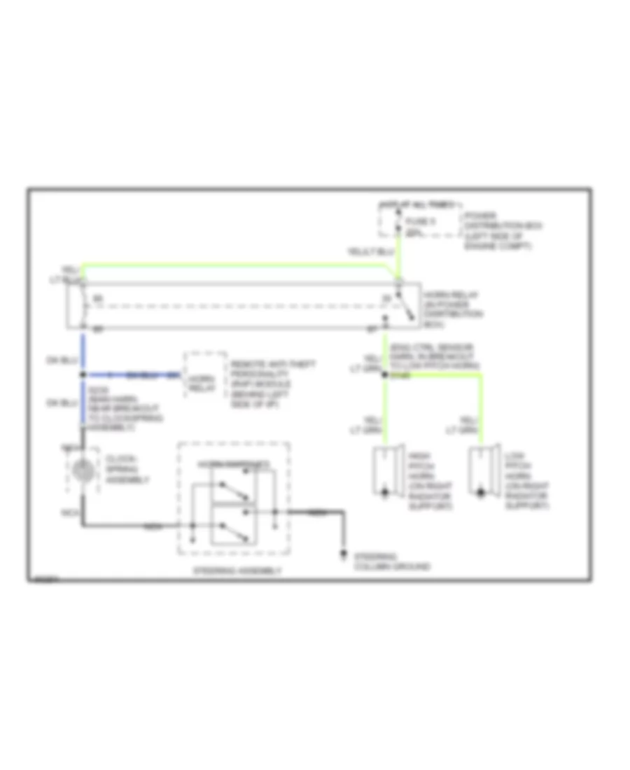 https://portal-diagnostov.com/license.html
Automotive Electricians Portal FZCO
Automotive Electricians Portal FZCO
https://portal-diagnostov.com/license.html
https://portal-diagnostov.com/license.html
Automotive Electricians Portal FZCO
Automotive Electricians Portal FZCOList of elements for Horn Wiring Diagram for Ford Pickup F150 1997:
- Clock- spring assembly
- Fuse 5 20a
- High pitch horn (on right radiator support)
- Horn relay
- Horn relay (in power disrtibution box)
- Horn switches
- Hot at all times
- Low pitch horn (on right radiator support)
- Nca
- Power distribution box (left side of engine compt)
- Remote anti-theft personality (rap) module (behind left side of i/p)
- S230 (main harn, near breakout to clockspring assembly)
- Steering assembly
- Steering column ground
- To low pitch horn) s145
INSTRUMENT CLUSTER
Instrument Cluster Wiring Diagram for Ford Pickup F150 1997
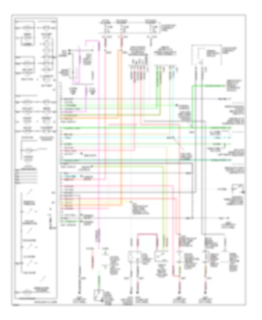 https://portal-diagnostov.com/license.html
Automotive Electricians Portal FZCO
Automotive Electricians Portal FZCO
https://portal-diagnostov.com/license.html
https://portal-diagnostov.com/license.html
Automotive Electricians Portal FZCO
Automotive Electricians Portal FZCOList of elements for Instrument Cluster Wiring Diagram for Ford Pickup F150 1997:
- (behind center of i/p) generic electronic module (gem)
- (behind right side of i/p) rear air suspension datalink
- (center of i/p) rear wheel air suspension module
- (conn a)
- (conn b)
- (conn c)
- (lower left cowl panel)
- (right side of engine compt) powertrain control module
- 4x4 high
- 4x4 low
- A11
- A12
- Air suspension
- Airbag
- Airbag diagnostic monitor (behind right side of i/p)
- All wheel anti-lock
- Anti- lock brakes
- Anti-lock
- Anti-lock brake module (left side of eng compt)
- Anti-theft
- B10
- B11
- B12
- B14
- B15
- B16
- Brake
- Brake warning diode
- C10
- C11
- C12
- C174
- C236
- C237
- C238
- C239
- C241
- C242
- C243
- Charge
- Coolant temperature
- Daytime running lamps module (left front of engine compt)
- Door ajar
- Ect
- Engine controls
- Engine coolant temperature sender (left front of engine compt)
- Engine oil pressure
- Engine oil pressure switch (near power steering pump)
- Exterior lights
- Fuel
- Fuel gauge
- Fuel pump assembly (in fuel tank)
- Fuel reset
- Fuse 10a
- Fuse 5a
- G200 (lower left cowl panel)
- G200 g108 (left front radiator support)
- G203 (lower right cowl panel)
- Generic electronic module
- Headlights
- Hot at all times
- Hot in run or start
- Illumination
- Inertia fuel shutoff (behind right side of i/p)
- Instrument cluster
- Interior lights
- Junction box fuse/relay panel
- Left turn
- Low fuel
- Low oil/ high coolant
- Main harn, near airbag diagnostic monitor)
- Main harn, near instr cluster)
- Malfunction indicator
- Mil
- Park brake switch (on park brake lever)
- Passive anti-theft control module (center of i/p)
- Rear wheel anti-lock
- Right turn
- S107
- S123 (engine compt harn, near starter mtr relay)
- S124 (left side of engine compt)
- S151 (engine compt harn, near breakout to washer motor)
- S201
- S204
- S207
- S208
- S225
- S232
- S289
- S294
- S400
- Seatbelt
- Solid state
- Speed control servo/ amplifier (left rear of engine compt)
- Speedo
- Speedometer/ odometer
- Starting/ charging
- Tach
- Tachometer
- Vehicle speed sensor (left rear of trans)
- Voltmeter
- W/ all wheel abs
- W/ drl
- W/ rear wheel abs
- W/o drl
INTERIOR LIGHTS
Courtesy Lamp Wiring Diagram for Ford Pickup F150 1997
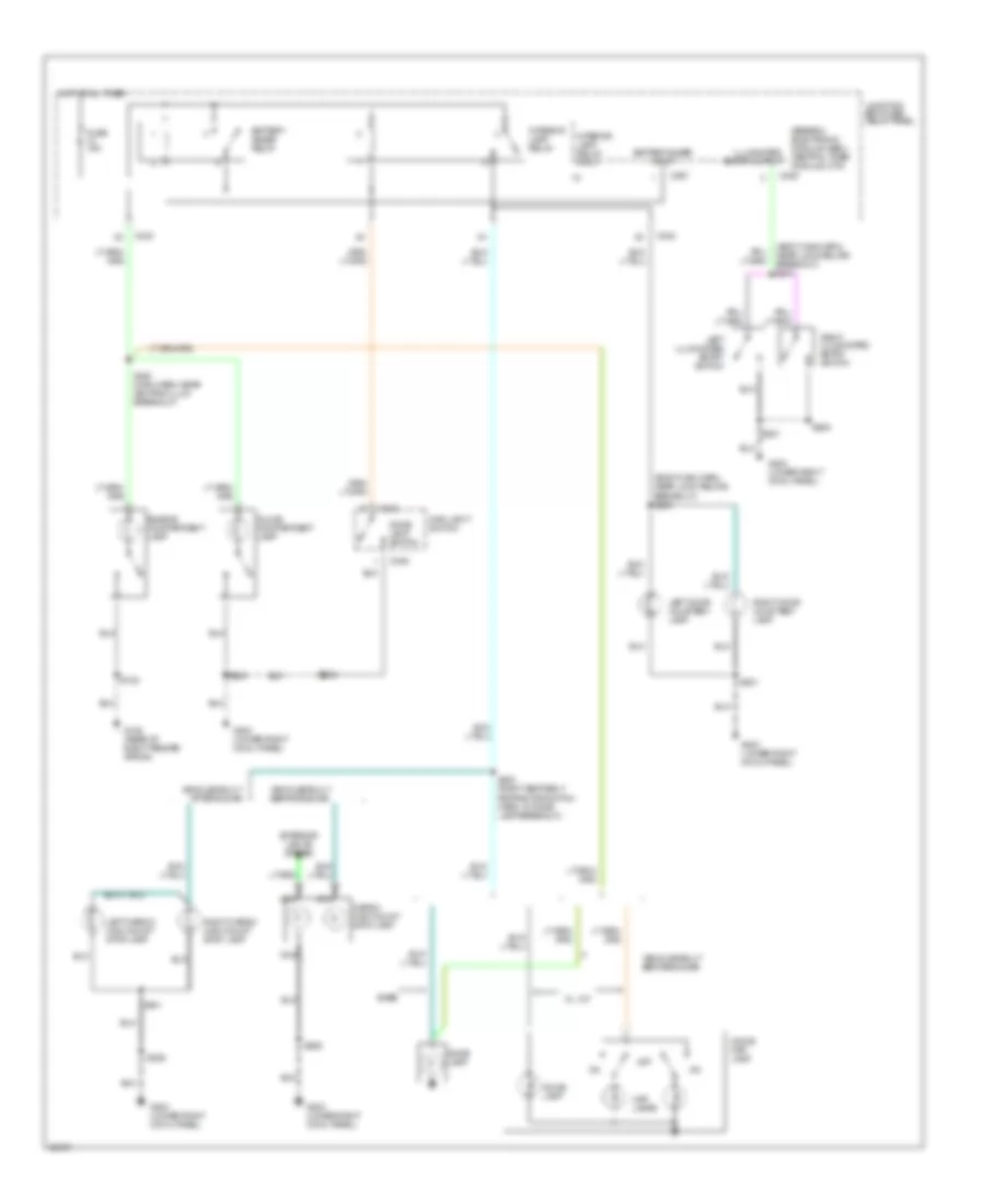 https://portal-diagnostov.com/license.html
Automotive Electricians Portal FZCO
Automotive Electricians Portal FZCO
https://portal-diagnostov.com/license.html
https://portal-diagnostov.com/license.html
Automotive Electricians Portal FZCO
Automotive Electricians Portal FZCOList of elements for Courtesy Lamp Wiring Diagram for Ford Pickup F150 1997:
- g105 (rear of right fender apron)
- s240 (main harn, near ashtray illum breakout)
- (body main harn, near lock relays breakout) s239
- (body main harn, near lock relays breakout) s241
- Base
- Battery saver input
- Battery saver relay
- C239
- C242
- C243
- C245
- C246
- C267
- Cargo/ high mount stop lamp
- Dome lamp
- Dome lamp switch
- Dome/ map lamp
- Engine compartment lamp
- Exterior lights system
- Fuse 15a
- G203 (lower right cowl panel)
- Generic electronic module (gem)/ central timer module (ctm)
- Glove compartment lamp
- Hot at all times
- Illuminated entry output
- Interior lamp relay
- Interior lamp relay input
- Junction box fuse/ relay panel
- Left cargo/ high mount stop lamp
- Left door courtesy lamp
- Left illuminated entry switch
- Main light switch
- Map lamps
- Nca
- Off
- Right cargo/ high mount stop lamp
- Right door courtesy lamp
- Right illuminated entry switch
- S102
- S200
- S204
- S206
- S300 (right seat belt retractor switch harn, in dome lamp breakout)
- S501
- S600
- S911
- Vehicles built after 6/24/96
- Vehicles built before 6/24/96
- Xl, xlt
Instrument Illumination Wiring Diagram for Ford Pickup F150 1997
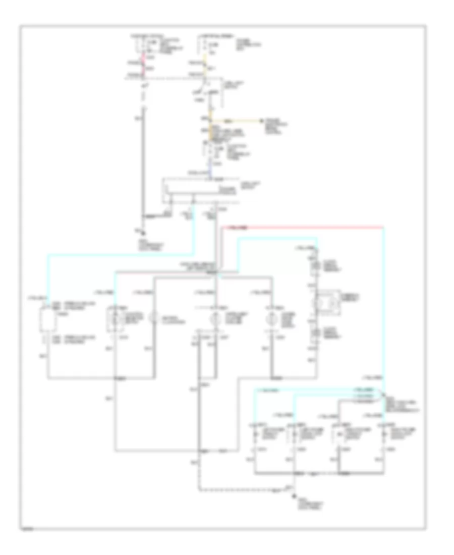 https://portal-diagnostov.com/license.html
Automotive Electricians Portal FZCO
Automotive Electricians Portal FZCO
https://portal-diagnostov.com/license.html
https://portal-diagnostov.com/license.html
Automotive Electricians Portal FZCO
Automotive Electricians Portal FZCOList of elements for Instrument Illumination Wiring Diagram for Ford Pickup F150 1997:
- (main harn, behind left side of i/p) s242
- (premium sound)
- (standard)
- 4wheel drive mode switch
- Ashtray illumination
- C219
- C230
- C236
- C237
- C242
- C245
- C246
- C255
- C262
- C508
- C510
- C608
- C609
- Clock- spring assembly
- Dimmer module
- Function selector switch
- Fuse 15a
- Fuse 5a
- G203 (lower right cowl panel)
- Head
- Hot at all times
- Hotin acc or run
- Instrument cluster (6 bulbs)
- Junction box fuse/relay panel
- Left power door lock switch
- Left power window switch
- Main light switch
- Nca
- Off
- Park
- Power distribution box
- Radio
- Right power door lock switch
- Right power window switch
- S201
- S202
- S203
- S204
- S211
- S223
- S224 (main harn, near main light switch breakout) c243
- S243 (body main harn, near lock relays breakout)
- S500
- S502
- Steering assembly
- Trailer electronic brake control
POWER DISTRIBUTION
Power Distribution Wiring Diagram (1 of 4) for Ford Pickup F150 1997
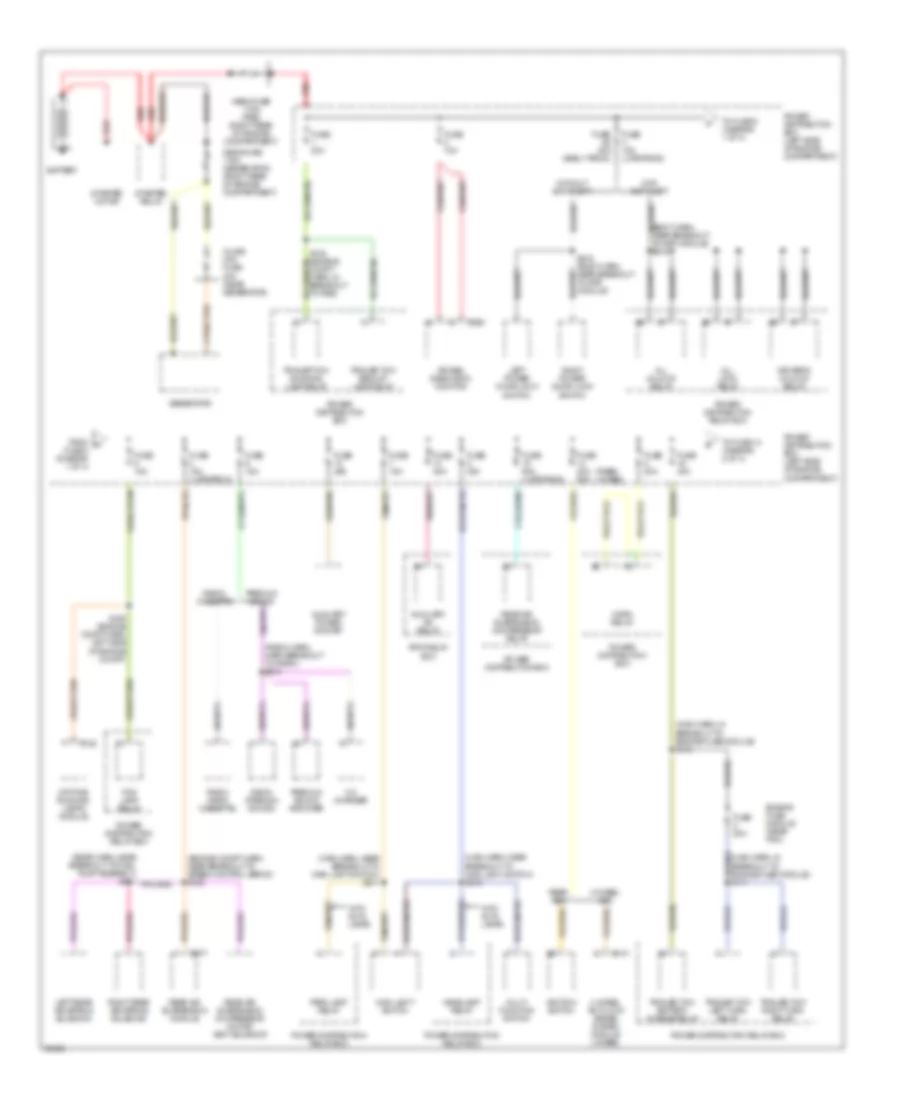 https://portal-diagnostov.com/license.html
Automotive Electricians Portal FZCO
Automotive Electricians Portal FZCO
https://portal-diagnostov.com/license.html
https://portal-diagnostov.com/license.html
Automotive Electricians Portal FZCO
Automotive Electricians Portal FZCOList of elements for Power Distribution Wiring Diagram (1 of 4) for Ford Pickup F150 1997:
- (body harn, near breakout to rap module) s216
- (engine compt harn, near breakout to speed control servo) s152
- (main harn, in breakout to engine fuse module) s110
- (main harn, near breakout to main light switch) s211
- (main harn, near breakout to main light switch) s212
- (rabs) (4wabs)
- (radio harn, harn breakout to radio) s210
- 4 wheel abs
- 4 wheel anti-lock brake system module (4wabs)
- Air bag diagnostic monitor
- All lock relay
- All unlock relay
- Auxiliary a/c relay
- Auxiliary power socket
- Battery
- C142
- C147
- C209
- C277
- Cd changer
- Daytime running lamps module
- Driver's unlock relay
- Engine fuse module (near pdc)
- Fog lamp relay
- From a fuse 3 (diagram 1 of 4)
- Fuse 10a
- Fuse 15a
- Fuse 15a (late prod)
- Fuse 20a
- Fuse 20a (early prod)
- Fuse 20a 60a
- Fuse 25a
- Fuse 30a
- Fuse 40a
- Fuse 50a (late prod)
- Generator
- Headlamp relay
- Horn relay
- Ignition switch
- Inline mini fuse 20a (near generator)
- Left power door lock switch
- Left rear air spring solenoid
- Main light switch
- Mega fuse 175a (generator) (right rear of engine compartment)
- Mega fuse 175a (pdb) (right rear of engine compartment)
- Multi- function switch
- Park lamp relay
- Power distribution box
- Power distribution box (left side of engine compartment)
- Power distribution relay box
- Premium sound amplifier
- Radio (am/fm cassette)
- Radio (premium sound)
- Radio/ cassette
- Rear abs
- Rear air suspension compressor motor/ vent solenoid
- Rear air suspension compressor relay
- Rear air suspension module
- Red
- Right power door lock switch
- Right rear air spring solenoid
- Rpo relay box
- S108 (engine compt harn, in breakout to pdb)
- S109 (engine compt harn left side of engine compt)
- S216 (body harn, near breakout to rap module)
- Starter motor
- Starter relay
- To fuse 14 (diagram 2 of 4)
- To fuse 9 (diagram 1 of 4)
- Trailer tow backup lamp relay
- Trailer tow battery charge relay
- Trailer tow left turn relay
- Trailer tow right turn relay
- Trailer tow running lamp relay
- With anti-theft
- With auto lamps
- Without anti-theft
Power Distribution Wiring Diagram (2 of 4) for Ford Pickup F150 1997
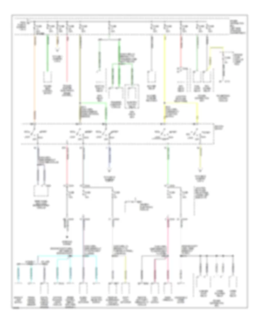 https://portal-diagnostov.com/license.html
Automotive Electricians Portal FZCO
Automotive Electricians Portal FZCO
https://portal-diagnostov.com/license.html
https://portal-diagnostov.com/license.html
Automotive Electricians Portal FZCO
Automotive Electricians Portal FZCOList of elements for Power Distribution Wiring Diagram (2 of 4) for Ford Pickup F150 1997:
- (engine compt harn, left rear of engine compt) s112
- (engine compt harn, near breakout to pdc) s113
- (main harn, in breakout to fuse relay panel) (late prod) s265
- (main harn, near breakout to instrument cluster) s222
- (main harn, near breakout to instrument cluster) s223
- (main harn, near breakout to rwabs module) s217
- A/t
- A/t early prod
- A/t late prod
- Acc
- Acc delay relay
- Backup lamp switch
- Blend door actuator
- Blower relay
- Blower/ flasher relay box
- C142
- C174
- C222
- C242
- C243
- C256
- C267
- C277
- Daytime running lamps module
- Digital trans- mission range sensor
- Electric clutch relay
- Engine fuse module (near pdc)
- From b fuse 16 (diagram 1 of 4)
- Fuel pump relay
- Function selector switch
- Fuse 15a
- Fuse 20a
- Fuse 20a (rwabs)
- Fuse 30a
- Fuse 40a
- Fuse 50a
- Fuse 5a
- Generic electronic module
- Ignition switch
- Junction box fuse/ relay panel
- Junction box fuse/ relay panel (under left side of i/p)
- Lock
- M/t
- Main light switch
- Off
- Pcm power relay
- Power distribution box
- Power distribution box (left side of engine compartment)
- Power seat control switch
- Powertrain control module
- Radio (premium)
- Rear air suspension module (late prod)
- Rear wheel anti-lock brakes system module
- Red
- Remote anti-theft personality module
- Rpo relay box
- Run
- S214 (main harn, near steering wheel rotation sensor)
- S215 (main harn, in breakout to ignition switch)
- Shift lock actuator
- Shift on the fly relay
- Speed control servo/ amplifier assembly
- Start
- Starting system
- To fuse 1 (diagram 3 of 4)
- To fuse 19 (diagram 3 of 4)
- To fuse 22 (diagram 4 of 4)
- Trailer adapter (electronic brake control)
- Trans- mission range sensor
- Transfer case shift module
- Washer pump relay
- Windshield wiper motor
- Wiper hi/lo relay
- Wiper run/park relay
Power Distribution Wiring Diagram (3 of 4) for Ford Pickup F150 1997
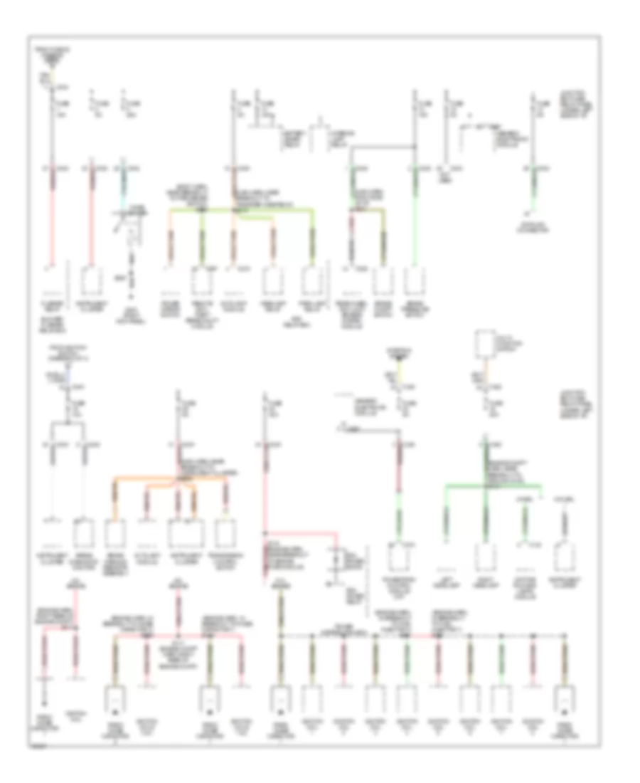 https://portal-diagnostov.com/license.html
Automotive Electricians Portal FZCO
Automotive Electricians Portal FZCO
https://portal-diagnostov.com/license.html
https://portal-diagnostov.com/license.html
Automotive Electricians Portal FZCO
Automotive Electricians Portal FZCOList of elements for Power Distribution Wiring Diagram (3 of 4) for Ford Pickup F150 1997:
- (body harn, near breakout to park brake switch) s220
- (engine compt harn, near breakout to ground g108) s114
- (engine harn, in breakout to fuel injector 3) s161
- (engine harn, in breakout to fuel injector 7) s162
- (engine harn, in breakout to noise capacitor 1) s118
- (engine harn, in breakout to noise capacitor 2) s119
- (engine harn, right rear of engine compt) s117
- (main harn, near breakout to instrument cluster) s225
- (main harn, near breakout to transfer case relay) s219
- (main harn, right side of i/p) s221
- 4.2l engine
- 4.6l engine
- 5.4l engine
- Airbag diagnostic monitor
- Autolamp module
- Battery saver relay
- Blower/ flasher relay box
- Brake on/off switch
- Brake pressure switch
- Brake warning resistor assembly
- C142
- C174
- C216
- C222
- C242
- C243
- C257
- C267
- Cigar lighter
- Datalink connector
- Daytime running lamps module
- Flasher relay
- From fuse 22 (diagram 2 of 4) c
- From ignition switch (diagram 2 of 4)
- Fuse 10a
- Fuse 15a
- Fuse 20a
- Fuse 25a
- Fuse 30a
- Fuse 5a
- G203 (right kick panel)
- Generic electronic module
- Headlamp relay
- Ignition coil
- Ignition coils 1 & 2
- Ignition coils 3 & 4
- Instrument cluster
- Interior lamp relay
- Junction box fuse/ relay panel (under left side of i/p)
- Left headlamp
- Multi- function switch
- Not used
- Park lamp relay
- Pcm power diode
- Pcm power relay
- Power distribution box
- Power mirror switch
- Powertrain control module (m/t)
- Radio noise capacitor
- Rear wheel anti-lock brakes system module
- Red
- Remote anti- theft personality module
- Right headlamp
- Rpo relay box
- S116 (engine harn, near breakout to engine fuse module)
- S117 (engine compt harn, right rear of engine compt)
- S205
- Starting system
- Transmission control switch
- W/ drl
- W/o drl
Power Distribution Wiring Diagram (4 of 4) for Ford Pickup F150 1997
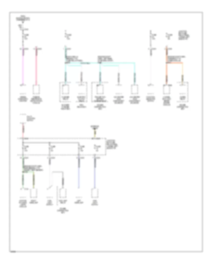 https://portal-diagnostov.com/license.html
Automotive Electricians Portal FZCO
Automotive Electricians Portal FZCO
https://portal-diagnostov.com/license.html
https://portal-diagnostov.com/license.html
Automotive Electricians Portal FZCO
Automotive Electricians Portal FZCOList of elements for Power Distribution Wiring Diagram (4 of 4) for Ford Pickup F150 1997:
- (engine compt harn, in breakout to 4wabs module) s121
- (engine compt harn, left rear of engine compt) s120
- (engine compt harn, near breakout to ambient temp sensor) s122
- (main harn, in breakout to fuse/ relay panel) s228
- 4 wheel anti-lock brake system module
- 4wabs relay
- 4x2 center axle disconnect solenoid
- 4x4 center axle disconnect solenoid
- Airbag diagnostic monitor
- Blower/ flasher relay box
- C142
- C146
- C243
- C243 tan/red
- Daytime running lamps module
- Electric clutch relay
- Exterior lights
- Flasher relay
- Fog lamp relay
- From ignition switch (diagram 2 of 4)
- Function selector switch
- Fuse 10a
- Fuse 5a
- Junction box fuse/ relay panel (under left side of i/p)
- Left headlamp
- Main light switch
- Multi- function switch
- Passive restraints de-activation module
- Power distribution box
- Right headlamp
- Rpo relay box
- Tan/red
- Trailer tow battery charge relay
POWER DOOR LOCKS
Door Lock Wiring Diagram for Ford Pickup F150 1997
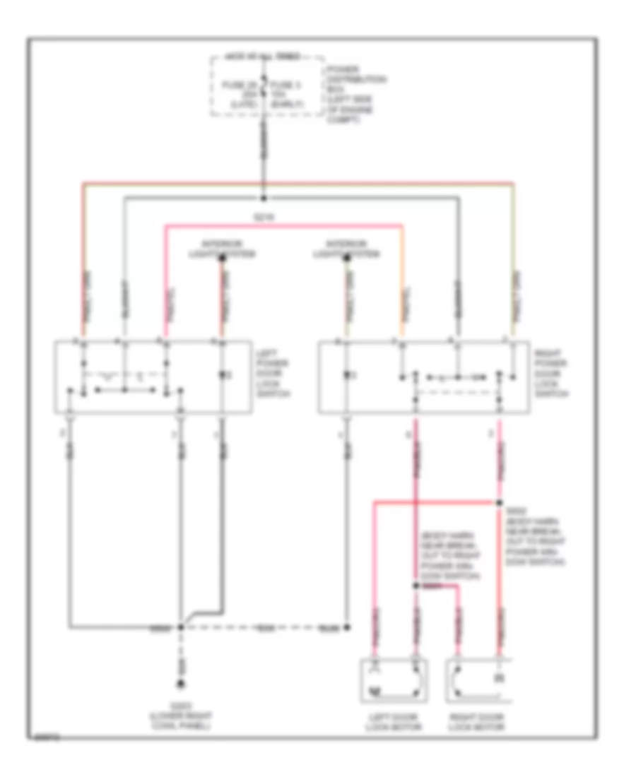 https://portal-diagnostov.com/license.html
Automotive Electricians Portal FZCO
Automotive Electricians Portal FZCO
https://portal-diagnostov.com/license.html
https://portal-diagnostov.com/license.html
Automotive Electricians Portal FZCO
Automotive Electricians Portal FZCOList of elements for Door Lock Wiring Diagram for Ford Pickup F150 1997:
- (body harn near break- out to right power win- dow switch) s601
- Fuse 26 20a (late)
- Fuse 3 15a (early)
- G203 (lower right cowl panel)
- Hot at all times
- Interior lights system
- Left door lock motor
- Left power door lock switch
- Power distribution box (left side of engine compt)
- Right door lock motor
- Right power door lock switch
- S216
- S500
- S600
- S602 (body harn near break- out to right power win- dow switch)
Keyless Entry Wiring Diagram for Ford Pickup F150 1997
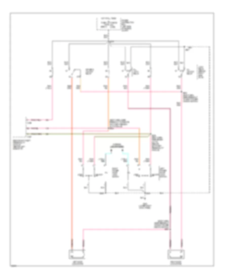 https://portal-diagnostov.com/license.html
Automotive Electricians Portal FZCO
Automotive Electricians Portal FZCO
https://portal-diagnostov.com/license.html
https://portal-diagnostov.com/license.html
Automotive Electricians Portal FZCO
Automotive Electricians Portal FZCOList of elements for Keyless Entry Wiring Diagram for Ford Pickup F150 1997:
- (body harn, near breakout to remote anti-theft person- ality module) s234
- (body harn, near breakout to right power window switch) s601
- 87a
- All lock relay
- All unlock relay
- C256
- C257
- Driver's unlock relay
- Fuse 26 20a (late)
- Fuse 3 15a (early)
- G203 (lower right cowl panel)
- Hot at all times
- Interior lights system
- Left door lock motor
- Left power door lock switch
- Lock
- Lock relay (behind right side of i/p)
- Power distribution box (left side of engine compt)
- Remote anti-theft personality module (behind left side of i/p)
- Right door lock motor
- Right power door lock switch
- S216
- S235 (body harn, near break- out to remote anti-theft personality module)
- S500
- S501
- S600
- S602 (body harn, near breakout to right power window switch)
- Unlock
POWER MIRRORS
Power Mirror Wiring Diagram for Ford Pickup F150 1997
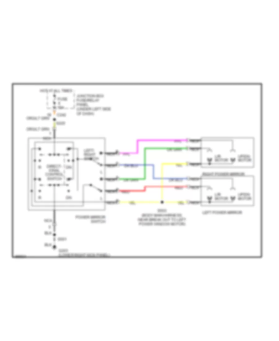 https://portal-diagnostov.com/license.html
Automotive Electricians Portal FZCO
Automotive Electricians Portal FZCO
https://portal-diagnostov.com/license.html
https://portal-diagnostov.com/license.html
Automotive Electricians Portal FZCO
Automotive Electricians Portal FZCOList of elements for Power Mirror Wiring Diagram for Ford Pickup F150 1997:
- C242
- Direct- ional control switch
- Fuse 15a
- G203 (lower right kick panel)
- Hot at all times
- Junction box fuse/relay panel (under left side of dash)
- L/r motor
- Left power mirror
- Left/ right switch
- Nca
- Power mirror switch
- Red
- Right power mirror
- S220
- S501
- S503 (body main harness, near break out to left power window motor)
- Up/dn motor
POWER SEATS
Power Seat Wiring Diagram for Ford Pickup F150 1997
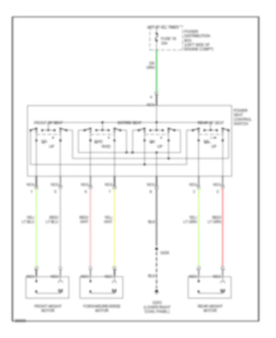 https://portal-diagnostov.com/license.html
Automotive Electricians Portal FZCO
Automotive Electricians Portal FZCO
https://portal-diagnostov.com/license.html
https://portal-diagnostov.com/license.html
Automotive Electricians Portal FZCO
Automotive Electricians Portal FZCOList of elements for Power Seat Wiring Diagram for Ford Pickup F150 1997:
- Entire seat
- Forward/reverse motor
- Front height motor
- Front of seat
- Fuse 18 30a
- Fwd
- G203 (lower right cowl panel)
- Hot at all times
- Nca
- Power distribution box (left side of engine compt)
- Power seat control switch
- Rear height motor
- Rear of seat
- Rwd
- S206
POWER WINDOWS
Power Window Wiring Diagram for Ford Pickup F150 1997
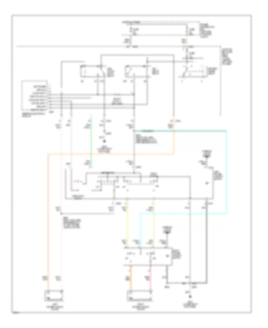 https://portal-diagnostov.com/license.html
Automotive Electricians Portal FZCO
Automotive Electricians Portal FZCO
https://portal-diagnostov.com/license.html
https://portal-diagnostov.com/license.html
Automotive Electricians Portal FZCO
Automotive Electricians Portal FZCOList of elements for Power Window Wiring Diagram for Ford Pickup F150 1997:
- 87a
- Acc delay relay
- Batt saver
- Battery saver relay
- C242
- C243
- C267
- C509
- C510
- Down sw input
- Fuse 15a
- Fuse 30a
- Fuse 50a
- G203 (lower right kick panel)
- Generic electronic module
- Ground
- Hot at all times
- Interior lights system
- Junction box fuse/ relay panel (under left side of dash)
- Left power window motor
- Left power window switch
- Left switch
- One tch dn hi
- One tch dn lo
- One touch down
- One touch down relay
- Otd sw input
- Power distribution box (left side of engine compt)
- Right power window motor
- Right power window switch
- Right switch
- S205
- S248 (body main harn, near breakout to park brake switch)
- S500
- S502 (body main harn, near breakout to left power window motor)
- S600
- Shunt (0.015 +/- 0.001 ohm)
- Up sw input
RADIO
Base Radio for Ford Pickup F150 1997
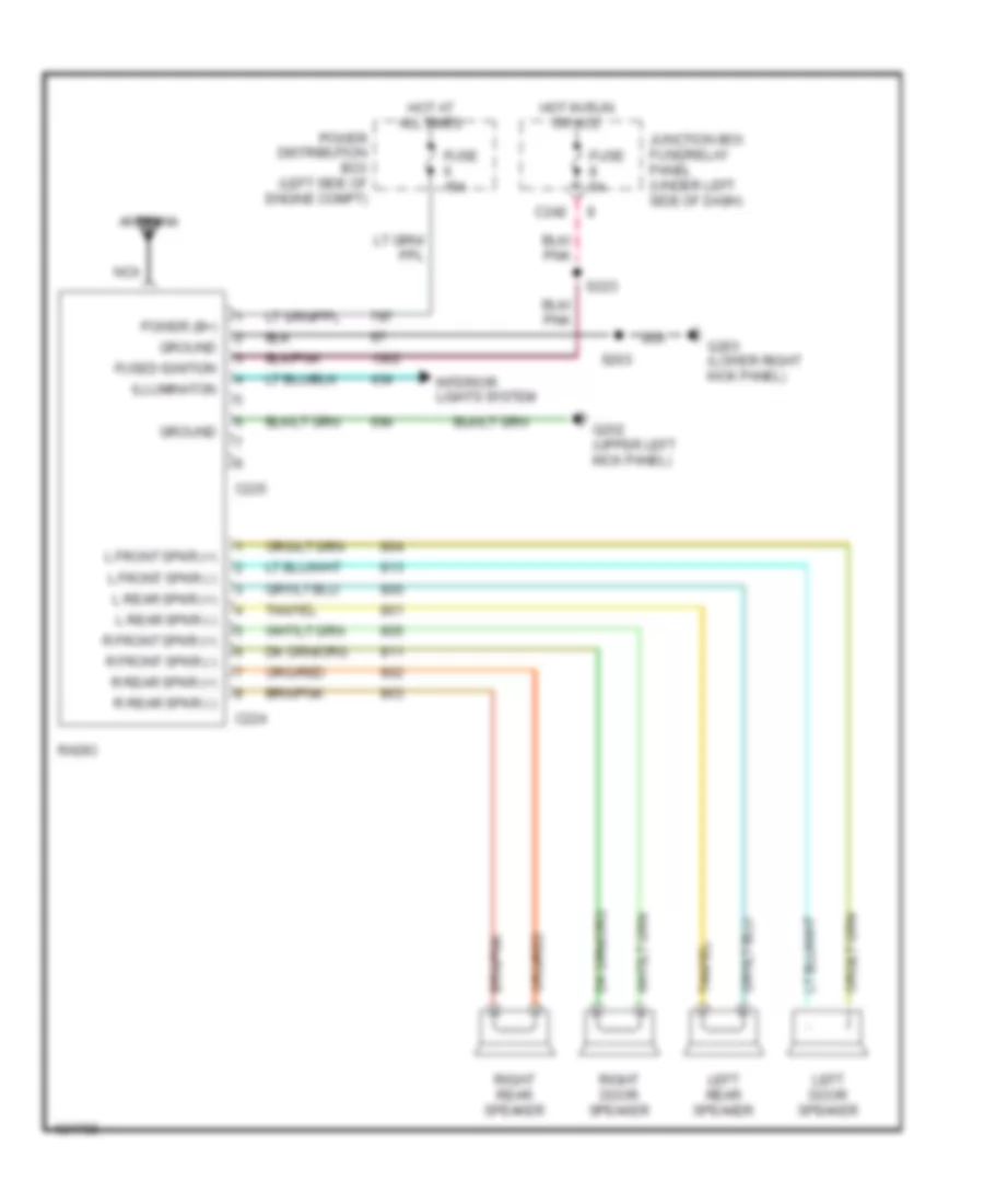 https://portal-diagnostov.com/license.html
Automotive Electricians Portal FZCO
Automotive Electricians Portal FZCO
https://portal-diagnostov.com/license.html
https://portal-diagnostov.com/license.html
Automotive Electricians Portal FZCO
Automotive Electricians Portal FZCOList of elements for Base Radio for Ford Pickup F150 1997:
- Antenna
- C224
- C225
- C242
- Fuse 15a
- Fuse 5a
- Fused ignition
- G202 (upper left kick panel)
- G203 (lower right kick panel)
- Ground
- Hot at all times
- Hot in run or acc
- Illuminaton
- Interior lights system
- Junction box fuse/relay panel (under left side of dash)
- L front spkr (+)
- L front spkr (-)
- L rear spkr (+)
- L rear spkr (-)
- Left door speaker
- Left rear speaker
- Nca
- Power (b+)
- Power distribution box (left side of engine compt)
- R front spkr (+)
- R front spkr (-)
- R rear spkr (+)
- R rear spkr (-)
- Radio
- Right door speaker
- Right rear speaker
- S203
- S223
Premium Sound Radio Wiring Diagram for Ford Pickup F150 1997
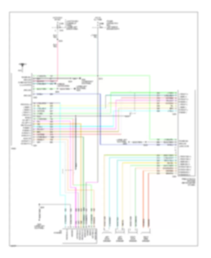 https://portal-diagnostov.com/license.html
Automotive Electricians Portal FZCO
Automotive Electricians Portal FZCO
https://portal-diagnostov.com/license.html
https://portal-diagnostov.com/license.html
Automotive Electricians Portal FZCO
Automotive Electricians Portal FZCOList of elements for Premium Sound Radio Wiring Diagram for Ford Pickup F150 1997:
- (upper left kick panel) g202
- Antenna
- Audio on
- C242
- C261
- C262
- C263
- C264
- Cd changer
- Cd left (+)
- Cd left (-)
- Cd right (+)
- Cd right (-)
- Fuse 5a
- Fuse fuse 15a
- Fused ignition
- G202 (upper left kick panel)
- G203 (lower right kick panel)
- Ground
- Hot at all times
- Hot in run or acc
- Illulminaton
- Interior lights system
- Junction box fuse/relay panel) (under left side of dash)
- L front (+)
- L front (-)
- L front sig (+)
- L front sig (-)
- L rear (+)
- L rear (-)
- L rear sig (+)
- L rear sig (-)
- Left door speaker
- Left rear speaker
- Left sig (+)
- Left sig (-)
- Logic mute
- Nca
- Power
- Power (b+)
- Power distribution box (left side of engine compt)
- Premium sound amplifier (behind center of dash)
- Protocal b
- Protocol a
- Protocol b
- R front (+)
- R front (-)
- R front sig (+)
- R front sig (-)
- R rear (+)
- R rear (-)
- R rear sig (+)
- R rear sig (-)
- Radio
- Right door speaker
- Right rear speaker
- Right sig (+)
- Right sig (-)
- S203
- S209
- S210
- S223
- Shield
- Tan
SHIFT INTERLOCKS
Shift Interlock Wiring Diagram for Ford Pickup F150 1997
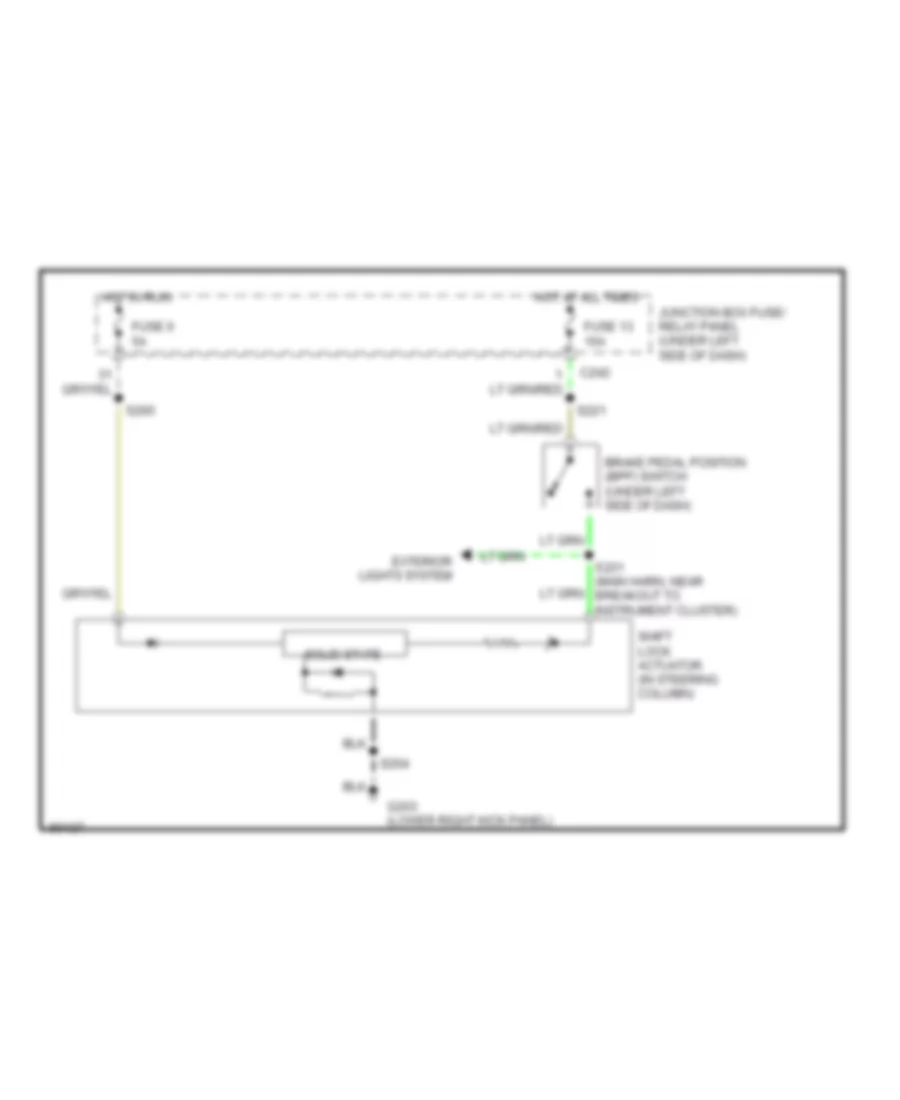 https://portal-diagnostov.com/license.html
Automotive Electricians Portal FZCO
Automotive Electricians Portal FZCO
https://portal-diagnostov.com/license.html
https://portal-diagnostov.com/license.html
Automotive Electricians Portal FZCO
Automotive Electricians Portal FZCOList of elements for Shift Interlock Wiring Diagram for Ford Pickup F150 1997:
- Brake pedal position (bpp) switch (under left side of dash)
- C242
- Exterior lights system
- Fuse 13 15a
- Fuse 6 5a
- G203 (lower right kick panel)
- Hot at all times
- Hot in run
- Junction box fuse/ relay panel (under left side of dash)
- S204
- S221
- S231 (main harn, near breakout to instrument cluster)
- S265
- Shift lock actuator (in steering column)
- Solid state
STARTING/CHARGING
Charging Wiring Diagram for Ford Pickup F150 1997
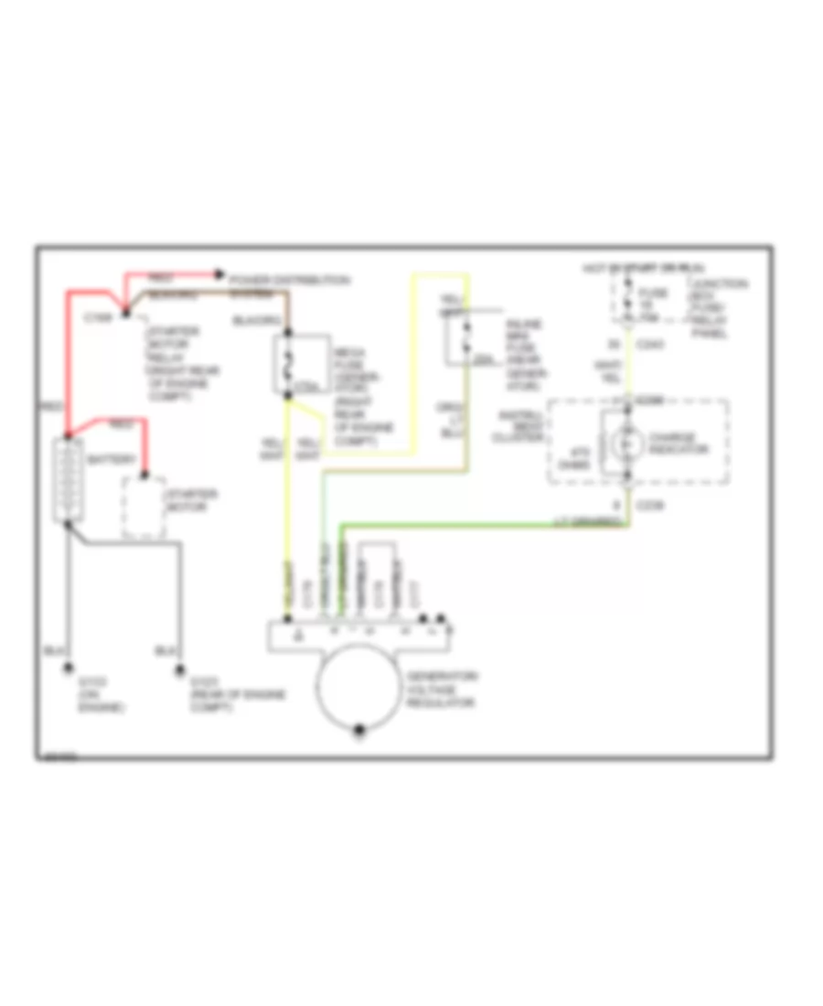 https://portal-diagnostov.com/license.html
Automotive Electricians Portal FZCO
Automotive Electricians Portal FZCO
https://portal-diagnostov.com/license.html
https://portal-diagnostov.com/license.html
Automotive Electricians Portal FZCO
Automotive Electricians Portal FZCOList of elements for Charging Wiring Diagram for Ford Pickup F150 1997:
- 175a
- 20a
- Battery
- C166
- C176
- C177
- C178
- C238
- C243
- Charge indicator
- Fuse 10a
- G123 (rear of engine compt)
- G133 (on engine)
- Generator/ voltage regulator
- Hot in start or run
- Inline mini fuse (near gener- ator)
- Instru- ment cluster
- Junction box fuse/ relay panel
- Mega fuse (gener- ator) (right rear of engine compt)
- Ohms
- Power distribution system
- Red
- Starter motor
- Starter motor relay (right rear of engine compt)
Starting Wiring Diagram, A/T for Ford Pickup F150 1997
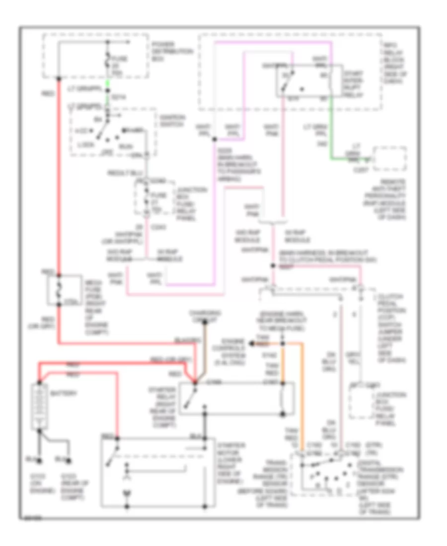 https://portal-diagnostov.com/license.html
Automotive Electricians Portal FZCO
Automotive Electricians Portal FZCO
https://portal-diagnostov.com/license.html
https://portal-diagnostov.com/license.html
Automotive Electricians Portal FZCO
Automotive Electricians Portal FZCOList of elements for Starting Wiring Diagram, A/T for Ford Pickup F150 1997:
- (dtr)
- (engine harn, near breakout to mega fuse)
- (main harness, in breakout to clutch pedal position sw) s227
- (tr)
- 175a
- 87a
- Acc
- Battery
- C166
- C167
- C182
- C192
- C243
- C257
- Charging circuit
- Clutch pedal position (ccp) switch jumper (under left side of dash)
- Digital transmission range (dtr) sensor (after 6/24/ 96) (left side of trans)
- Engine controls system (5.4l cng)
- Fuse 15a
- Fuse 50a
- G123 (rear of engine compt)
- G133 (on engine)
- Ignition switch
- Junction box fuse/ relay panel
- Lock
- Mega fuse (pdb) (right rear of engine compt)
- Off
- Power distribution box
- Red
- Remote anti-theft personality (rap) module (left side of dash)
- Rpo relay block (right side of dash)
- Run
- S142
- S214
- S226 (main harn, in breakout to passngr's airbag)
- Sta
- Start
- Start inter- rupt relay
- Starter motor (lower right side of engine)
- Starter relay (right rear of engine compt)
- Tan/ red
- Trans- mission range (tr) sensor (before 6/24/96) (left side of trans)
- W/ rap module
- W/o rap module
Starting Wiring Diagram, M/T for Ford Pickup F150 1997
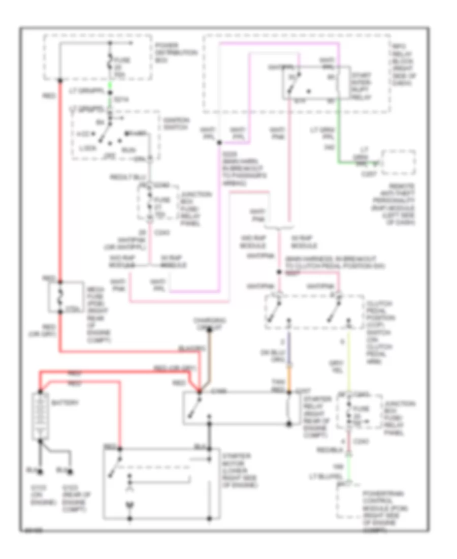 https://portal-diagnostov.com/license.html
Automotive Electricians Portal FZCO
Automotive Electricians Portal FZCO
https://portal-diagnostov.com/license.html
https://portal-diagnostov.com/license.html
Automotive Electricians Portal FZCO
Automotive Electricians Portal FZCOList of elements for Starting Wiring Diagram, M/T for Ford Pickup F150 1997:
- (main harness, in breakout to clutch pedal position sw) s227
- 175a
- 87a
- Acc
- Battery
- C166
- C167
- C243
- C257
- Charging circuit
- Clutch pedal position (ccp) switch (on clutch pedal arm)
- Fuse 15a
- Fuse 50a
- Fuse 5a
- G123 (rear of engine compt)
- G133 (on engine)
- Ignition switch
- Junction box fuse/ relay panel
- Lock
- Mega fuse (pdb) (right rear of engine compt)
- Off
- Power distribution box
- Powertrain control module (pcm) (right side of engine compt)
- Red
- Remote anti-theft personality (rap) module (left side of dash)
- Rpo relay block (right side of dash)
- Run
- S214
- S226 (main harn, in breakout to passngr's airbag)
- Sta
- Start
- Start inter- rupt relay
- Starter motor (lower right side of engine)
- Starter relay (right rear of engine compt)
- Tan/ red
- W/ rap module
- W/o rap module
SUPPLEMENTAL RESTRAINTS
Supplemental Restraint Wiring Diagram for Ford Pickup F150 1997
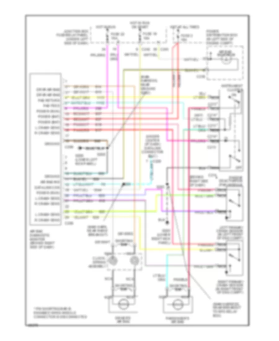 https://portal-diagnostov.com/license.html
Automotive Electricians Portal FZCO
Automotive Electricians Portal FZCO
https://portal-diagnostov.com/license.html
https://portal-diagnostov.com/license.html
Automotive Electricians Portal FZCO
Automotive Electricians Portal FZCOList of elements for Supplemental Restraint Wiring Diagram for Ford Pickup F150 1997:
- (behind right side of dash)
- (main harn, near radio breakout)
- (main harness, near breakout to rpo relay box)
- (main harness, near ground g202)
- (under center of dash) data link connector (dlc)
- * c213
- * c214
- * pin shorting bar is engaged when module connector is disconnected
- Air bag diagnostic monitor (behind right side of dash)
- Air bag ind
- Air bag indicator
- C208
- C209
- C213
- C214
- C238
- C242
- C243
- Clock- spring assembly
- Data link con
- Driver's air bag
- Drvr air bag
- Fuse 19 10a
- Fuse 2 10a
- Fuse 22 10a
- G200 (lower left kick panel)
- G203 (lower right kick panel)
- Ground
- Hot at all times
- Hot in run
- Hot in run or start
- Instrument cluster
- Junction box fuse/relay panel (under left side of dash)
- L crash sens
- Left primary crash sensor (in left front of eng compt)
- Nca
- Off
- Pad feed
- Pad return
- Passenger's air bag
- Passive deactivation (pad) module
- Power (bat)
- Power (run)
- Power distribution box (in left side of engine compt)
- R crash sens
- Right primary crash sensor (in right front of eng compt)
- S203
- S208
- S229
- Shorting bar
TRANSMISSION
4.2L
4.2L, Transmission Wiring Diagram, 4R70W for Ford Pickup F150 1997
 https://portal-diagnostov.com/license.html
Automotive Electricians Portal FZCO
Automotive Electricians Portal FZCO
https://portal-diagnostov.com/license.html
https://portal-diagnostov.com/license.html
Automotive Electricians Portal FZCO
Automotive Electricians Portal FZCOList of elements for 4.2L, Transmission Wiring Diagram, 4R70W for Ford Pickup F150 1997:
- (backup lamp sw to rear lamp harn, right rear of engine compt)
- (bare)
- (engine ctrl harn, near breakout to pcm)
- (engine ctrl harn, near breakout to pdb)
- (engine ctrl harn, near breakout to starter motor relay)
- (engine ctrl harn, near breakout to vapor mgt valve)
- (engine ctrl harn, near breakout to vapor mgt valve) s143
- (engine ctrl harn, right rear of engine compt)
- (fuel charge harn, near breakout to fuel inj 4)
- (left side of engine compt) power distribution box
- (left side of transmission) transmission range (tr) sensor
- 4r70w transmission (mounted under center of vehicle)
- Autolamp module, instr cluster, brake warning resistor assy
- Boo
- Brake on/off (boo) switch (under left side of dash)
- Brake pressure switch
- C174
- C236
- Case gnd
- Data
- Data link connector (dlc) (partial) (under left side of dash)
- Digital transmission range sensor (left side of transmission)
- Dlc (+)
- Dlc (-)
- Ect
- Electronic pressure control (epc) solenoid
- Engine controls system
- Engine coolant temperature (ect) sensor (top front of engine)
- Engine fuse module (in engine compt, near pdb)
- Epc
- Fuse 13 15a
- Fuse 24 30a
- Fuse 29 5a
- Fuse 30 30a
- Fuse 5a
- G108 (left front radiator support)
- G121 (rear of engine compartment)
- G200 (lower left kick panel)
- Hot at all times
- Hot in run
- Hot in start or run
- Iat
- Ignition coils, radio noise capacitor
- Instrument cluster
- Intake air temperature sensor (on intake manifold)
- Junction box fuse/ relay panel (under left side of dash)
- Kapwr
- Malfunction indicator lamp (mil) (check engine)
- Mil
- N d
- O/d off ind
- Oss
- Output shaft speed sensor (left side of transmission)
- Pcm power diode 2
- Pcm power relay
- Power distribution box (left side of engine compt)
- Powertrain control module (pcm) (right side of engine compt)
- Pwr gnd
- R p
- Rear abs control module
- Red
- S100
- S101
- S106
- S107
- S116
- S127
- S128
- S135
- S137
- S138
- S140
- S141
- S144
- S221
- S225
- Shift solenoids (ss)
- Sig rtn
- Ss1
- Ss2
- Tcc
- Tcil
- Tcs
- Tft
- Throttle position (tp) sensor (on throttle body)
- Torque converter clutch (tcc) solenoid
- Tr1
- Tr2
- Tr3
- Tr4
- Transmission control switch (tcs) (end of transmission selector lever)
- Transmission fluid temperature sensor
- Vehicle speed sensor (vss) (left rear of transmission)
- Vpwr
- Vref
- Vss
- W/ dtr sensor
- W/ tr sensor
Transfer Case Wiring Diagram, Electronic for Ford Pickup F150 1997
 https://portal-diagnostov.com/license.html
Automotive Electricians Portal FZCO
Automotive Electricians Portal FZCO
https://portal-diagnostov.com/license.html
https://portal-diagnostov.com/license.html
Automotive Electricians Portal FZCO
Automotive Electricians Portal FZCOList of elements for Transfer Case Wiring Diagram, Electronic for Ford Pickup F150 1997:
- (engine ctrl harn, near breakout to vapor mgt valve) s143
- (lower right kick panel) g203
- (main harn, near breakout to gem)
- (right side of engine compt) 4x2 center axle disconnect solenoid
- (right side of engine compt) 4x4 center axle disconnect solenoid
- (under left side of dash) junction box fuse/ relay panel
- 1.1k ohms
- 3.9k ohms
- 4 wheel drive mode switch
- 4wd low out
- 4wd output
- 4x2 sol
- 4x4 high ind
- 4x4 high range indicator
- 4x4 low ind
- 4x4 low range indicator
- 4x4 mode sw
- 4x4 sol
- Anti-lock brake module
- Apron) g105
- Autolamp mod, tcs switch, brake warning resistor assy
- Bpp sw input
- Brake pedal position switch (under left side of dash)
- Brake pressure switch
- C174
- C236
- C238
- C239
- C241
- C242
- C243
- Digital transmission range (dtr) sensor (all others) (left side of transmission)
- Early 1997 all others
- Flasher relay
- Fuse 13 15a
- Fuse 17 30a
- Fuse 23 10a
- Fuse 29 5a
- G108 (top front radiator support)
- G200 (lower left kick panel)
- Generic electronic module (gem) (behind left side of dash)
- H2l
- H2l rly ctrl
- Hot at all times
- Hot in run or start
- Illumination
- Instrument cluster
- Interior lights (instrument illumination)
- Junction box fuse/ relay panel (under left side of dash)
- L2h
- L2h rly ctrl
- Magnetic clutch
- Neutral sw in
- Not used
- Ohms
- Power distribution box (left side of engine compt)
- Powertrain control module (right side of engine compt)
- Rear abs control module
- Red
- S102
- S120
- S142 (engine ctrl harn, near breakout to pwr dist box)
- S201
- S202
- S213
- S221
- S225
- S228
- S231 (main harn, near breakout to instr cluster)
- S232 (main harn, near breakout to instrument cluster)
- S238
- Shift motor
- Sig return
- Sw a input
- Sw b input
- Sw c input
- Sw d input
- Tcec rly ctrl
- Trailer tow battery relay
- Transfer case assembly (below vehicle, behind transmission)
- Transfer case electric clutch relay (in rpo relay block)
- Transfer case shift relay module (behind center of dash)
- Transmission range (tr) sensor (early 1997) (left side of transmission)
- Vehicle speed sensor (vss) (left rear of transmission)
- Vss (+)
- Vss (-)
- Wiper/washer (multi-function switch)
Transfer Case Wiring Diagram, Mechanical for Ford Pickup F150 1997
 https://portal-diagnostov.com/license.html
Automotive Electricians Portal FZCO
Automotive Electricians Portal FZCO
https://portal-diagnostov.com/license.html
https://portal-diagnostov.com/license.html
Automotive Electricians Portal FZCO
Automotive Electricians Portal FZCOList of elements for Transfer Case Wiring Diagram, Mechanical for Ford Pickup F150 1997:
- (behind left side of dash) generic electronic module (gem)
- (engine ctrl harn, near breakout to pwr dist box)
- (right side of engine compt) 4x2 center axle disconnect solenoid
- (right side of engine compt) 4x4 center axle disconnect solenoid
- 4wd low out
- 4x2
- 4x2 sol
- 4x4 high ind
- 4x4 high range indicator
- 4x4 low ind
- 4x4 low indicator switch (left side of transmission)
- 4x4 low range indicator
- 4x4 sol
- 4x4 sw in
- Anti-lock brake module
- Autolamp mod, tcs switch, brake warning resistor assy
- C174
- C236
- C238
- C239
- C241
- Flasher relay
- Fuse 17 30a
- Fuse 23 10a
- Fuse 29 5a
- Hot at all times
- Hot in run or start
- Instrument cluster
- Junction box fuse/ relay panel (under left side of dash)
- Magnetic clutch
- Power distribution box (left side of engine compt)
- Powertrain control module (right side of engine compt)
- Red
- S120
- S142
- S225
- S228
- S232 (main harn, near breakout to instrument cluster)
- Sotf rly ctrl
- Trailer tow battery relay
- Transfer case assembly
- Transfer case electric clutch relay (in rpo relay block)
4.6L
4.6L, Transmission Wiring Diagram, 4R70W for Ford Pickup F150 1997
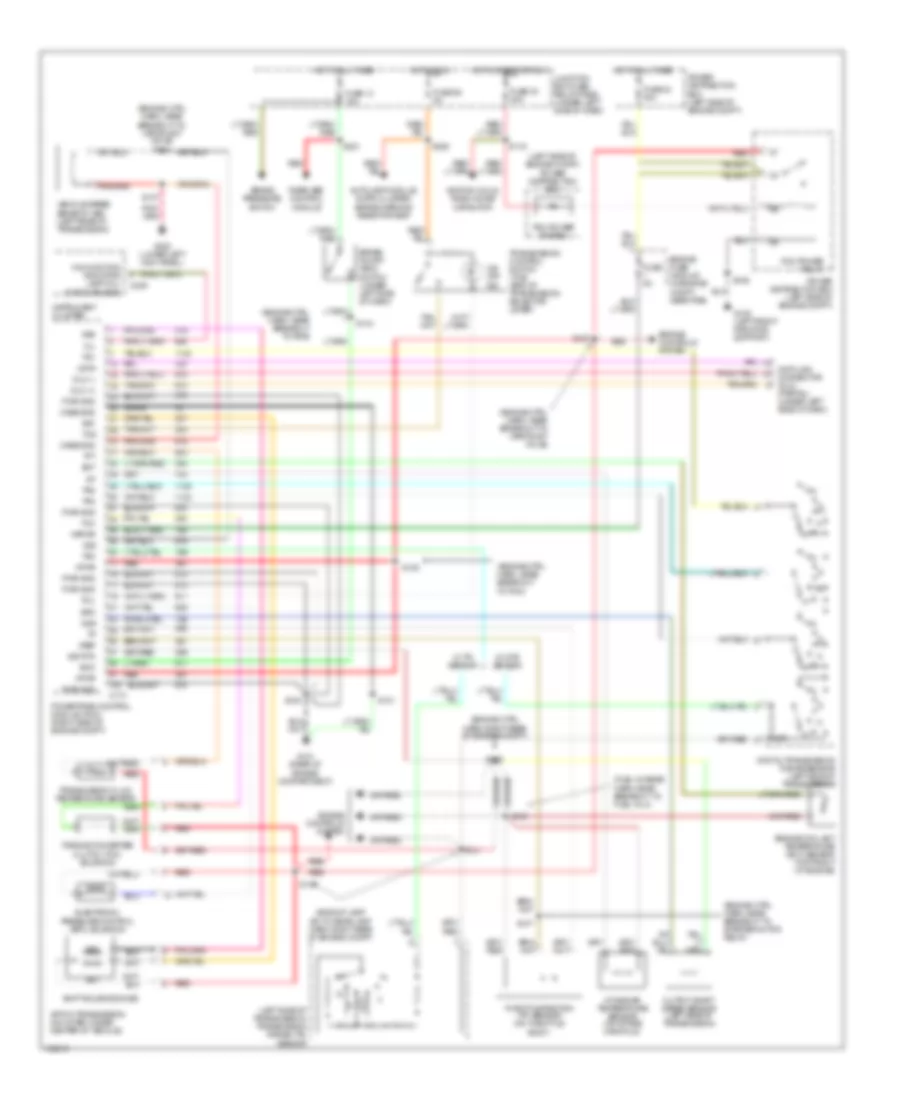 https://portal-diagnostov.com/license.html
Automotive Electricians Portal FZCO
Automotive Electricians Portal FZCO
https://portal-diagnostov.com/license.html
https://portal-diagnostov.com/license.html
Automotive Electricians Portal FZCO
Automotive Electricians Portal FZCOList of elements for 4.6L, Transmission Wiring Diagram, 4R70W for Ford Pickup F150 1997:
- (backup lamp sw to rear lamp harn, right rear of engine compt)
- (bare)
- (engine ctrl harn, near breakout to pcm)
- (engine ctrl harn, near breakout to pdb)
- (engine ctrl harn, near breakout to starter motor relay)
- (engine ctrl harn, near breakout to vapor mgt valve)
- (engine ctrl harn, near breakout to vapor mgt valve) s143
- (engine ctrl harn, right rear of engine compt)
- (fuel charge harn, near breakout to fuel inj 4)
- (left side of engine compt) power distribution box
- (left side of transmission) transmission range (tr) sensor
- 4r70w transmission (mounted under center of vehicle)
- Autolamp module, instr cluster, brake warning resistor assy
- Boo
- Brake on/off (boo) switch (under left side of dash)
- Brake pressure switch
- C174
- C236
- Case gnd
- Data
- Data link connector (dlc) (partial) (under left side of dash)
- Digital transmission range sensor (left side of transmission)
- Dlc (+)
- Dlc (-)
- Ect
- Electronic pressure control (epc) solenoid
- Engine controls system
- Engine coolant temperature (ect) sensor (top front of engine)
- Engine fuse module (in engine compt, near pdb)
- Epc
- Fuse 13 15a
- Fuse 24 30a
- Fuse 29 5a
- Fuse 30 30a
- Fuse 5a
- G108 (left front radiator support)
- G121 (rear of engine compartment)
- G200 (lower left kick panel)
- Hot at all times
- Hot in run
- Hot in start or run
- Iat
- Ignition coils, radio noise capacitor
- Instrument cluster
- Intake air temperature sensor (on intake manifold)
- Junction box fuse/ relay panel (under left side of dash)
- Kapwr
- Malfunction indicator lamp (mil) (check engine)
- Mil
- N d
- O/d off ind
- Oss
- Output shaft speed sensor (left side of transmission)
- Pcm power diode 2
- Pcm power relay
- Power distribution box (left side of engine compt)
- Powertrain control module (pcm) (right side of engine compt)
- Pwr gnd
- R p
- Rear abs control module
- Red
- S100
- S101
- S106
- S107
- S116
- S127
- S128
- S135
- S137
- S138
- S140
- S141
- S144
- S221
- S225
- Shift solenoids (ss)
- Sig rtn
- Ss1
- Ss2
- Tcc
- Tcil
- Tcs
- Tft
- Throttle position (tp) sensor (on throttle body)
- Torque converter clutch (tcc) solenoid
- Tr1
- Tr2
- Tr3
- Tr4
- Transmission control switch (tcs) (end of transmission selector lever)
- Transmission fluid temperature sensor
- Vehicle speed sensor (vss) (left rear of transmission)
- Vpwr
- Vref
- Vss
- W/ dtr sensor
- W/ tr sensor
Transfer Case Wiring Diagram, Electronic for Ford Pickup F150 1997
 https://portal-diagnostov.com/license.html
Automotive Electricians Portal FZCO
Automotive Electricians Portal FZCO
https://portal-diagnostov.com/license.html
https://portal-diagnostov.com/license.html
Automotive Electricians Portal FZCO
Automotive Electricians Portal FZCOList of elements for Transfer Case Wiring Diagram, Electronic for Ford Pickup F150 1997:
- (engine ctrl harn, near breakout to vapor mgt valve) s143
- (lower right kick panel) g203
- (main harn, near breakout to gem)
- (right side of engine compt) 4x2 center axle disconnect solenoid
- (right side of engine compt) 4x4 center axle disconnect solenoid
- (under left side of dash) junction box fuse/ relay panel
- 1.1k ohms
- 3.9k ohms
- 4 wheel drive mode switch
- 4wd low out
- 4wd output
- 4x2 sol
- 4x4 high ind
- 4x4 high range indicator
- 4x4 low ind
- 4x4 low range indicator
- 4x4 mode sw
- 4x4 sol
- Anti-lock brake module
- Apron) g105
- Autolamp mod, tcs switch, brake warning resistor assy
- Bpp sw input
- Brake pedal position switch (under left side of dash)
- Brake pressure switch
- C174
- C236
- C238
- C239
- C241
- C242
- C243
- Digital transmission range (dtr) sensor (all others) (left side of transmission)
- Early 1997 all others
- Flasher relay
- Fuse 13 15a
- Fuse 17 30a
- Fuse 23 10a
- Fuse 29 5a
- G108 (top front radiator support)
- G200 (lower left kick panel)
- Generic electronic module (gem) (behind left side of dash)
- H2l
- H2l rly ctrl
- Hot at all times
- Hot in run or start
- Illumination
- Instrument cluster
- Interior lights (instrument illumination)
- Junction box fuse/ relay panel (under left side of dash)
- L2h
- L2h rly ctrl
- Magnetic clutch
- Neutral sw in
- Not used
- Ohms
- Power distribution box (left side of engine compt)
- Powertrain control module (right side of engine compt)
- Rear abs control module
- Red
- S102
- S120
- S142 (engine ctrl harn, near breakout to pwr dist box)
- S201
- S202
- S213
- S221
- S225
- S228
- S231 (main harn, near breakout to instr cluster)
- S232 (main harn, near breakout to instrument cluster)
- S238
- Shift motor
- Sig return
- Sw a input
- Sw b input
- Sw c input
- Sw d input
- Tcec rly ctrl
- Trailer tow battery relay
- Transfer case assembly (below vehicle, behind transmission)
- Transfer case electric clutch relay (in rpo relay block)
- Transfer case shift relay module (behind center of dash)
- Transmission range (tr) sensor (early 1997) (left side of transmission)
- Vehicle speed sensor (vss) (left rear of transmission)
- Vss (+)
- Vss (-)
- Wiper/washer (multi-function switch)
Transfer Case Wiring Diagram, Mechanical for Ford Pickup F150 1997
 https://portal-diagnostov.com/license.html
Automotive Electricians Portal FZCO
Automotive Electricians Portal FZCO
https://portal-diagnostov.com/license.html
https://portal-diagnostov.com/license.html
Automotive Electricians Portal FZCO
Automotive Electricians Portal FZCOList of elements for Transfer Case Wiring Diagram, Mechanical for Ford Pickup F150 1997:
- (behind left side of dash) generic electronic module (gem)
- (engine ctrl harn, near breakout to pwr dist box)
- (right side of engine compt) 4x2 center axle disconnect solenoid
- (right side of engine compt) 4x4 center axle disconnect solenoid
- 4wd low out
- 4x2
- 4x2 sol
- 4x4 high ind
- 4x4 high range indicator
- 4x4 low ind
- 4x4 low indicator switch (left side of transmission)
- 4x4 low range indicator
- 4x4 sol
- 4x4 sw in
- Anti-lock brake module
- Autolamp mod, tcs switch, brake warning resistor assy
- C174
- C236
- C238
- C239
- C241
- Flasher relay
- Fuse 17 30a
- Fuse 23 10a
- Fuse 29 5a
- Hot at all times
- Hot in run or start
- Instrument cluster
- Junction box fuse/ relay panel (under left side of dash)
- Magnetic clutch
- Power distribution box (left side of engine compt)
- Powertrain control module (right side of engine compt)
- Red
- S120
- S142
- S225
- S228
- S232 (main harn, near breakout to instrument cluster)
- Sotf rly ctrl
- Trailer tow battery relay
- Transfer case assembly
- Transfer case electric clutch relay (in rpo relay block)
5.4L
5.4L, Transmission Wiring Diagram, E4OD for Ford Pickup F150 1997
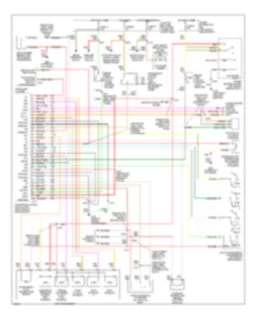 https://portal-diagnostov.com/license.html
Automotive Electricians Portal FZCO
Automotive Electricians Portal FZCO
https://portal-diagnostov.com/license.html
https://portal-diagnostov.com/license.html
Automotive Electricians Portal FZCO
Automotive Electricians Portal FZCOList of elements for 5.4L, Transmission Wiring Diagram, E4OD for Ford Pickup F150 1997:
- (backup lamp sw to rear lamp harn, right rear of eng compt)
- (bare)
- (engine ctrl harn, left rear of engine compt) ngv only
- (engine ctrl harn, near breakout to starter motor relay)
- (engine ctrl harn, near breakout to vapor mgt valve)
- (engine ctrl harn, near breakout to vapor mgt valve) s143
- (engine ctrl harn, right rear of engine compt)
- (fuel charge harn, near breakout to fuel inj 4)
- (left side of engine compt) power distribution box
- (under center of dash) (partial)
- Autolamp module, instr cluster, brake warning resistor assy
- Boo
- Brake pedal position switch (under left side of dash)
- Brake pressure switch
- Breakout to pdb)
- C174
- C237
- Case gnd
- Ccs
- Coast clutch solenoid
- Data
- Data link connector (dlc)
- Digital transmission range sensor (left side of transmission)
- Dlc (+)
- Dlc (-)
- E4od transmission
- Ect
- Electronic pressure control (epc) solenoid
- Eng coolant temp gauge
- Engine controls system
- Engine coolant temperature (ect) sensor (top front of engine)
- Engine fuse module (in engine compt, near pdb)
- Epc
- Fuse 13 15a
- Fuse 24 30a
- Fuse 29 5a
- Fuse 30 30a
- Fuse 5a
- G108 (left front radiator support)
- G123 (rear of engine compartment)
- G200 (lower left kick panel)
- Hot at all times
- Hot in run
- Hot in start or run
- Iat
- Ignition coils, radio noise capacitor
- Instrument cluster
- Intake air temperature sensor (on intake manifold)
- Junction box fuse/ relay panel (under left side of dash)
- Kapwr
- Malfunction indicator lamp (mil) (check engine)
- Mil
- Ngv module (on front of engine)
- O/d off ind
- Pcm power diode
- Pcm power relay
- Power distribution box (left side of engine compt)
- Powertrain control module (pcm) (right side of engine compt)
- Pwr gnd
- R p
- Rear abs control module
- Red
- S100
- S101
- S106
- S107
- S116
- S123
- S127
- S128 (engine ctrl harn, near breakout to pcm)
- S135
- S137
- S138
- S140
- S141
- S156
- S157
- S158
- S207
- S221
- S225
- Shift solenoid
- Sig rtn
- Ss1
- Ss2
- Tcc
- Tcil
- Tcs
- Tft
- Throttle position (tp) sensor (on throttle body)
- Torque converter clutch (tcc) solenoid
- Tr1
- Tr2
- Tr3
- Tr4
- Transmission control switch (tcs) (end of transmission selector lever)
- Transmission fluid temperature sensor
- Vehicle speed sensor (vss) (left rear of transmission)
- Vpwr
- Vref
- Vss
Transfer Case Wiring Diagram, Electronic for Ford Pickup F150 1997
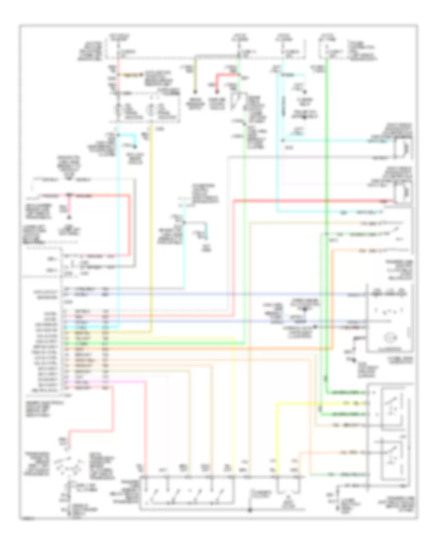 https://portal-diagnostov.com/license.html
Automotive Electricians Portal FZCO
Automotive Electricians Portal FZCO
https://portal-diagnostov.com/license.html
https://portal-diagnostov.com/license.html
Automotive Electricians Portal FZCO
Automotive Electricians Portal FZCOList of elements for Transfer Case Wiring Diagram, Electronic for Ford Pickup F150 1997:
- (engine ctrl harn, near breakout to vapor mgt valve) s143
- (lower right kick panel) g203
- (main harn, near breakout to gem)
- (right side of engine compt) 4x2 center axle disconnect solenoid
- (right side of engine compt) 4x4 center axle disconnect solenoid
- (under left side of dash) junction box fuse/ relay panel
- 1.1k ohms
- 3.9k ohms
- 4 wheel drive mode switch
- 4wd low out
- 4wd output
- 4x2 sol
- 4x4 high ind
- 4x4 high range indicator
- 4x4 low ind
- 4x4 low range indicator
- 4x4 mode sw
- 4x4 sol
- Anti-lock brake module
- Apron) g105
- Autolamp mod, tcs switch, brake warning resistor assy
- Bpp sw input
- Brake pedal position switch (under left side of dash)
- Brake pressure switch
- C174
- C236
- C238
- C239
- C241
- C242
- C243
- Digital transmission range (dtr) sensor (all others) (left side of transmission)
- Early 1997 all others
- Flasher relay
- Fuse 13 15a
- Fuse 17 30a
- Fuse 23 10a
- Fuse 29 5a
- G108 (top front radiator support)
- G200 (lower left kick panel)
- Generic electronic module (gem) (behind left side of dash)
- H2l
- H2l rly ctrl
- Hot at all times
- Hot in run or start
- Illumination
- Instrument cluster
- Interior lights (instrument illumination)
- Junction box fuse/ relay panel (under left side of dash)
- L2h
- L2h rly ctrl
- Magnetic clutch
- Neutral sw in
- Not used
- Ohms
- Power distribution box (left side of engine compt)
- Powertrain control module (right side of engine compt)
- Rear abs control module
- Red
- S102
- S120
- S142 (engine ctrl harn, near breakout to pwr dist box)
- S201
- S202
- S213
- S221
- S225
- S228
- S231 (main harn, near breakout to instr cluster)
- S232 (main harn, near breakout to instrument cluster)
- S238
- Shift motor
- Sig return
- Sw a input
- Sw b input
- Sw c input
- Sw d input
- Tcec rly ctrl
- Trailer tow battery relay
- Transfer case assembly (below vehicle, behind transmission)
- Transfer case electric clutch relay (in rpo relay block)
- Transfer case shift relay module (behind center of dash)
- Transmission range (tr) sensor (early 1997) (left side of transmission)
- Vehicle speed sensor (vss) (left rear of transmission)
- Vss (+)
- Vss (-)
- Wiper/washer (multi-function switch)
Transfer Case Wiring Diagram, Mechanical for Ford Pickup F150 1997
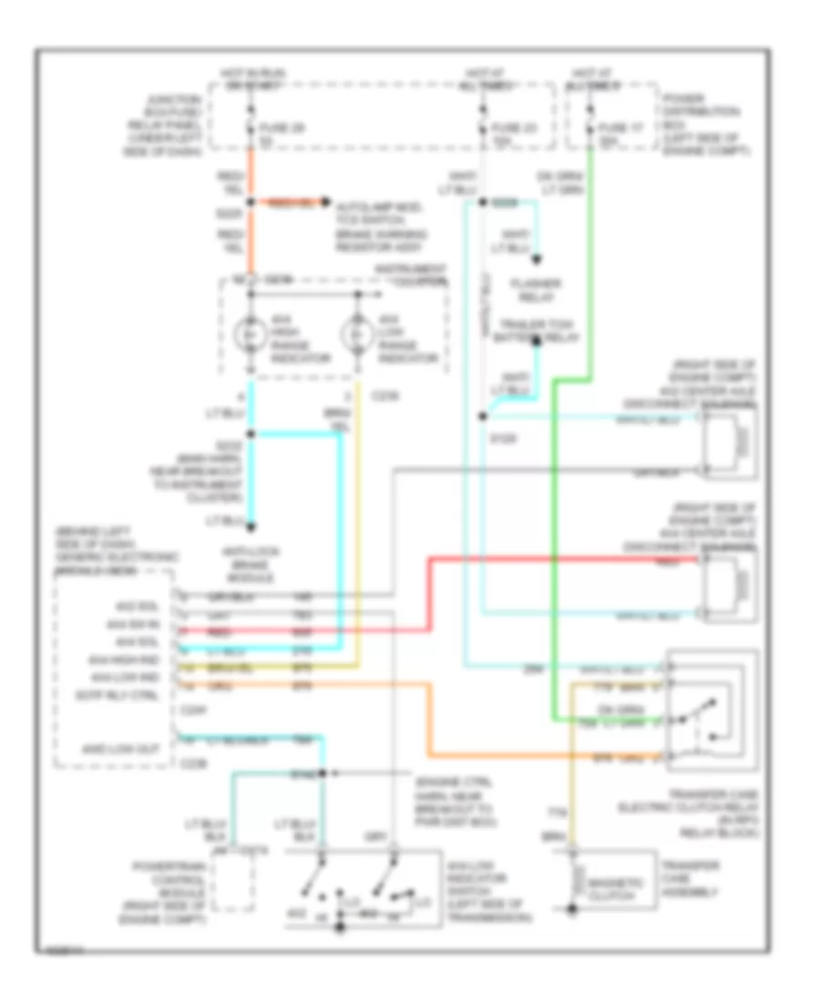 https://portal-diagnostov.com/license.html
Automotive Electricians Portal FZCO
Automotive Electricians Portal FZCO
https://portal-diagnostov.com/license.html
https://portal-diagnostov.com/license.html
Automotive Electricians Portal FZCO
Automotive Electricians Portal FZCOList of elements for Transfer Case Wiring Diagram, Mechanical for Ford Pickup F150 1997:
- (behind left side of dash) generic electronic module (gem)
- (engine ctrl harn, near breakout to pwr dist box)
- (right side of engine compt) 4x2 center axle disconnect solenoid
- (right side of engine compt) 4x4 center axle disconnect solenoid
- 4wd low out
- 4x2
- 4x2 sol
- 4x4 high ind
- 4x4 high range indicator
- 4x4 low ind
- 4x4 low indicator switch (left side of transmission)
- 4x4 low range indicator
- 4x4 sol
- 4x4 sw in
- Anti-lock brake module
- Autolamp mod, tcs switch, brake warning resistor assy
- C174
- C236
- C238
- C239
- C241
- Flasher relay
- Fuse 17 30a
- Fuse 23 10a
- Fuse 29 5a
- Hot at all times
- Hot in run or start
- Instrument cluster
- Junction box fuse/ relay panel (under left side of dash)
- Magnetic clutch
- Power distribution box (left side of engine compt)
- Powertrain control module (right side of engine compt)
- Red
- S120
- S142
- S225
- S228
- S232 (main harn, near breakout to instrument cluster)
- Sotf rly ctrl
- Trailer tow battery relay
- Transfer case assembly
- Transfer case electric clutch relay (in rpo relay block)
WARNING SYSTEMS
Warning System Wiring Diagrams for Ford Pickup F150 1997
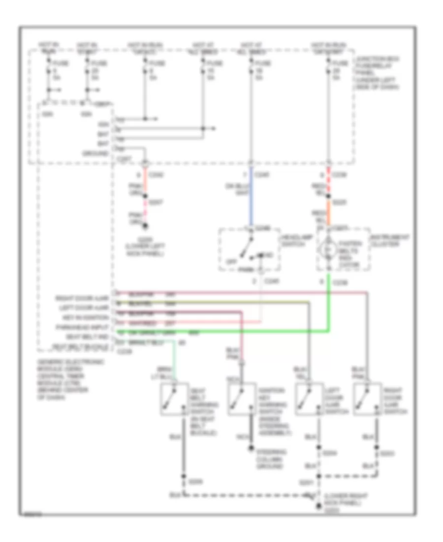 https://portal-diagnostov.com/license.html
Automotive Electricians Portal FZCO
Automotive Electricians Portal FZCO
https://portal-diagnostov.com/license.html
https://portal-diagnostov.com/license.html
Automotive Electricians Portal FZCO
Automotive Electricians Portal FZCOList of elements for Warning System Wiring Diagrams for Ford Pickup F150 1997:
- (lower right kick panel) g203
- Bat
- C237
- C238
- C239
- C242
- C245
- C267
- Fasten belts indi- cator
- Fuse 5a
- G200 (lower left kick panel)
- Generic electronic module (gem)/ central timer module (ctm) (behind center of dash)
- Ground
- Head
- Headlamp switch
- Hot at all times
- Hot in run
- Hot in run or acc
- Hot in run or start
- Hot in start
- Ign
- Ignition key warning switch (inside steering assembly)
- Instrument cluster
- Junction box fuse/relay panel (under left side of dash)
- Key in ignition
- Left door ajar
- Left door ajar switch
- Nca
- Off
- Park
- Park/head input
- Right door ajar
- Right door ajar switch
- S201
- S203
- S204
- S206
- S207
- S225
- Seat belt buckle
- Seat belt ind
- Seat belt warning switch (in seat belt buckle)
- Steering column ground
WIPER/WASHER
Wiper/Washer Wiring Diagram for Ford Pickup F150 1997
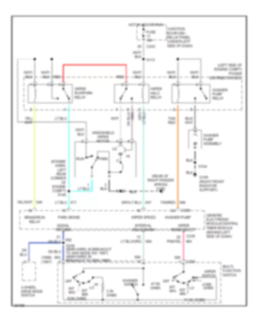 https://portal-diagnostov.com/license.html
Automotive Electricians Portal FZCO
Automotive Electricians Portal FZCO
https://portal-diagnostov.com/license.html
https://portal-diagnostov.com/license.html
Automotive Electricians Portal FZCO
Automotive Electricians Portal FZCOList of elements for Wiper/Washer Wiring Diagram for Ford Pickup F150 1997:
- (1998) (1997)
- (engine harn, left rear corner of engine compt) s146
- (left side of engine compt) power distribution box
- (rear of right fender apron) g105
- 103k ohms
- 11.3k
- 3.3k ohms
- 4 wheel drive mode switch
- 4.08k
- Brake/run relay
- C239
- C243
- C259
- Fuse 30a
- G109 (right front radiator support)
- Generic electronic module/central timer module (behind left side of dash)
- Hot in acc or run
- Int max
- Int min
- Interval delay/wash
- Junction box/fuse/ relay panel (under left side of dash)
- Multi- function switch
- Off
- Off 47.6k ohms
- Ohms
- Park
- Park sense
- Red
- Run
- S102
- S104
- S113
- S238 (main harn, in breakout to 4wd mode sw; 1997) (main harn, in breakout to gem; 1998)
- Signal return
- Tan/ red
- Tan/red
- Washer pump
- Washer pump assembly
- Washer pump relay
- Washer switch
- Windshield wiper motor
- Wiper hi/lo relay
- Wiper mode select
- Wiper run/park relay
- Wiper speed
- Wiper switch

 Čeština
 Dansk
Dansk Deutsch
 Ελληνικά
 English
 English
 Español
 Suomi
Suomi Français
 Français
 עברית
עברית Hrvatski
 Magyar
 Italiano
 日本語
日本語 한국어
한국어 Nederlands
 Polski
 Português
 Português
 Română
 Русский
 Slovenčina
 Slovenščina
 Svenska
 Türkçe
