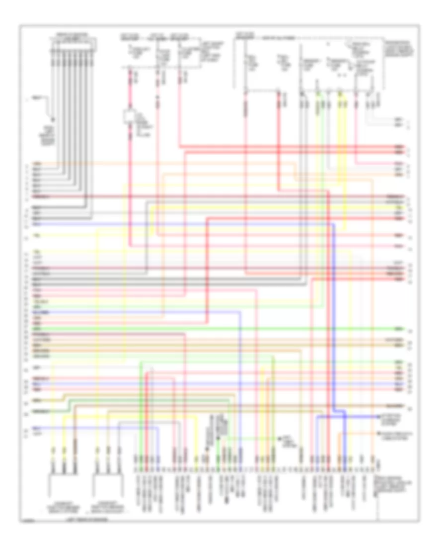
AIR CONDITIONING
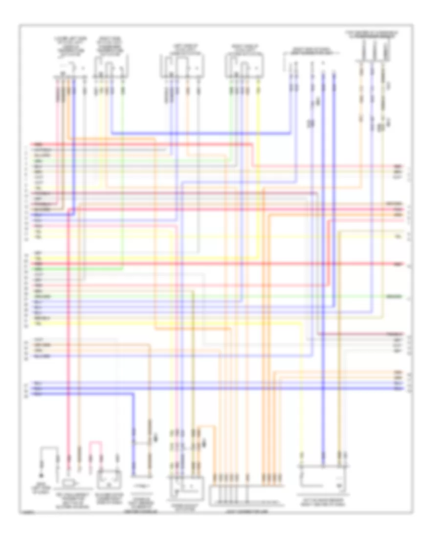
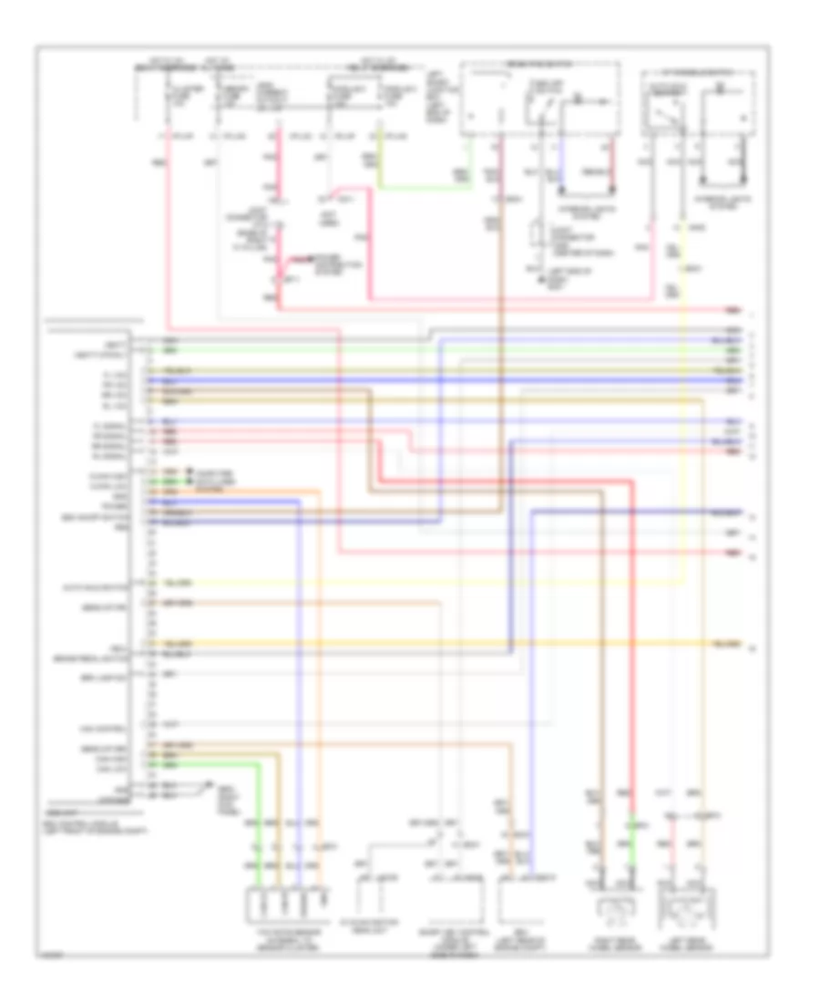
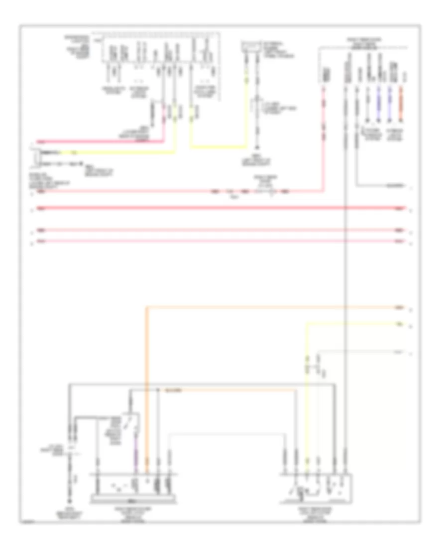
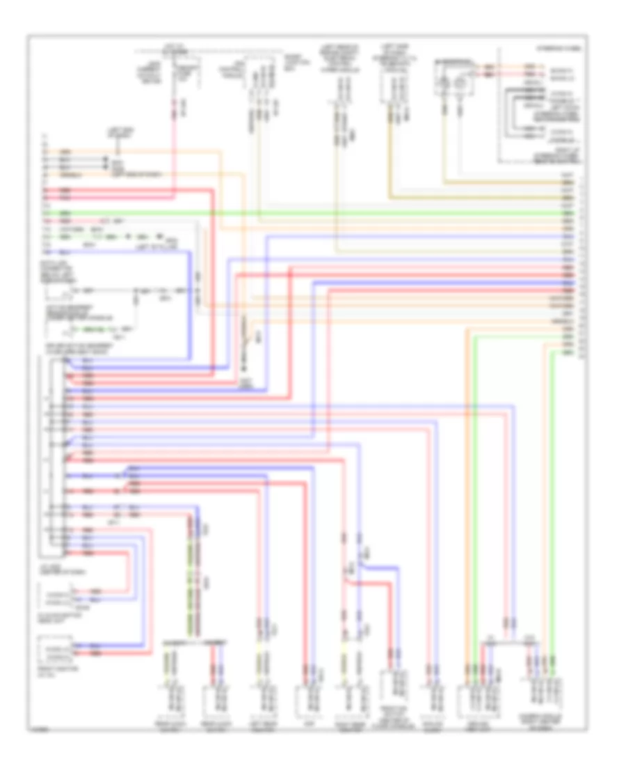
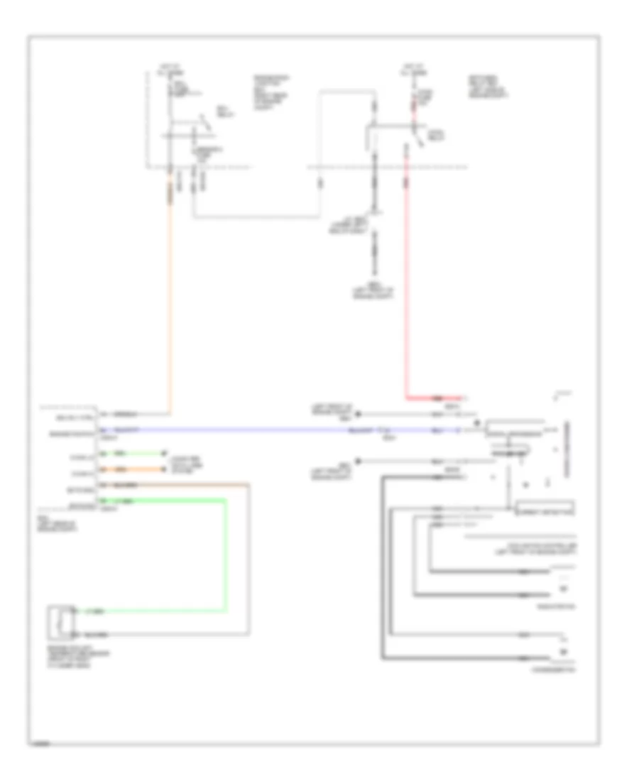
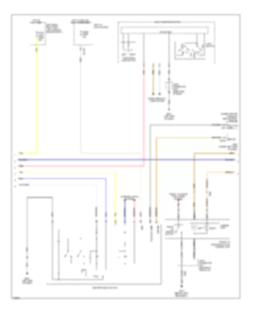
Automatic A/C Wiring Diagram (1 of 4) for Hyundai Equus Ultimate 2014
 https://portal-diagnostov.com/license.html
Automotive Electricians Portal FZCO
Automotive Electricians Portal FZCO
https://portal-diagnostov.com/license.html
https://portal-diagnostov.com/license.html
Automotive Electricians Portal FZCO
Automotive Electricians Portal FZCO
List of elements for Automatic A/C Wiring Diagram (1 of 4) for Hyundai Equus Ultimate 2014:
- (left front of engine compt) ge03
- (left side of dash) gm02
- (under left end of dash) joint connector je02
- A/c control module (center of dash)
- A/con fuse 10a
- Active incar sens (+)
- Ambient sens (+)
- Ambient sensor (behind center of front bumper)
- Aqs sens (+)
- Aqs sensor (behind center of front bumper)
- Blower fuse 40a
- Blower relay
- Console duct actr f/b
- Console duct actr floor
- Console duct actr vent sw
- Console duct sens (+)
- Console temp actr 'a' cool
- Console temp actr 'a' f/b
- Console temp actr 'a' warm
- Console temp actr cool
- Console temp actr f/b
- Console temp actr warm
- Console temperature actuator "a" (left side of hvac unit)
- Def actr open
- Defog actr close
- Defog actr f/b
- Diagnosis
- Drv temp actr cool
- Drv temp actr f/b
- Drv temp actr warm
- E/r junction box (right rear of engine compt)
- E/r-e1b
- E/r-e2b
- Ee21
- Em21
- Em41
- Evap sens (+)
- Evaporator sensor (right side of dash, on hvac assembly)
- Ge04 (lower right rear of engine compt)
- Ground
- Hot at all times
- Humidity sens
- Intake actr f/b
- Intake actr fre
- Intake actr rec
- Joint connector uma
- M07-a
- Mode actr def
- Mode actr f/b
- Mode actr vent
- Pass temp actr cool
- Pass temp actr f/b
- Pass temp actr warm
- Pnk
- Red
- Sens gnd
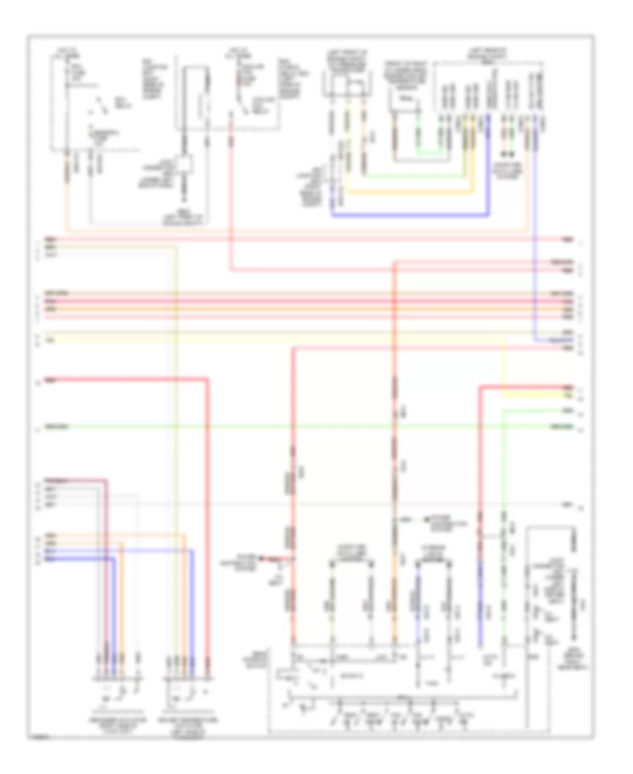
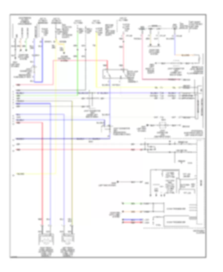
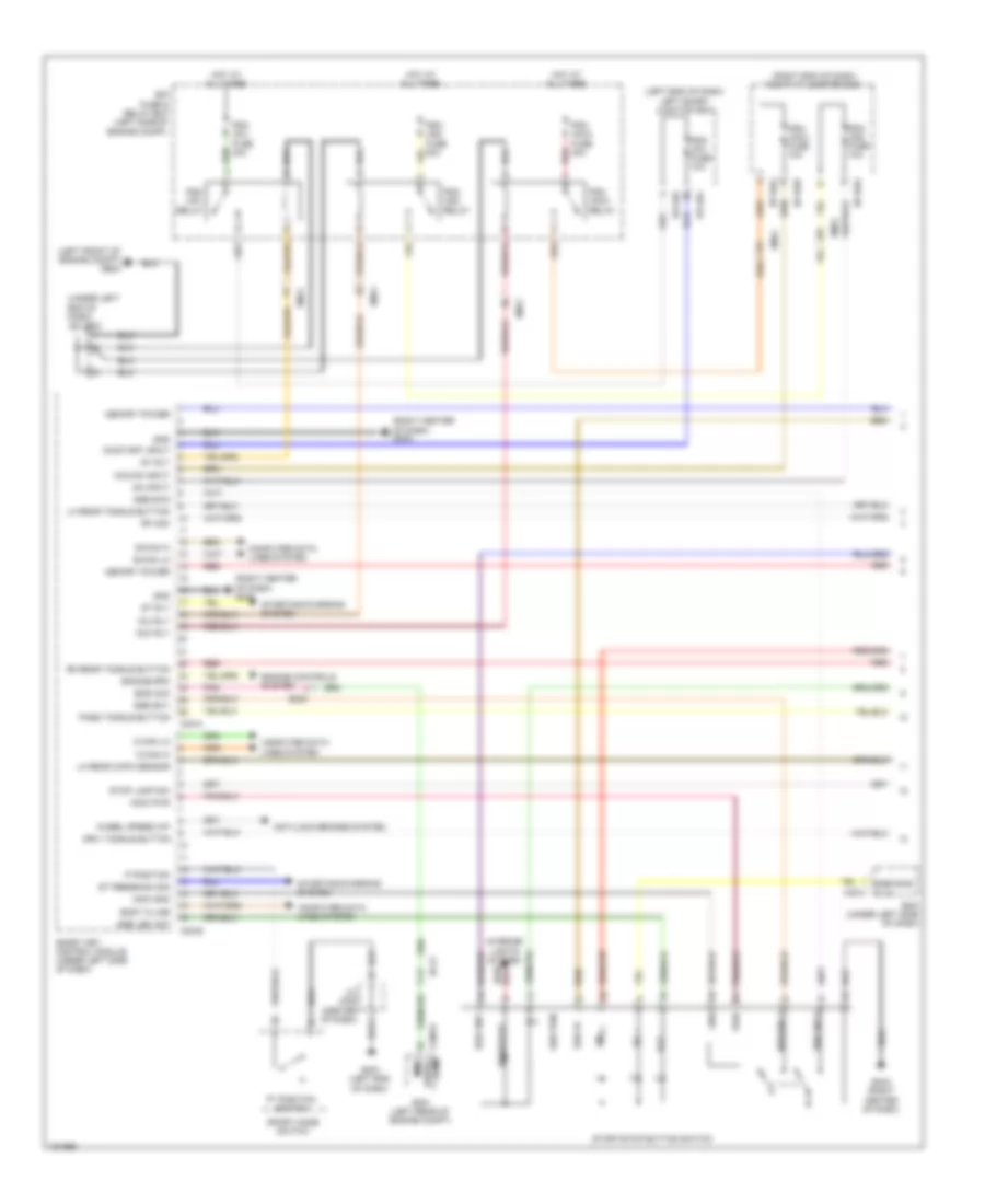
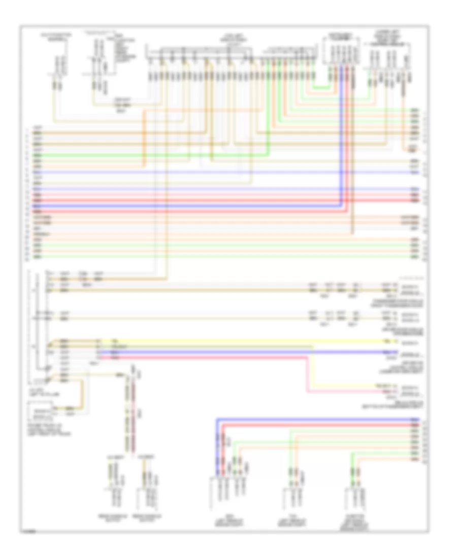
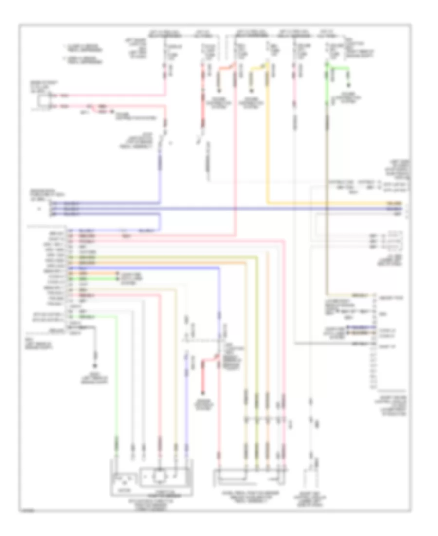
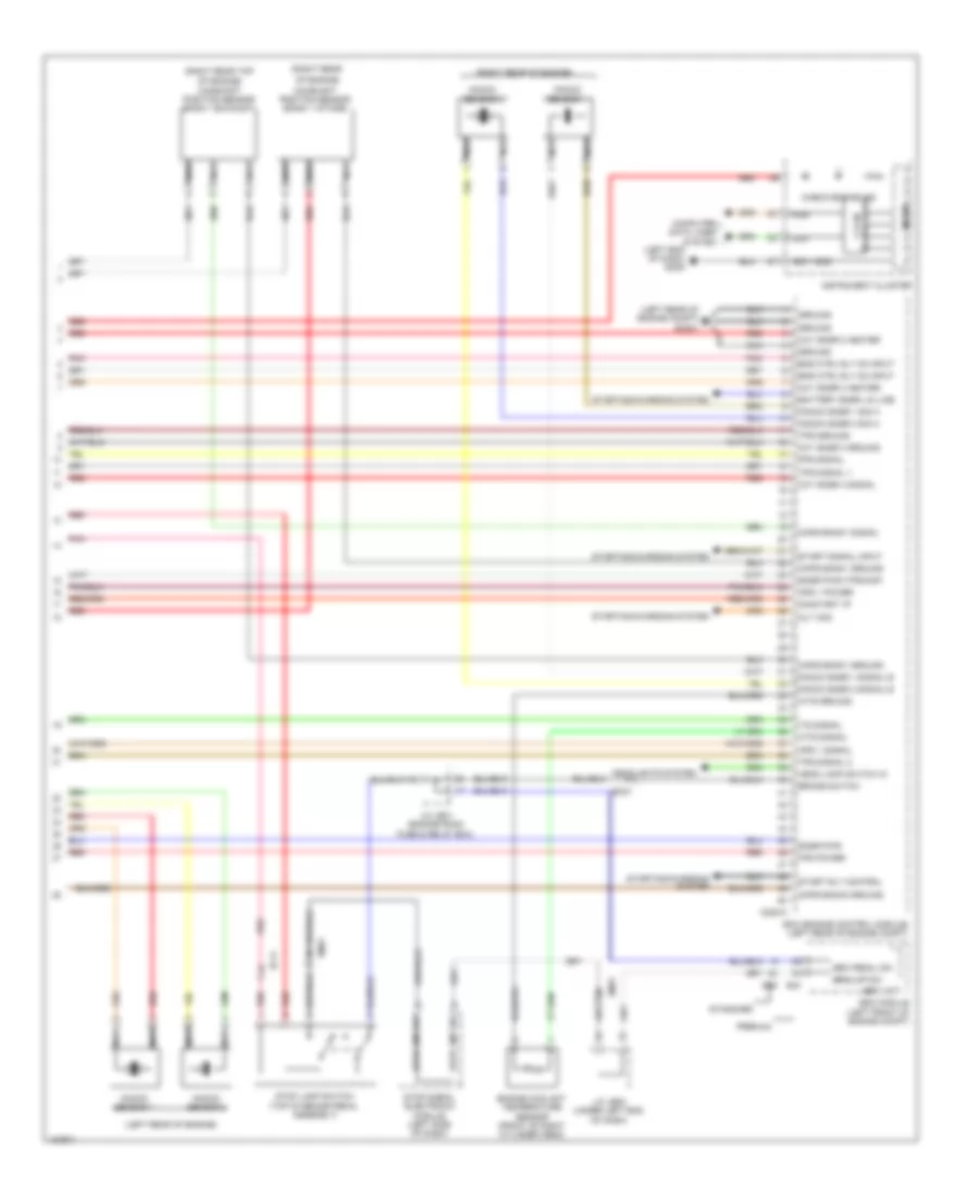
Automatic A/C Wiring Diagram (2 of 4) for Hyundai Equus Ultimate 2014
 https://portal-diagnostov.com/license.html
Automotive Electricians Portal FZCO
Automotive Electricians Portal FZCO
https://portal-diagnostov.com/license.html
https://portal-diagnostov.com/license.html
Automotive Electricians Portal FZCO
Automotive Electricians Portal FZCOList of elements for Automatic A/C Wiring Diagram (2 of 4) for Hyundai Equus Ultimate 2014:
- (left side of hvac unit) mode actuator
- (lower left side of hvac unit) console temperature actuator
- (right end of dash) joint connector jm07
- (right side of hvac unit) intake actuator
- (right side of hvac unit) passenger temperature actuator
- (top center of windshield) auto defogger sensor
- Active incar sensor (right center of dash)
- Blower motor (under right side of dash)
- Console duct actuator
- Console duct sensor (in rear of center console)
- Em41
- Fet (field effect transistor) (bottom of blower housing)
- Fr21
- Gm02 (left side of dash)
- Humidity
- Joint connector umb
- Mf21
- Mm11
- Pnk
- Red
- Sensor (+)
- Sensor (-)
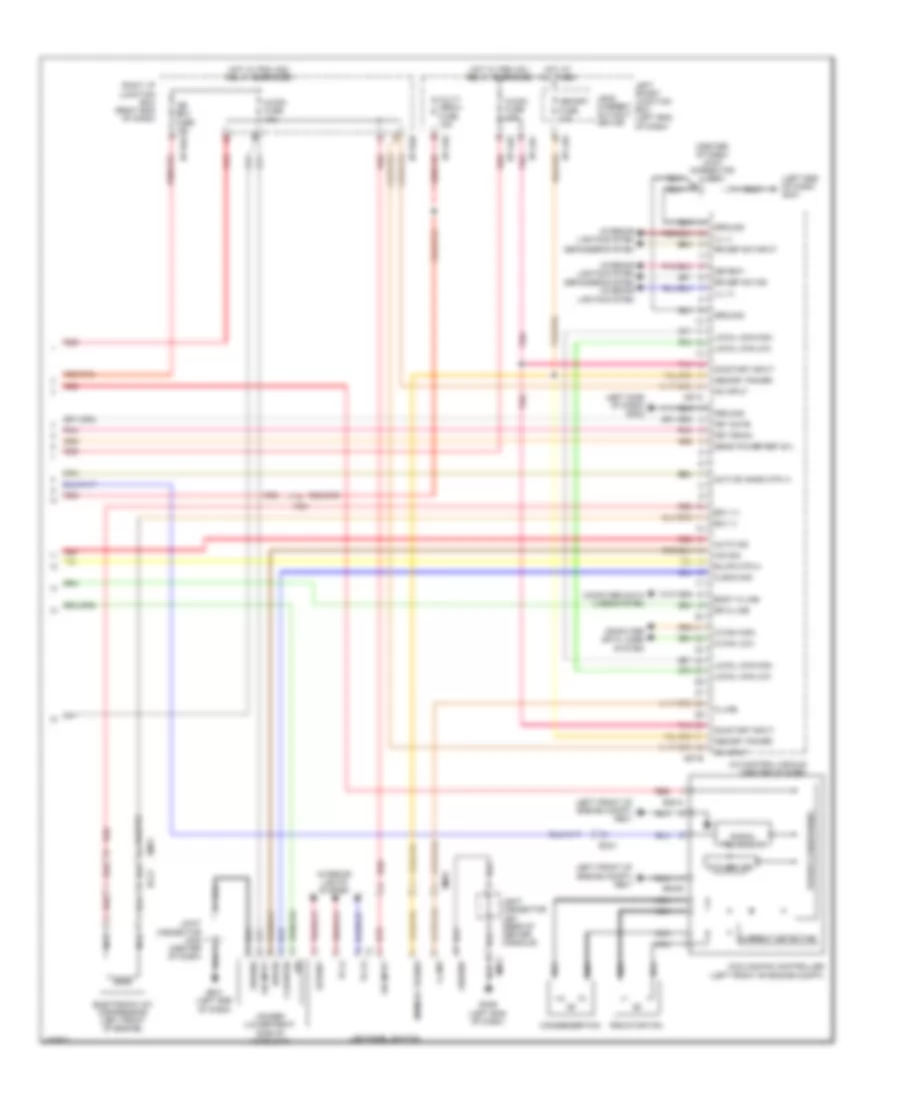
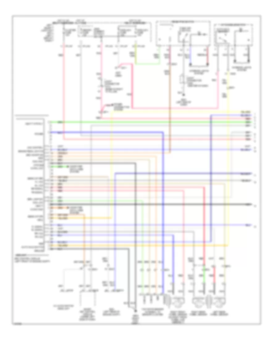
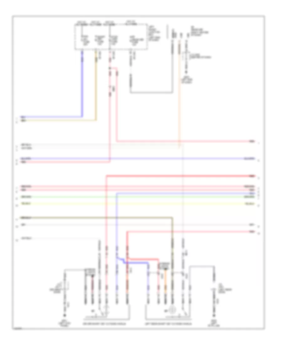
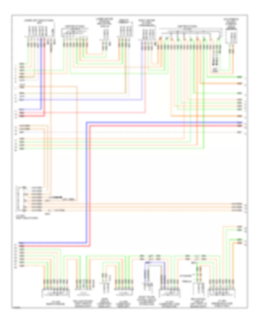
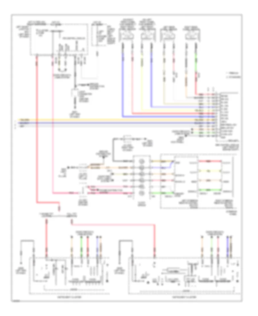
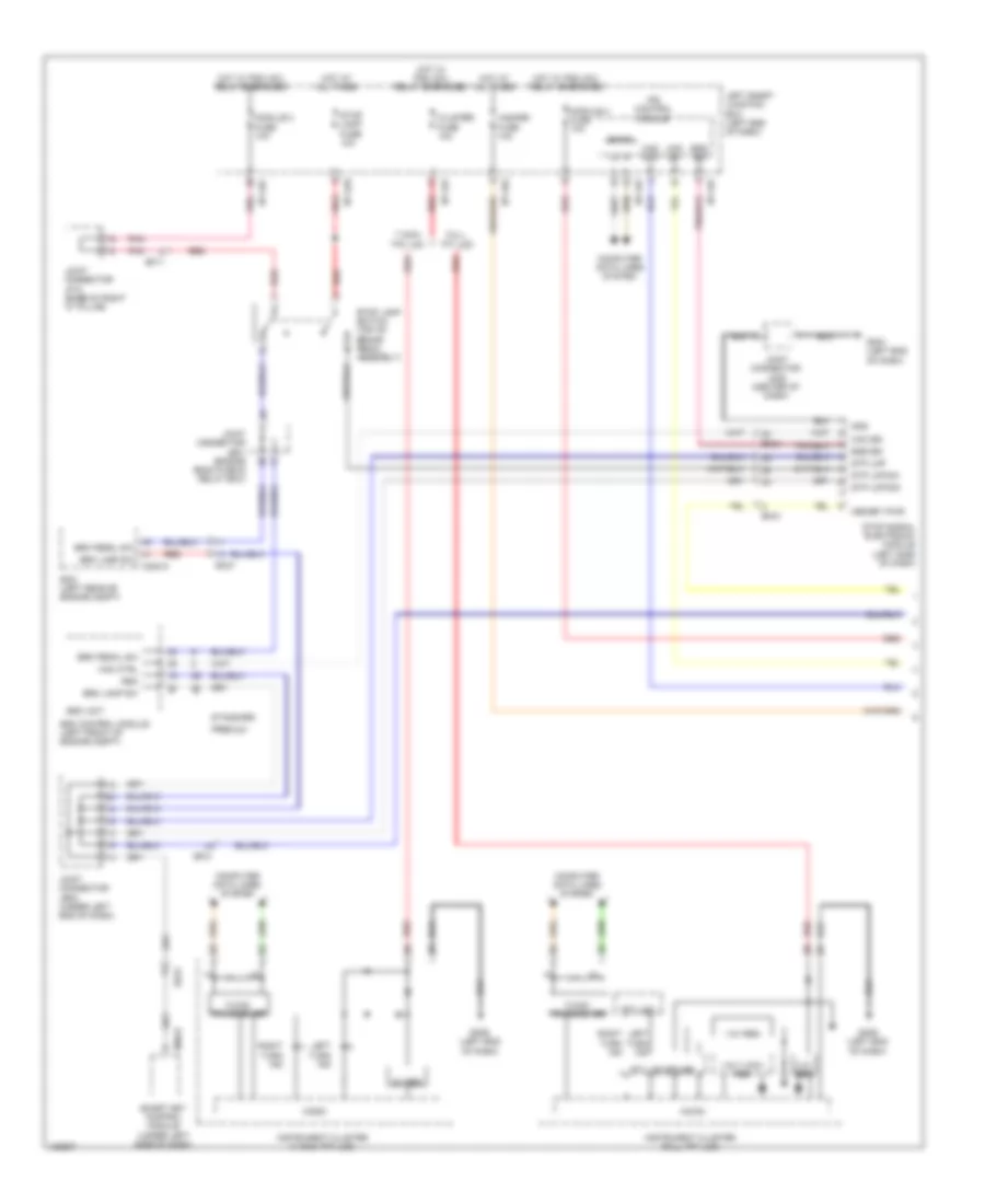
Automatic A/C Wiring Diagram (3 of 4) for Hyundai Equus Ultimate 2014
 https://portal-diagnostov.com/license.html
Automotive Electricians Portal FZCO
Automotive Electricians Portal FZCO
https://portal-diagnostov.com/license.html
https://portal-diagnostov.com/license.html
Automotive Electricians Portal FZCO
Automotive Electricians Portal FZCOList of elements for Automatic A/C Wiring Diagram (3 of 4) for Hyundai Equus Ultimate 2014:
- (aps/apt/ftps) sens sply
- (front of right cylinder head) engine coolant temperature sensor
- (left front of engine compt) a/c pressure transducer
- (left rear of engine compt) ecm
- 12v
- 5:5 seat
- 6:4 seat
- Auto ind
- Auto/ off
- B-can ic
- C-can high
- C-can low
- C200-a
- C200-k
- Computer data lines system
- Cooling fan fuse 70a
- Cooling fan relay
- Cpu
- Defogger actuator (right side of hvac unit)
- Driver temperature actuator (left side of hvac unit)
- E/r fuse & relay box (left side of engine compt)
- E/r junction box (right rear of engine compt)
- E/r-cta
- E/r-e2a
- Ec21
- Ecu fuse 30a
- Ecu relay
- Ecu rly ctrl
- Eng fan pwm
- Fan down
- Fan up
- Fs41
- Ge03 (left front of engine compt)
- Gf08 (behind right rear seat)
- Gnd
- High
- Hot at all times
- Ig2
- Ill (+)
- Ill (-)
- Interior lights system
- Joint connector je02 (under left end of dash)
- Joint connector js31 (under left side of driver seat)
- K-line ic
- Low
- Mf21
- Mode
- Pnk
- Power distribution system
- Rear console switch
- Red
- S27-a
- S27-b
- S37-a
- S37-b
- Sens gnd
- Sens sig
- Sensor 2 fuse 10a
- Ss31
- Ss41
- Temp down
- Temp up
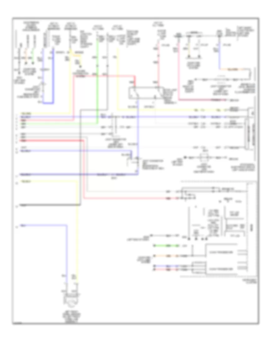
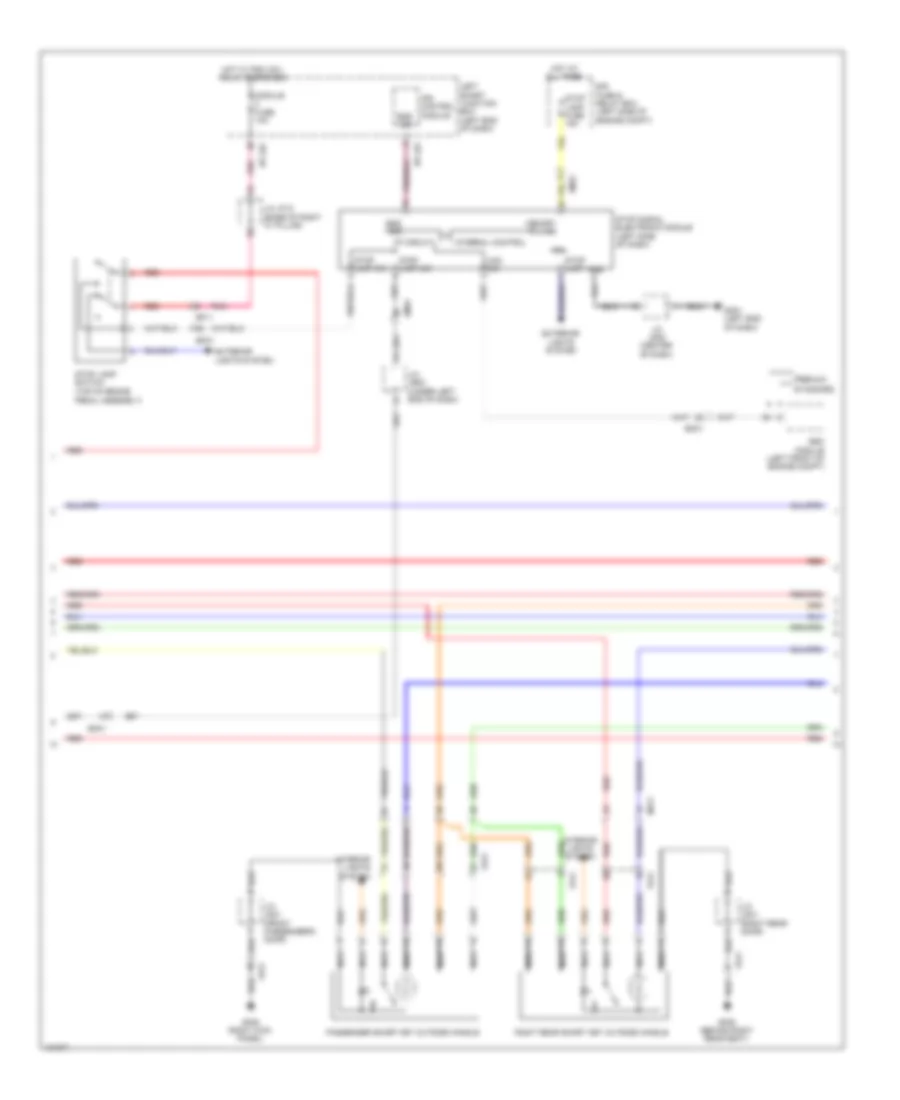
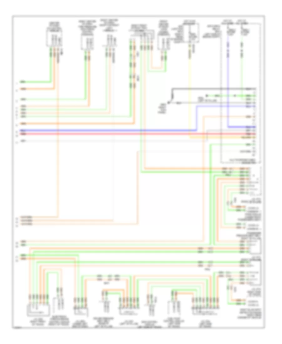
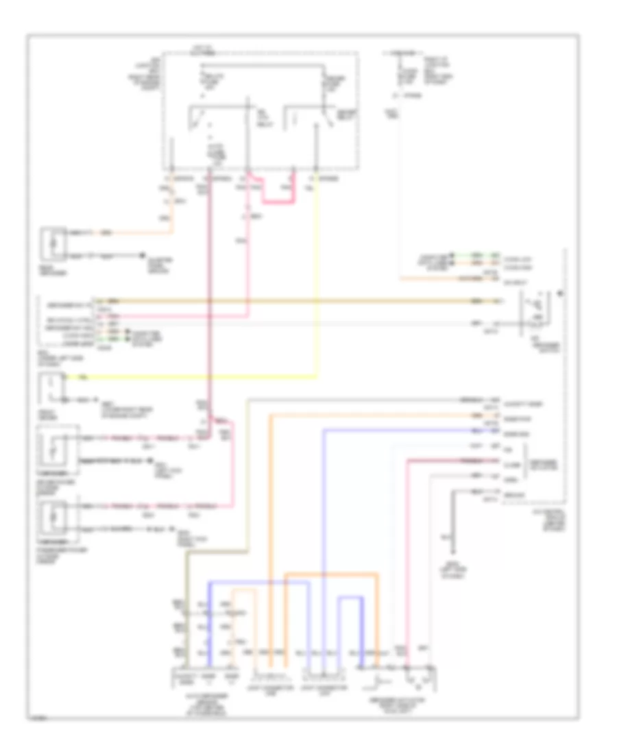
Automatic A/C Wiring Diagram (4 of 4) for Hyundai Equus Ultimate 2014
 https://portal-diagnostov.com/license.html
Automotive Electricians Portal FZCO
Automotive Electricians Portal FZCO
https://portal-diagnostov.com/license.html
https://portal-diagnostov.com/license.html
Automotive Electricians Portal FZCO
Automotive Electricians Portal FZCOList of elements for Automatic A/C Wiring Diagram (4 of 4) for Hyundai Equus Ultimate 2014:
- (center of dash) joint connector jm05
- (left end of dash) gm01
- (left front of engine compt) ge01
- (left side of dash) gm02
- A/c control module (center of dash)
- A/con fuse 10a
- Active incar mtr (+)
- Auto ind
- Blwr mtr (+)
- Body k-line
- C-can high
- C-can low
- C-line
- Clean sig
- Computer data lines system
- Condenser fan
- Cooling fan controller (left front of engine compt)
- Current detecting
- Defogger system
- Defogger system interior lights system
- Detent
- Dia
- E05-a
- E05-b
- Ec21
- Ecv (+)
- Ecv (-)
- Electronic a/c compressor (left front of engine)
- Em21
- Fet drain
- Fet gate
- Fs31
- Gm01 (left end of dash)
- Gm06 (left end of dash)
- Ground
- Hot at all times
- Hot w/ pdm (ig1) relay energized
- Hot w/ pdm (ig2) relay energized
- I/p-lhe
- I/p-lhf
- I/p-lhg
- I/p-rha
- I/p-rhb
- Ice box fuse 15a
- Ill (+)
- Ill (-)
- Interior lights system
- Ion sig
- Ionizer (lower right side of hvac unit)
- Joint connector jm05 (center of dash)
- Joint connector jm21 (rear of center console)
- Lcd panel switch
- Leak current autocut device
- Left smart junction box (left end of dash)
- Local can high
- Local can low
- M07-b
- M07-c
- Memory fuse 10a
- Memory power
- Mm11
- Multi media fuse 15a
- Nca
- On input
- On/start input
- Pnk
- Power conditioning
- Pwn driver
- Radiator fan
- Red
- Right i/p junction box (right end of dash)
- Rr c-line
- Rr def sw ind
- Rr def sw input
- Sens power ref (5v)
- Signal processing
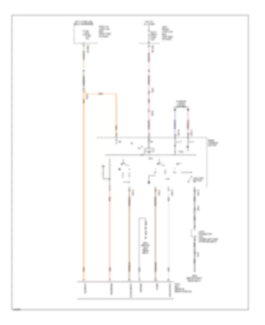
Cool Box Wiring Diagram for Hyundai Equus Ultimate 2014
 https://portal-diagnostov.com/license.html
Automotive Electricians Portal FZCO
Automotive Electricians Portal FZCO
https://portal-diagnostov.com/license.html
https://portal-diagnostov.com/license.html
Automotive Electricians Portal FZCO
Automotive Electricians Portal FZCOList of elements for Cool Box Wiring Diagram for Hyundai Equus Ultimate 2014:
- 12v
- Cool box (rear of rear console)
- Cool box switch
- Cpu
- Diagnosis
- Fs31
- Fs41
- Gf04 (behind left rear seat)
- Gf08 (behind right rear seat)
- Ground
- Hot at all times
- Hot w/ pdm (ig2) relay energized
- I/p-lhg
- I/p-rha
- Ice box fuse 15a
- Ig2
- Ill (+)
- Ill (-)
- Interior lights system
- Joint connector js31 (under left side of driver seat)
- Led output
- Left smart junction box (left end of dash)
- Multi media fuse 15a
- On input
- Pulse input
- Rear console switch
- Red
- Right i/p junction box (right end of dash)
- S-gnd
- S37-a
- S37-b
- Ss31
- Ss41
ANTI-LOCK BRAKES
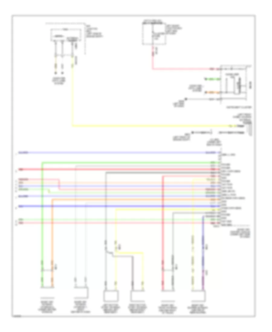
Anti-lock Brakes Wiring Diagram, Premium (1 of 2) for Hyundai Equus Ultimate 2014
 https://portal-diagnostov.com/license.html
Automotive Electricians Portal FZCO
Automotive Electricians Portal FZCO
https://portal-diagnostov.com/license.html
https://portal-diagnostov.com/license.html
Automotive Electricians Portal FZCO
Automotive Electricians Portal FZCOList of elements for Anti-lock Brakes Wiring Diagram, Premium (1 of 2) for Hyundai Equus Ultimate 2014:
- (left end of dash) gm01
- (not used)
- +ecu
- A/t console switch
- A/v & navigation head unit
- Auto hold switch
- Brake pedal switch
- Brk lamp sw
- C-can high
- C-can low
- C200-k
- Can hi
- Can high
- Can lo
- Can low
- Cluster fuse 10a
- Computer data lines system
- Crash pad switch
- Ec21
- Ecm (left rear of engine compt)
- Ef11
- Ef21
- Ef31
- Em31
- Esc control module (left front of engine compt)
- Esc off switch
- Esc on/off switch
- Esc unit
- Fl signal
- Fl vcc
- Fr signal
- Fr vcc
- Ge02 (right kick panel)
- Gnd
- Hac control
- Hot at all times
- Hot w/ ig1 relay energized
- I/p-lhc
- I/p-lhf
- I/p-lhg
- Ill
- Interior lights system
- Joint connector jf12 (base of right "c" pillar)
- Joint connector jm05 (center of dash)
- Leak current autocut device
- Left rear wheel sensor
- Left smart junction box (left end of dash)
- M03-b
- M30-b
- Memory fuse 10a
- Mm02
- Mm11
- Module 2 fuse 10a
- Module 3 fuse 10a
- Mtr gnd
- Nca
- Pnk
- Power
- Power distribution system
- Red
- Right rear wheel sensor
- Rl signal
- Rl vcc
- Rr signal
- Rr vcc
- Rsm
- Sens o/p (fr)
- Sens o/p (rr)
- Smart key control module (under left side of dash)
- Vbatt
- Vbatt mtr rly
- Yaw rate sensor (integral to sensor cluster)
Anti-lock Brakes Wiring Diagram, Premium (2 of 2) for Hyundai Equus Ultimate 2014
 https://portal-diagnostov.com/license.html
Automotive Electricians Portal FZCO
Automotive Electricians Portal FZCO
https://portal-diagnostov.com/license.html
https://portal-diagnostov.com/license.html
Automotive Electricians Portal FZCO
Automotive Electricians Portal FZCOList of elements for Anti-lock Brakes Wiring Diagram, Premium (2 of 2) for Hyundai Equus Ultimate 2014:
- (on steering column) steering angle sensor
- 1.5v/1.275v reg (full tft lcd type) 1.2v reg (7" tft lcd type)
- 1.8v reg (full tft lcd type)
- 3.3v reg
- Abs ind
- Auto hold
- B-can
- B/up lamp fuse 10a
- Brake fluid level sensor (on brake fluid reservoir)
- Brake ind
- Brk fluid sw
- C-can high
- C-can low
- C-can transceiver
- Computer data lines system
- E/r fuse & relay box (left side of engine compt)
- E/r junction block (right rear of engine compt)
- E/r-e1a
- E/r-e2b
- Ec21
- Em31
- Em41
- Esc
- Esc 1 fuse 40a
- Esc 2 fuse 40a
- Esc fuse 10a
- Esc off
- Ess sig
- Ess signal
- Ge03 (left front of engine compt)
- Gm01 (left end of dash)
- Gm06 (left end of dash)
- Gnd
- Ground
- Hac sig
- High
- Hot at all times
- Hot w/ ig1 relay energized
- I/p-lhe
- I/p-lhf
- Input circuit
- Instrument cluster
- Internal control
- Ips
- Ips control module
- Joint connector je01 (engine room fuse & relay box)
- Joint connector je02 (under left end of dash)
- Joint connector jm05 (center of dash)
- Left front wheel sensor (on left front wheel hub assembly)
- Left smart junction box (left end of dash)
- Low
- M-can transceiver
- Memory power
- Micom
- Nca
- On/start i/p
- Power distribution system
- Red
- Right front wheel sensor (on right front wheel hub assembly)
- Stop lamp fuse 10a
- Stop lamp fuse 15a
- Stop lamp switch (top of brake pedal assembly)
- Stop lp
- Stop lp sw
- Stop signal electronic module (left side of dash)
- Stp lp sig
- Tft lcd
- Tft lcd driver
- Vsm off ind
Anti-lock Brakes Wiring Diagram, Standard (1 of 2) for Hyundai Equus Ultimate 2014
 https://portal-diagnostov.com/license.html
Automotive Electricians Portal FZCO
Automotive Electricians Portal FZCO
https://portal-diagnostov.com/license.html
https://portal-diagnostov.com/license.html
Automotive Electricians Portal FZCO
Automotive Electricians Portal FZCOList of elements for Anti-lock Brakes Wiring Diagram, Standard (1 of 2) for Hyundai Equus Ultimate 2014:
- (not used)
- +ecu
- A/t console switch
- A/v & navigation head unit
- Auto hold switch
- Brake pedal switch
- Brk lamp sw
- C-can high
- C-can low
- C200-k
- Can hi
- Can high
- Can lo
- Can low
- Cluster fuse 10a
- Computer data lines system
- Crash pad switch
- Ec21
- Ecm (left rear of engine compt)
- Ef11
- Ef21
- Ef31
- Em31
- Esc control module (left front of engine compt)
- Esc off switch
- Esc on/off sw
- Esc unit
- Fl signal
- Fl vcc
- Fr signal
- Fr vcc
- Ge02 (right kick panel)
- Gm01 (left end of dash)
- Gnd
- Ground
- Hac control
- Hot at all times
- Hot w/ ig1 relay energized
- I/p-lhc
- I/p-lhf
- I/p-lhg
- Ill
- Interior lights system
- Joint connector jf12 (base of right "c" pillar)
- Joint connector jm05 (center of dash)
- Leak current autocut device
- Left rear wheel sensor
- Left smart junction box (left end of dash)
- M03-b
- M30-b
- Memory fuse 10a
- Mm02
- Mm11
- Module 2 fuse 10a
- Module 3 fuse 10a
- Mtr gnd
- Nca
- Pnk
- Power
- Power distribution system
- Red
- Right front wheel sensor (on right front wheel hub assembly)
- Right rear wheel sensor
- Rl signal
- Rl vcc
- Rr signal
- Rr vcc
- Rsm
- Sens o/p (fr)
- Sens o/p (rr)
- Smart key control module (under left side of dash)
- Vbatt
- Vbatt mtr rly
- Yaw rate sensor (integral to sensor cluster)
Anti-lock Brakes Wiring Diagram, Standard (2 of 2) for Hyundai Equus Ultimate 2014
 https://portal-diagnostov.com/license.html
Automotive Electricians Portal FZCO
Automotive Electricians Portal FZCO
https://portal-diagnostov.com/license.html
https://portal-diagnostov.com/license.html
Automotive Electricians Portal FZCO
Automotive Electricians Portal FZCOList of elements for Anti-lock Brakes Wiring Diagram, Standard (2 of 2) for Hyundai Equus Ultimate 2014:
- (on steering column) steering angle sensor
- 1.5v/1.275v reg (full tft lcd type) 1.2v reg (7" tft lcd type)
- 1.8v reg (full tft lcd type)
- 3.3v reg
- Abs ind
- Auto hold
- B-can
- B/up lamp fuse 10a
- Brake fluid level sensor (on brake fluid reservoir)
- Brake ind
- Brk fluid sw
- C-can high
- C-can low
- C-can transceiver
- Computer data lines system
- E/r fuse & relay box (left side of engine compt)
- E/r junction block (right rear of engine compt)
- E/r-e1a
- E/r-e2b
- Ec21
- Em31
- Em41
- Esc
- Esc 1 fuse 40a
- Esc 2 fuse 40a
- Esc fuse 10a
- Esc off
- Ess sig
- Ess signal
- Ge03 (left front of engine compt)
- Gm01 (left end of dash)
- Gm06 (left end of dash)
- Gnd
- Ground
- Hac sig
- High
- Hot at all times
- Hot w/ ig1 relay energized
- I/p-lhe
- I/p-lhf
- Input circuit
- Instrument cluster
- Internal control
- Ips
- Ips control module
- Joint connector je01 (engine room fuse & relay box)
- Joint connector je02 (under left end of dash)
- Joint connector jm05 (center of dash)
- Left front wheel sensor (on left front wheel hub assembly)
- Left smart junction box (left end of dash)
- Low
- M-can transceiver
- Memory power
- Micom
- Nca
- On/start i/p
- Power distribution system
- Red
- Stop lamp fuse 10a
- Stop lamp fuse 15a
- Stop lamp switch (top of brake pedal assembly)
- Stop lp
- Stop lp sw
- Stop signal electronic module (left side of dash)
- Stp lp sig
- Tft lcd
- Tft lcd driver
ANTI-THEFT
Forced Entry Wiring Diagram (1 of 4) for Hyundai Equus Ultimate 2014
 https://portal-diagnostov.com/license.html
Automotive Electricians Portal FZCO
Automotive Electricians Portal FZCO
https://portal-diagnostov.com/license.html
https://portal-diagnostov.com/license.html
Automotive Electricians Portal FZCO
Automotive Electricians Portal FZCOList of elements for Forced Entry Wiring Diagram (1 of 4) for Hyundai Equus Ultimate 2014:
- Ajar switch
- B-can high
- B-can low
- Computer data lines system
- D51-a
- D51-b
- D51-c
- Dd11
- Door key lock
- Door key unlock
- Door lck actuator pwr
- Door lock
- Door lock/unlock
- Door unlock
- Dr lock drv fuse 15a
- Driver door lock actuator (rear of driver door)
- Driver door module (driver's door)
- Driver door pawl switch (rear of driver door)
- Driver power door latch (rear of driver door)
- Ecu
- Fd11
- Gf01 (left kick panel)
- Gf03 (left "c" pillar)
- Ground
- Ground pwr
- Ground sig
- Ground signal
- Hot at all times
- Hot w/ pdm (ig1) relay energized
- I/p-lhc
- I/p-lhe
- Interior lights system
- J/c jd11 (driver's door)
- J/c jf01 (left "c" pillar)
- Key
- Leak current autocut device
- Left smart junction box (left end of dash)
- Lh front door lamp
- Lock
- Memory fuse 10a
- Memory power
- Module fuse 10a
- O/s hdl drv fuse 15a
- On/start input
- Pnk
- Puddle lamp
- Red
- Status inform
- Switch ajar
- Switch pawl
- Unlock
Forced Entry Wiring Diagram (2 of 4) for Hyundai Equus Ultimate 2014
 https://portal-diagnostov.com/license.html
Automotive Electricians Portal FZCO
Automotive Electricians Portal FZCO
https://portal-diagnostov.com/license.html
https://portal-diagnostov.com/license.html
Automotive Electricians Portal FZCO
Automotive Electricians Portal FZCOList of elements for Forced Entry Wiring Diagram (2 of 4) for Hyundai Equus Ultimate 2014:
- (right rear door) j/c jd41
- (right rear door) right rear door module
- B-can
- B/a horn
- Burglar alarm horn (lower left rear of engine compt)
- Communication lin
- Communication local
- Computer data lines system
- Dd41
- Dr lk
- Dr unlk
- E/r-e1a
- E/r-e1b
- Ecu
- Engine room junction box (right rear of engine compt)
- Ext buzzer
- Exterior lights system
- External buzzer (left front wheel housing)
- Fam
- Fam-a
- Fam-b
- Fam-c
- Fd41
- Ge03 (left front of engine compt)
- Ge04 (lower right rear of engine compt)
- Gf09 (behind right rear seat)
- Ground
- Ground signal
- Headlights system
- High
- Ill (+)
- Interior lights system
- J/c jd41 (right rear door)
- J/c je02 (under left end of dash)
- Lh head lamp hi
- Lh tail lp
- Low
- Nca
- On/start input
- P-gnd
- Pnk
- Power memory
- Power windows system
- Rear door mood lamp
- Red
- Rh head lamp hi
- Rh tail lp
- Right rear door lock actuator (rear of right door)
- Right rear door pawl switch (rear of right door)
- Right rear power door latch (rear of right door)
- Switch ajar
- Switch pawl
- Unlock status door lock/
Forced Entry Wiring Diagram (3 of 4) for Hyundai Equus Ultimate 2014
 https://portal-diagnostov.com/license.html
Automotive Electricians Portal FZCO
Automotive Electricians Portal FZCO
https://portal-diagnostov.com/license.html
https://portal-diagnostov.com/license.html
Automotive Electricians Portal FZCO
Automotive Electricians Portal FZCOList of elements for Forced Entry Wiring Diagram (3 of 4) for Hyundai Equus Ultimate 2014:
- (left rear door) left rear door module
- B-can hi
- B-can lo
- Bcm (under left side of dash)
- Communication lin
- Communication local
- Computer data lines system
- Dd31
- Dr lk
- Dr unlk
- Ecu
- Fd21
- Fd31
- Fd41
- Gf02 (left "b" pillar)
- Gf03 (left "c" pillar)
- Ground
- Ground signal
- Hot at all times
- I/p-lhg
- I/p-rhe
- Ill (+)
- Interior lights system
- J/c jd31 (left rear door)
- J/c jf01 (left "c" pillar)
- Left rear door lock actuator (rear of left door)
- Left rear door pawl switch (rear of left door)
- Left rear power door latch (rear of left door)
- Left smart junction box (left end of dash)
- M32-b
- O/s hdl rr fuse 15a
- Pnk
- Power memory
- Power windows system
- Rear door mood lamp
- Red
- Rf receiver fuse 10a
- Right i/p junction box (right end of dash)
- Sec sig
- Security indicator
- Switch ajar
- Switch pawl
- Unlock status door lock/
Forced Entry Wiring Diagram (4 of 4) for Hyundai Equus Ultimate 2014
 https://portal-diagnostov.com/license.html
Automotive Electricians Portal FZCO
Automotive Electricians Portal FZCO
https://portal-diagnostov.com/license.html
https://portal-diagnostov.com/license.html
Automotive Electricians Portal FZCO
Automotive Electricians Portal FZCOList of elements for Forced Entry Wiring Diagram (4 of 4) for Hyundai Equus Ultimate 2014:
- (front passenger's door) j/c jd21
- B-can
- B-can high
- B-can low
- Computer data lines system
- D61-a
- D61-b
- D61-c
- Dd21
- Door lock
- Door lock actuator power
- Door lock status inform
- Door unlock
- Dr lk
- Dr lock pass fuse 15a
- Dr unlk
- Ecu
- Ee21
- Ee31
- Fd21
- Ge03 (left front of engine compt)
- Gf03 (left "c" pillar)
- Gf05 (right kick panel)
- Ground
- Ground signal
- High
- Hood sw
- Hood switch (center front of engine compt)
- Hot at all times
- I/p-lhc
- I/p-lhe
- I/p-lhf
- I/p-rhe
- Interior lights system
- Ips control module
- J/c jd21 (front passenger's door)
- J/c je02 (under left end of dash)
- J/c jf01 (left "c" pillar)
- Left smart junction box (left end of dash)
- Low
- Memory power
- Nca
- O/s hdl pass fuse 15a
- O/s hdl rr fuse 15a
- On/start input
- P-gnd
- Passenger door lock actuator (rear of passenger door)
- Passenger door module (front passenger's door)
- Passenger door pawl switch (rear of passenger door)
- Passenger power door latch (rear of passenger door)
- Pnk
- Power distribution system
- Puddle lamp
- Red
- Rh front door lamp
- Right i/p junction box (right end of dash)
- S-gnd
- Switch ajar
- Switch pawl
Immobilizer Wiring Diagram (1 of 4) for Hyundai Equus Ultimate 2014
 https://portal-diagnostov.com/license.html
Automotive Electricians Portal FZCO
Automotive Electricians Portal FZCO
https://portal-diagnostov.com/license.html
https://portal-diagnostov.com/license.html
Automotive Electricians Portal FZCO
Automotive Electricians Portal FZCOList of elements for Immobilizer Wiring Diagram (1 of 4) for Hyundai Equus Ultimate 2014:
- "p" position switch
- (left end of dash) left smart junction box
- (left front of engine compt) ge03
- (right center of dash) gm04
- (right end of dash) right i/p junction box
- (under left end of dash) j/c je02
- Acc
- Acc rly
- Acc/on input
- Anti-lock brakes system
- B-can hi
- B-can lo
- Bcm (under left side of dash)
- Body k-line
- C-can hi
- C-can lo
- C200-k comm
- Computer data lines system
- Driv toggle button
- E/r fuse & relay box (left side of engine compt)
- Ec21
- Ecm (left rear of engine compt)
- Em21
- Em41
- Ems com
- Engine controls system
- Engine rpm
- Gm01 (left end
- Gm04 (right center of dash)
- Gnd
- Hot at all times
- I/p-lhe
- I/p-lhg
- I/p-rha
- I/p-rhb
- Ig 2 rly
- Ig1 rly
- Ill
- Immo
- Immo gnd
- Immo pwr
- Interior lights system
- J/c jm05 (center of dash)
- Lh rear capa sensor
- Lh rear toggle button
- M30-a
- M30-b
- M32-c
- Memory power
- Of dash)
- On input
- On/start input
- P position
- Pass toggle button
- Pdm (acc) fuse 10a
- Pdm (acc) fuse 30a
- Pdm (acc) relay
- Pdm (ig1) fuse 10a
- Pdm (ig1) fuse 40a
- Pdm (ig1) relay
- Pdm (ig2) fuse 10a
- Pdm (ig2) fuse 30a
- Pdm (ig2) relay
- Pnk
- Pwr
- Red
- Rf com
- Rh rear toggle button
- Rheostat
- Sbb pwr
- Serial
- Smart key control module (under left side of dash)
- Sport mode switch
- Ssb b+
- Ssb gnd
- Ssb led acc
- Ssb ring ill(-)
- Ssb sw 1
- Ssb sw 2
- Ssb sw1
- Ssb sw2
- St feedback sig
- St rly
- Start/stop button switch
- Starting/charging system
- Stop lamp sw
- Wheel speed o/p
Immobilizer Wiring Diagram (2 of 4) for Hyundai Equus Ultimate 2014
 https://portal-diagnostov.com/license.html
Automotive Electricians Portal FZCO
Automotive Electricians Portal FZCO
https://portal-diagnostov.com/license.html
https://portal-diagnostov.com/license.html
Automotive Electricians Portal FZCO
Automotive Electricians Portal FZCOList of elements for Immobilizer Wiring Diagram (2 of 4) for Hyundai Equus Ultimate 2014:
- (right center of dash)
- Com
- Driver smart key outside handle
- Em31
- Fd11
- Fd31
- Gf01 (left kick panel)
- Gf02 (left "b" pillar)
- Gm01 (left end of dash)
- Gnd
- Hot at all times
- I/p-lhe
- I/p-lhg
- Interior lights system
- J/c jd11 (driver's door)
- J/c jd31 (left rear door)
- J/c jm05 (center of dash)
- Left rear smart key outside handle
- Left smart junction box (left end of dash)
- Memory pwr
- Mf11
- Nca
- Pdm (b+) fuse 25a
- Red
- Rf receiver
- Rf receiver fuse 10a
- Smart key fuse 10a
- Stop lamp fuse 10a
Immobilizer Wiring Diagram (3 of 4) for Hyundai Equus Ultimate 2014
 https://portal-diagnostov.com/license.html
Automotive Electricians Portal FZCO
Automotive Electricians Portal FZCO
https://portal-diagnostov.com/license.html
https://portal-diagnostov.com/license.html
Automotive Electricians Portal FZCO
Automotive Electricians Portal FZCOList of elements for Immobilizer Wiring Diagram (3 of 4) for Hyundai Equus Ultimate 2014:
- (top of brake pedal assembly)
- E/r fuse & relay box (left side of engine compt)
- Ef11
- Em31
- Esc module (left front of engine compt)
- Ess sig
- Exterior lights system
- Fd21
- Fd41
- Gf05 (right kick panel)
- Gf09 (behind right rear seat)
- Gm01 (left end of dash)
- Gnd
- Hac sig
- Hot at all times
- Hot w/ pdm (ig1) relay energized
- I/p circuit
- I/p-lhc
- I/p-lhf
- Interior lights system
- Internal control
- Ips
- Ips control module ess sig
- J/c jd21 (front passenger's door)
- J/c jd41 (right rear door)
- J/c je02 (under left end of dash)
- J/c jf12 (base of right "c" pillar)
- J/c jm05 (center of dash)
- Left smart junction box (left end of dash)
- Memory power
- Mf21
- Module fuse 10a
- Nca
- Passenger smart key outside handle
- Pnk
- Premium
- Red
- Right rear smart key outside handle
- Standard
- Stop lamp
- Stop lamp fuse 15a
- Stop lamp sig
- Stop lamp sw
- Stop lamp switch
- Stop signal electronic module (left side of dash)
Immobilizer Wiring Diagram (4 of 4) for Hyundai Equus Ultimate 2014
 https://portal-diagnostov.com/license.html
Automotive Electricians Portal FZCO
Automotive Electricians Portal FZCO
https://portal-diagnostov.com/license.html
https://portal-diagnostov.com/license.html
Automotive Electricians Portal FZCO
Automotive Electricians Portal FZCOList of elements for Immobilizer Wiring Diagram (4 of 4) for Hyundai Equus Ultimate 2014:
- (left front of engine compt)
- (left front wheel housing)
- Ant gnd
- Ant pwr
- B-can
- C-can transceiver
- Cluster fuse 10a
- Computer data lines system
- Driv capa sens
- E/r junction box (left side of engine compt)
- E/r-e1b
- External buzzer
- Fam
- Fam-b
- Fr31
- Ge03
- Gm06 (left end of dash)
- Gnd
- Hot w/ pdm (ig1) relay energized
- I/p-lhf
- Immobilizer ind
- Instrument cluster
- J/c je02 (under left end of dash)
- Left button start antenna (behind left rear seat)
- Left smart junction box (left end of dash)
- M30-c
- Mf11
- Mf21
- Micom
- Nca
- Pass capa sens
- Power
- Red
- Rh rear capa sens
- Right button start antenna (behind right rear seat)
- Sbb ill gnd
- Smart key antenna (interior 1) (right center of dash)
- Smart key antenna (interior 2) (under center console)
- Smart key bumper antenna (center of rear bumper)
- Smart key control module (under left side of dash)
- Smart key trunk antenna (center front of trunk)
- Ssb ill pwr
- Ssb led on
BODY CONTROL MODULES
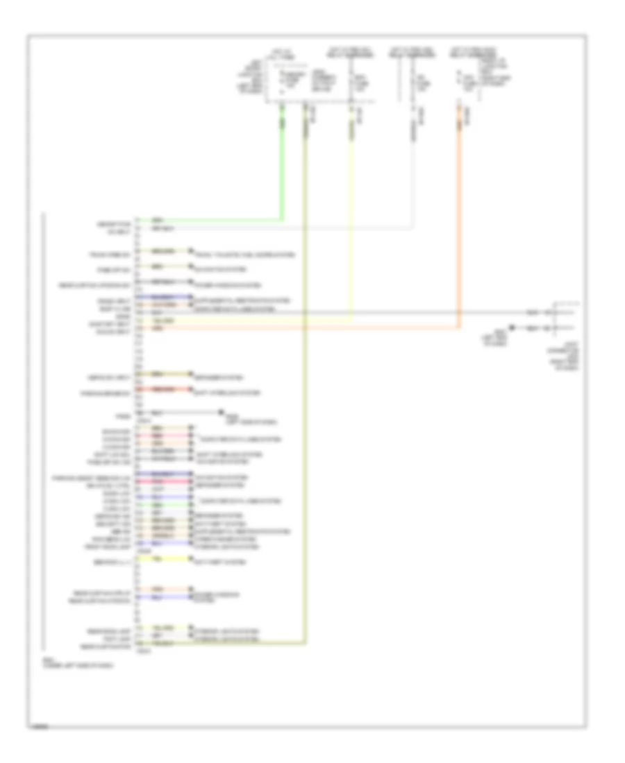
Body Control Module Wiring Diagram for Hyundai Equus Ultimate 2014
 https://portal-diagnostov.com/license.html
Automotive Electricians Portal FZCO
Automotive Electricians Portal FZCO
https://portal-diagnostov.com/license.html
https://portal-diagnostov.com/license.html
Automotive Electricians Portal FZCO
Automotive Electricians Portal FZCOList of elements for Body Control Module Wiring Diagram for Hyundai Equus Ultimate 2014:
- Acc fuse 10a
- Acc/on input
- Anti-theft system
- B-can high
- B-can low
- Bcm (under left side of dash)
- Bcm fuse 10a
- Body k-line
- C-can high
- C-can low
- Computer data lines system
- Crash input
- Defog sw ind
- Defog sw input
- Defogger system
- Foot lamp
- Front room lamp
- Gm01 (left end of dash)
- Gm05 (left side of dash)
- Hot at all times
- Hot w/ pdm (acc) relay energized
- Hot w/ pdm (ig1) relay energized
- Hot w/ pdm (ig2) relay energized
- I/p-lhf
- I/p-lhg
- I/p-rha
- I/p-rhd
- Ig2 fuse 10a
- Interior lights system
- Joint connector jm03 (right end of dash)
- Leak current autocut device
- Left smart junction box (left end of dash)
- M-can high
- M-can low
- M32-a
- M32-b
- M32-c
- Memory fuse 10a
- Memory pwr
- Navigation system
- On input
- On/start input
- P-gnd
- Parking assist sens sig (lin)
- Parking brake sw
- Pass off sw
- Pass off sw ind
- Pnk
- Power windows system
- Rain sens (lin)
- Rear curtain mtr dwn
- Rear curtain mtr up
- Rear curtain pwr
- Rear curtain up/down sw
- Rear room lamp
- Red
- Right i/p junction box (right end of dash)
- Rr htd rly ctrl
- S-gnd
- Sbr ind
- Security sig
- Shift interlock system
- Shift lck sol
- Ssb ring ill (-)
- Trunk open sw
- Trunk, tailgate, fuel doors system
- Wiper/washer system
Front Area Module Wiring Diagram for Hyundai Equus Ultimate 2014
 https://portal-diagnostov.com/license.html
Automotive Electricians Portal FZCO
Automotive Electricians Portal FZCO
https://portal-diagnostov.com/license.html
https://portal-diagnostov.com/license.html
Automotive Electricians Portal FZCO
Automotive Electricians Portal FZCOList of elements for Front Area Module Wiring Diagram for Hyundai Equus Ultimate 2014:
- (left front of
- B-can high
- B-can low
- B/alarm horn
- Computer data lines system
- Door locks & anti-theft systems
- Drl gnd
- E/r junction box (right rear of engine compt)
- E/r-e1a
- E/r-e1b
- E/r-e2a
- Em21
- Engine compt)
- Ext buzzer
- Exterior lights system
- Fam
- Fam 1 (b+) fuse 40a
- Fam 2 (b+) fuse 40a
- Fam-a
- Fam-b
- Fam-c
- Front fog lamp rh
- Front fog lp lh
- Ge03
- Ge04 (lower right rear of engine compt)
- Gm01 (left end of dash)
- H/lamp rly ctrl
- Headlights system
- Hot at all times
- Hot w/ pdm (ig1) relay energized
- I/p-lhe
- I/p-lhf
- Ill (+)
- Interior lights system
- Ips 3 (1ch)
- Joint connector je02 (under left end of dash)
- Joint connector jm01 (center of dash)
- Joint connector jm03 (right end of dash)
- Left smart junction box (left end of dash)
- Lh headlamp hi
- Lh tail lp
- Memory power
- Memory pwr
- Module 4 fuse 10a
- On/start input
- P-gnd
- Pnk
- Rear turn sig lamp fail lh
- Rear turn sig lamp fail rh
- Red
- Rh headlamp hi
- Rh tail lp
- Room lamp rly ctrl
- S-gnd
- Turn sig lamp lh front
- Turn sig lamp lh rear
- Turn sig lamp rh front
- Turn sig lamp rh rear
IPS Control Module Wiring Diagram for Hyundai Equus Ultimate 2014
 https://portal-diagnostov.com/license.html
Automotive Electricians Portal FZCO
Automotive Electricians Portal FZCO
https://portal-diagnostov.com/license.html
https://portal-diagnostov.com/license.html
Automotive Electricians Portal FZCO
Automotive Electricians Portal FZCOList of elements for IPS Control Module Wiring Diagram for Hyundai Equus Ultimate 2014:
- (left end of dash) left smart junction box
- Anti-lock brakes system
- B-can high
- B-can low
- Backup gnd
- Body k-line
- Brake fluid switch
- Computer data lines system
- Door locks & anti-theft systems
- Driver seat belt
- Engine room fuse & relay box (left side of engine compt)
- Ess sig
- Exterior lights system
- Gf03 (left "c" pillar)
- Gm01 (left end of dash)
- Ground distribution system
- Hazard switch
- Hazard symbol
- Hood switch
- Hot at all times
- Hot in on
- I/p power lh fuse 80a
- I/p-lhb
- I/p-lhd
- I/p-lhe
- I/p-lhf
- I/p-lhg
- I/p-rhd
- Ig2
- Instrument cluster system
- Interior lights system
- Ips 3 (1ch)
- Ips 3 control
- Ips control module
- Joint connector jf01
- Joint connector jm05 (center of dash)
- Leak current autocut control relay
- Leak current autocut control sw
- Leak current autocut device
- Leak current autocut relay
- Leak current autocut switch
- Left front door sw
- Left rear door sw
- Mcu gnd
- Memory power
- Mf11
- Module fuse 10a
- Off
- Passenger seat belt
- Pnk
- Power distribution system
- Power gnd
- Right front door sw
- Right i/p junction box (right end of dash)
- Right rear door sw
- Trunk door lck switch
- Trunk lid switch
- Trunk open actuator
- Trunk room lamp
- Trunk switch
- Trunk, tailgate, fuel doors system
COMPUTER DATA LINES
Computer Data Lines Wiring Diagram (1 of 4) for Hyundai Equus Ultimate 2014
 https://portal-diagnostov.com/license.html
Automotive Electricians Portal FZCO
Automotive Electricians Portal FZCO
https://portal-diagnostov.com/license.html
https://portal-diagnostov.com/license.html
Automotive Electricians Portal FZCO
Automotive Electricians Portal FZCOList of elements for Computer Data Lines Wiring Diagram (1 of 4) for Hyundai Equus Ultimate 2014:
- (+)
- (left end of dash)
- (left rear of engine compt) electronic control wiper module
- (left side of dash) steering tilt & telescopic module
- (not used)
- (or red)
- 5:5 seat
- 6:4 seat
- Active headrest sensor module (under center console)
- Amp
- Analog clock
- Around view unit
- Av & navigation head unit
- B-can hi
- B-can lo
- C-can hi
- C-can lo
- Camera module (right center of dash)
- Clockspring
- Data link connector (below left side of dash)
- Driver active headrest (in driver's seat back)
- Ef31
- Em31
- Em41
- F03-a
- Front dis switch (center of floor console)
- Front monitor (w/ av)
- Fs11
- Fs21
- Fs31
- Gf02 (left "b" pillar)
- Gm01
- Gm06 (left end of dash)
- Hot at all times
- I/p-lhf
- I/p-lhg
- Ips control module
- J/c jm02 (center of dash)
- K-line
- Leak current autocut device
- Left down steering wheel remote control
- Left rear monitor
- M-can hi
- M-can lo
- M03-b
- M04-b
- M52-a
- M93-dl1
- M93-dl2
- Memory fuse 10a
- Mf11
- Mf21
- Nca
- Pnk
- Rear audio switch
- Red
- Right rear monitor
- Right up steering wheel remote control
- Smart junction box
- Ss31
- Steering wheel
- W/ avm
- W/o avm
Computer Data Lines Wiring Diagram (2 of 4) for Hyundai Equus Ultimate 2014
 https://portal-diagnostov.com/license.html
Automotive Electricians Portal FZCO
Automotive Electricians Portal FZCO
https://portal-diagnostov.com/license.html
https://portal-diagnostov.com/license.html
Automotive Electricians Portal FZCO
Automotive Electricians Portal FZCOList of elements for Computer Data Lines Wiring Diagram (2 of 4) for Hyundai Equus Ultimate 2014:
- (top left side of dash) j/c jm11
- (under left side of dash) smart key control module
- 5:5 seat
- 6:4 seat
- B-can hi
- B-can lo
- C-can hi
- C-can lo
- C200-a
- C200-at
- C200-k
- Ccp-can hi
- Ccp-can lo
- D51-c
- D61-c
- Dd11
- Dd21
- Driver door module (driver's door)
- Driver ims control module (under driver's seat)
- E/r junction box (right rear of engine compt)
- E/r-e1b
- Ec21
- Ecm (left rear of engine compt)
- Em21
- Em31
- Fam
- Fam-b
- Fd11
- Fd21
- Fs11
- Fs41
- Injector drive box (left rear of engine compt)
- Instrument cluster
- J/c jf21 (left "b" pillar)
- K-line
- M-can hi
- M-can lo
- M30-a
- M30-b
- Multi-function switch
- Passenger door module (front passenger's door)
- Pnk
- Power trunk lid control module (left front of trunk)
- Rear console switch
- Red
- Relax module (bottom of passenger's seat)
- S16-d
- S27-b
- S37-b
- S70-c
- Spd o/p
- Ss41
- Tcm (left rear of engine compt)
Computer Data Lines Wiring Diagram (3 of 4) for Hyundai Equus Ultimate 2014
 https://portal-diagnostov.com/license.html
Automotive Electricians Portal FZCO
Automotive Electricians Portal FZCO
https://portal-diagnostov.com/license.html
https://portal-diagnostov.com/license.html
Automotive Electricians Portal FZCO
Automotive Electricians Portal FZCOList of elements for Computer Data Lines Wiring Diagram (3 of 4) for Hyundai Equus Ultimate 2014:
- (center of dash) j/c jm01
- (center of dash) j/c jm12
- (not used)
- (on steering column) steering angle sensor
- (right center of dash) mts module
- (under center console) srs control module
- (under left side of dash) bcm
- B-can hi
- B-can lo
- C-can hi
- C-can lo
- E/r junction box (right rear of engine compt)
- E/r-ctb
- E/r-e2b
- E11-u
- Ee21
- Ee31
- Ehps module (under right headlight)
- Em21
- Esc control module (left front of engine compt)
- Head-up display
- Hi c-can
- J/c jc23 (rear of engine)
- J/c je01 (engine room fuse & relay box)
- J/c je04 (under right headlight)
- J/c je11 (under right side of radiator)
- J/c jm03 (right end of dash)
- K-line
- Lo c-can
- M-can hi
- M-can lo
- M06
- M11
- M32-a
- M32-b
- M53
- Mf11
- Nca
- Premium
- Red
- Smart cruise control module (lower front of radiator)
- Standard
Computer Data Lines Wiring Diagram (4 of 4) for Hyundai Equus Ultimate 2014
 https://portal-diagnostov.com/license.html
Automotive Electricians Portal FZCO
Automotive Electricians Portal FZCO
https://portal-diagnostov.com/license.html
https://portal-diagnostov.com/license.html
Automotive Electricians Portal FZCO
Automotive Electricians Portal FZCOList of elements for Computer Data Lines Wiring Diagram (4 of 4) for Hyundai Equus Ultimate 2014:
- (center of dash) a/c control module
- (front center of roof) ldws camera module
- (left side of engine compt)
- (right center of dash) adaptive front light module
- (right center of dash) tire pressure monitoring control module
- (right front of roof trim) j/c jr02
- C-can hi
- C-can lo
- Driver pre-safe seat belt (base of left "b" pillar)
- E/r fuse & relay box
- E/r junction box (right rear of engine compt)
- E/r-e2b
- Ecs control module (left side of trunk)
- Ef31
- Electronic parking brake control module (front of trunk)
- Esc 1 fuse 40a
- Esc 2 fuse 40a
- Esc fuse 10a
- F01-a
- Ff01
- Ff02
- Ff04
- Fr21
- Fr31
- Fuel pump control module (left side of trunk)
- Ge02 (right kick panel)
- Gf02 (left "b" pillar)
- Hot at all times
- Hot in on or start
- J/c je03 (under left end of dash)
- J/c jf04 (left side of trunk)
- J/c jf13 (right "b" pillar)
- J/c jf14 (right "c" pillar)
- J/c jf15 (right side of trunk)
- J/c jf21 (left "b" pillar)
- J/c jf22 (right front of trunk)
- K-line
- M07-b
- Mf21
- Multipurpose check connector
- Passenger pre-safe seat belt (right "b" pillar)
- Pods module (under front passenger's seat)
- Red
- Right blind spot detection radar (right rear corner of vehicle)
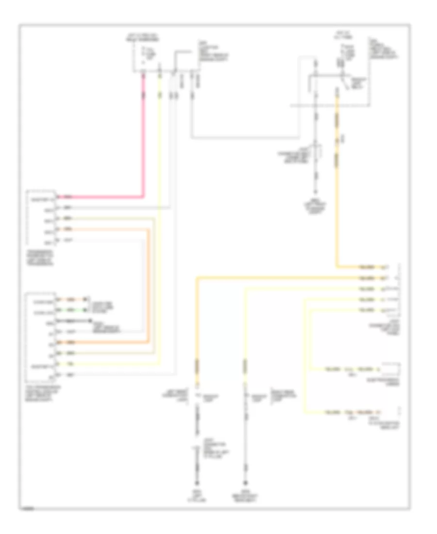
COOLING FAN
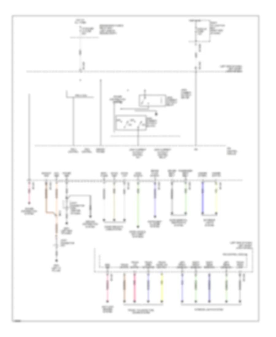
Cooling Fan Wiring Diagram for Hyundai Equus Ultimate 2014
 https://portal-diagnostov.com/license.html
Automotive Electricians Portal FZCO
Automotive Electricians Portal FZCO
https://portal-diagnostov.com/license.html
https://portal-diagnostov.com/license.html
Automotive Electricians Portal FZCO
Automotive Electricians Portal FZCOList of elements for Cooling Fan Wiring Diagram for Hyundai Equus Ultimate 2014:
- (left front of engine compt) ge01
- C-can hi
- C-can lo
- C/fan fuse 70a
- C/fan relay
- C200-a
- C200-k
- Computer data lines system
- Condenser fan
- Cooling fan controller (left front of engine compt)
- Current detecting
- E/r fuse & relay box (left side of engine compt)
- E/r-cta
- E/r-e2a
- E05-a
- E05-b
- Ec21
- Ecm (left rear of engine compt)
- Ects gnd
- Ects sig
- Ecu fuse 30a
- Ecu relay
- Ecu rly ctrl
- Engine coolant temperature sensor (front of right cylinder head)
- Engine fan/pwm
- Engine room junction box (right rear of engine compt)
- Ge01 (left front of engine compt)
- Ge03 (left front of engine compt)
- Hot at all times
- J/c je02 (under left end of dash)
- Nca
- Power conditioning
- Pwn driver
- Radiator fan
- Red
- Sensor 2 fuse 10a
- Signal processing
CRUISE CONTROL
Cruise Control Wiring Diagram (1 of 2) for Hyundai Equus Ultimate 2014
 https://portal-diagnostov.com/license.html
Automotive Electricians Portal FZCO
Automotive Electricians Portal FZCO
https://portal-diagnostov.com/license.html
https://portal-diagnostov.com/license.html
Automotive Electricians Portal FZCO
Automotive Electricians Portal FZCOList of elements for Cruise Control Wiring Diagram (1 of 2) for Hyundai Equus Ultimate 2014:
- (base of right "c" pillar) j/c jf12
- (engine room fuse & relay box) j/c je01
- (left side of dash) stop signal electronic module
- (lower right rear of engine compt) ge04
- Accel pedal position sensor (behind accelerator pedal assembly)
- Aps 1 gnd
- Aps 1 sig
- Aps 1 sply
- Aps 2 gnd
- Aps 2 sig
- Brk sw
- C-can hi
- C-can lo
- C200-a
- C200-k
- Close w/ brake pedal depressed
- Computer data lines system
- Cruise (b+) fuse 10a
- Cruise (ig1) fuse 10a
- E/r junction box (right rear of engine compt)
- E/r-cta
- E/r-ctb
- E/r-e2a
- E/r-e2b
- Ec21
- Ecm (left rear of engine compt)
- Ecu (ig1) fuse 10a
- Ee21
- Ef11
- Em31
- Engine controls system
- Esc fuse 10a
- Etc dc motor (+)
- Etc dc motor (-)
- Etc motor & throttle position sensor (throttle body)
- Gc201 (left rear of engine compt)
- Gnd
- Ground
- Hot at all times
- Hot w/ pdm (ig1) relay energized
- I/p-lhc
- I/p-lhe
- J/c je02 (under left end of dash)
- Left smart junction box (left end of dash)
- M30-b
- Memory pwr
- Module fuse 10a
- Motor
- On/st i/p
- On/st in
- Open w/ brake pedal depressed
- Pnk
- Power distribution system
- Red
- Sens sply
- Smart cruise control module (w/ scc) (lower front of radiator)
- Smart key control module (under left side of dash)
- Stop lamp fuse 10a
- Stop lamp switch (top of brake pedal assembly)
- Stp lmp sig
- Stp lmp sw
- Throttle position sensor
- Tps gnd
- Tps sig 1
- Tps sig 2
Cruise Control Wiring Diagram (2 of 2) for Hyundai Equus Ultimate 2014
 https://portal-diagnostov.com/license.html
Automotive Electricians Portal FZCO
Automotive Electricians Portal FZCO
https://portal-diagnostov.com/license.html
https://portal-diagnostov.com/license.html
Automotive Electricians Portal FZCO
Automotive Electricians Portal FZCOList of elements for Cruise Control Wiring Diagram (2 of 2) for Hyundai Equus Ultimate 2014:
- (on left front wheel hub assembly) left front wheel sensor
- (on right front wheel hub assembly) right front wheel sensor
- +ecu
- 1.5v/1.275v reg
- 1.8v reg
- 3.3v reg
- 5v reg
- 7 inches tft lcd type
- Agnd
- B-can hi
- B-can lo
- Brk lmp sw
- Brk pedal sw
- C-can high
- C-can low
- C-can transceiver
- Clock spring
- Cluster fuse 10a
- Computer data lines system
- Cruise
- Cruise ind
- E/r fuse & relay box (left side of engine compt)
- Ef21
- Ef31
- Esc control module (left front of engine compt)
- Esc unit
- Fl sig
- Fl vcc
- Fr sig
- Fr vcc
- Full tft lcd type
- Ge02 (right kick panel)
- Gf03 (left "c" pillar)
- Gm01 (left end of dash)
- Gm06 (left end of dash)
- Gnd
- Ground distribution system
- High
- High b-can
- Hot at all times
- Hot w/ pdm (ig1) relay energized
- H_iil(+)
- H_iil(-)
- I/p-lhd
- I/p-lhf
- Instrument cluster
- Ips 3 (1ch)
- Ips control module
- J/c jf01 (left "c" pillar)
- J/c jm01 (center of dash)
- J/c jm03 (right end of dash)
- Joint connector jm05 (center of dash)
- Left i/p power fuse 80a
- Left rear wheel sensor
- Left smart junction box (left end of dash)
- Left steering remote control switch (down)
- Low
- Low b-can
- M-can transceiver
- M13
- M91
- M93-dl1
- M93-dr
- Memory pwr
- Mf11
- Micom
- Nca
- Pnk
- Power distribution system
- Premium
- Pwr gnd
- Red
- Right rear wheel sensor
- Right steering remote control switch (down)
- Rl sig
- Rl vcc
- Rr sig
- Rr vcc
- S gnd
- Set
- Set ind
- Signal3
- Standard
- Steering wheel
- Tft lcd
- Tft lcd driver
DEFOGGERS
Defoggers Wiring Diagram for Hyundai Equus Ultimate 2014
 https://portal-diagnostov.com/license.html
Automotive Electricians Portal FZCO
Automotive Electricians Portal FZCO
https://portal-diagnostov.com/license.html
https://portal-diagnostov.com/license.html
Automotive Electricians Portal FZCO
Automotive Electricians Portal FZCOList of elements for Defoggers Wiring Diagram for Hyundai Equus Ultimate 2014:
- A/c control module (center of dash)
- A/con fuse 7.5a
- Auto defogger sensor (top center of windshield)
- Bcm (under left side of dash)
- C-can high
- C-can low
- Close
- Computer data lines system
- Dd11
- Dd21
- Defogger
- Defogger actuator
- Defogger actuator (right side of hvac unit)
- Defogger sw i/p
- Defogger sw ind
- Defogger switch
- Deicer fuse 15a
- Deicer relay
- Driver power outside mirror
- E/r junction box (right rear of engine compt)
- E/r-e1b
- E/r-e2a
- E/r-e2b
- Ef21
- Em21
- F/b
- Fd11
- Fd21
- Fr21
- Front deicer
- Ge07 (lower right rear of engine compt)
- Gf01 (left kick panel)
- Gf05 (right kick panel)
- Gm02 (left side
- Ground
- Hot at all times
- Hot in on
- Htd mirr fuse 10a
- Humidity snsr
- I/p-rhb
- Ind
- Joint connector uma
- Joint connector umb
- M07-a
- M07-b
- M07-c
- M32-a
- M32-b
- Mf21
- Nca
- Of dash)
- Off
- On input
- Open
- Passenger power outside mirror
- Pnk
- Quarter panel ground
- Rear
- Relay
- Right i/p junction box (right end of dash)
- Rr htd
- Rr htd fuse 40a
- Rr htd rly ctrl
- Snsr (+)
- Snsr (-)
- Snsr gnd
- Snsr pwr
ELECTRONIC POWER STEERING
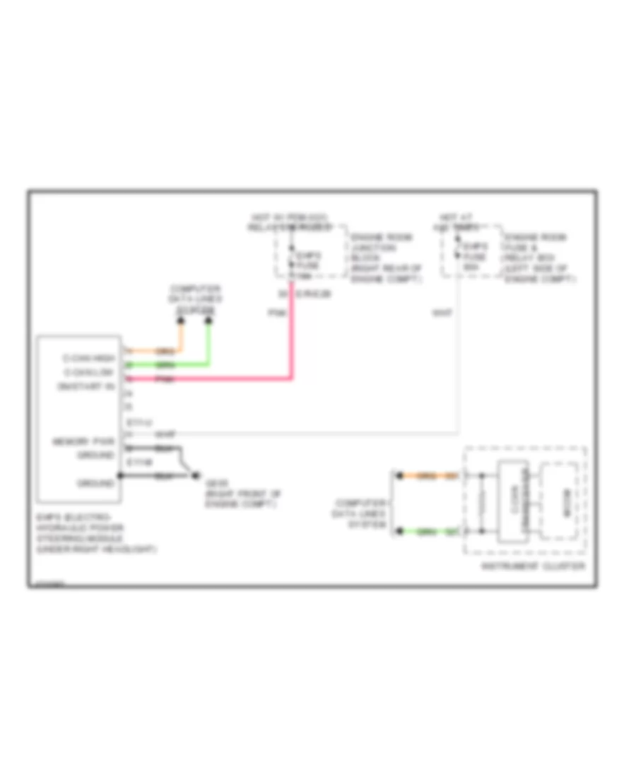
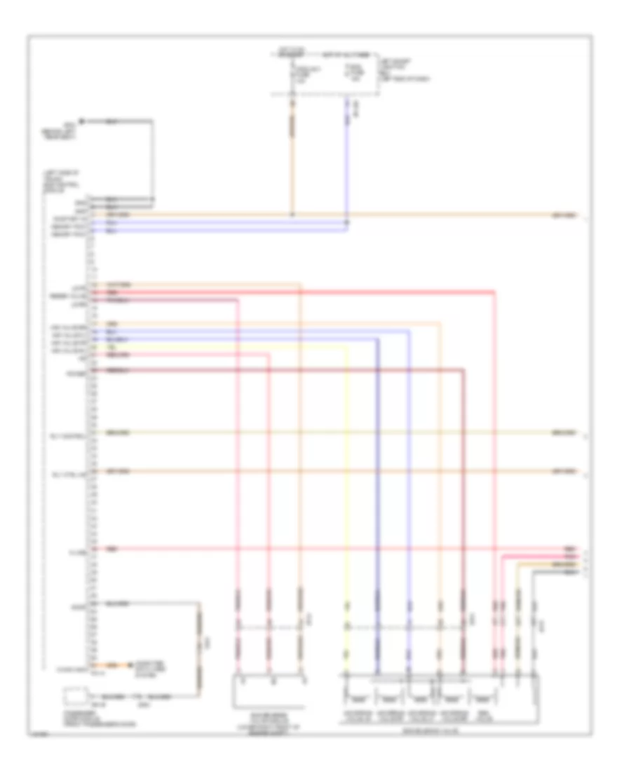
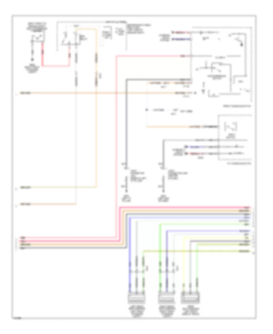
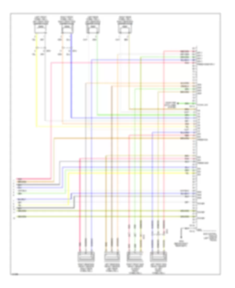
Electronic Power Steering Wiring Diagram for Hyundai Equus Ultimate 2014
 https://portal-diagnostov.com/license.html
Automotive Electricians Portal FZCO
Automotive Electricians Portal FZCO
https://portal-diagnostov.com/license.html
https://portal-diagnostov.com/license.html
Automotive Electricians Portal FZCO
Automotive Electricians Portal FZCOList of elements for Electronic Power Steering Wiring Diagram for Hyundai Equus Ultimate 2014:
- C-can high
- C-can low
- C-can transceiver
- Computer data lines system
- E/r-e2b
- E11-m
- E11-u
- Ehps (electro- hydraulic power steering) module (under right headlight)
- Ehps fuse 10a
- Ehps fuse 80a
- Engine room fuse & relay box (left side of engine compt)
- Engine room junction block (right rear of engine compt)
- Ge05 (right front of engine compt)
- Ground
- Hot at all times
- Hot w/ pdm (ig1) relay energized
- Instrument cluster
- Memory pwr
- Micom
- On/start in
- Pnk
ELECTRONIC SUSPENSION
Electronic Suspension Wiring Diagram (1 of 3) for Hyundai Equus Ultimate 2014
 https://portal-diagnostov.com/license.html
Automotive Electricians Portal FZCO
Automotive Electricians Portal FZCO
https://portal-diagnostov.com/license.html
https://portal-diagnostov.com/license.html
Automotive Electricians Portal FZCO
Automotive Electricians Portal FZCOList of elements for Electronic Suspension Wiring Diagram (1 of 3) for Hyundai Equus Ultimate 2014:
- (left side of trunk) ecs control module
- Air spring valve lf
- Air spring valve lr
- Air spring valve rf
- Air spring valve rr
- Air valve fl
- Air valve fr
- Air valve rl
- Air valve rr
- C-can high
- Computer data lines system
- D61-b
- Dd21
- Door
- Ecs fuse 15a
- Ecs reverse valve module (lower right front of engine compt)
- Ecs solenoid valve
- Ef31
- Ef41
- Ef51
- F01-a
- Fd21
- Gf04 (behind left rear seat)
- Gnd
- Hot at all times
- Hot in on or start
- I/p-lhc
- K-line
- Left smart junction box (left end of dash)
- Ls fr
- Ls rr
- Memory pow
- Module 3 fuse 10a
- On/start in
- Passenger door module (front passenger's door)
- Pnk
- Power
- Red
- Res valve
- Reser valve
- Rly control
- Rly ctrl hs
Electronic Suspension Wiring Diagram (2 of 3) for Hyundai Equus Ultimate 2014
 https://portal-diagnostov.com/license.html
Automotive Electricians Portal FZCO
Automotive Electricians Portal FZCO
https://portal-diagnostov.com/license.html
https://portal-diagnostov.com/license.html
Automotive Electricians Portal FZCO
Automotive Electricians Portal FZCOList of elements for Electronic Suspension Wiring Diagram (2 of 3) for Hyundai Equus Ultimate 2014:
- (not used)
- (right front of engine compt) ecs compressor motor
- 12v
- A/t console switch
- Air suspension switch
- Alt fuse 200a
- Cpu
- Ecs 2 switch
- Ecs fuse 40a
- Ecs relay
- Ef41
- Ef51
- Engine room fuse & relay box (left side of engine compt)
- F11-a
- F11-b
- Front console switch
- Ge08 (right front of engine compt)
- Gf03 (left "c" pillar)
- Gm01 (left end of dash)
- Hot at all times
- Illum
- Interior lights system
- Joint connector jf02 (base of left "c" pillar)
- Joint connector jm05 (center of dash)
- K-line ic
- Left front ecs g-sensor (left front of engine compt)
- Mf11
- Mm02
- Nca
- Pnk
- Rear ecs g-sensor (left front side of trunk)
- Red
- Right front ecs g-sensor (right front of engine compt)
Electronic Suspension Wiring Diagram (3 of 3) for Hyundai Equus Ultimate 2014
 https://portal-diagnostov.com/license.html
Automotive Electricians Portal FZCO
Automotive Electricians Portal FZCO
https://portal-diagnostov.com/license.html
https://portal-diagnostov.com/license.html
Automotive Electricians Portal FZCO
Automotive Electricians Portal FZCOList of elements for Electronic Suspension Wiring Diagram (3 of 3) for Hyundai Equus Ultimate 2014:
- (left front wheel well) left front ecs damper valve
- (left rear wheel well) left rear ecs damper valve
- (right front wheel well) right front ecs damper valve
- (right rear wheel well) right rear ecs damper valve
- C-can low
- Computer data lines system
- Ecs control module (left side of trunk)
- Ef31
- Ef41
- Ef51
- F01-a
- F01-b
- F01-g
- Gf08 (behind right rear seat)
- Gnd
- Left front ecs height sensor (in left front wheelwell)
- Left rear ecs height sensor (left rear wheelwell)
- Pnk
- Power
- Press gnd
- Press sig
- Press snsr sply
- Red
- Right front ecs height sensor (in right front wheelwell)
- Right rear ecs height sensor (right rear wheelwell)
- Sig
- Sply
ENGINE PERFORMANCE
5.0L
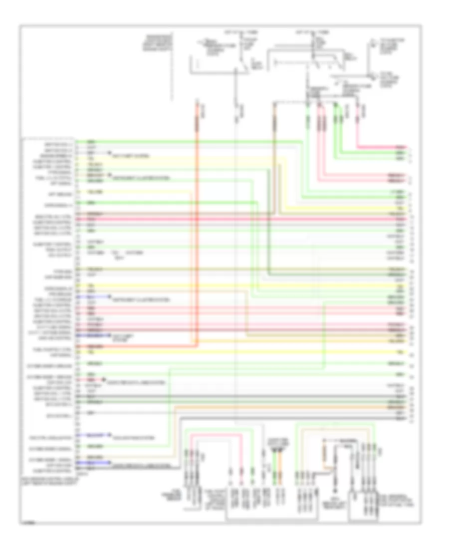
5.0L, Engine Performance Wiring Diagram (1 of 6) for Hyundai Equus Ultimate 2014
 https://portal-diagnostov.com/license.html
Automotive Electricians Portal FZCO
Automotive Electricians Portal FZCO
https://portal-diagnostov.com/license.html
https://portal-diagnostov.com/license.html
Automotive Electricians Portal FZCO
Automotive Electricians Portal FZCOList of elements for 5.0L, Engine Performance Wiring Diagram (1 of 6) for Hyundai Equus Ultimate 2014:
- (left rear of engine compt)
- Anti-theft system
- Apt ground
- Apt signal
- C-can hi
- C-can l0
- C200-a
- Ccp can high
- Ccp can low
- Ccv output
- Ckps signal a
- Ckps signal b
- Computer data lines system
- Cooling fans system
- Cvvt 1 (intake) signal
- Cvvt 2 (ex) signal
- E/r-cta
- E/r-e1a
- E/r-e2a
- Ec41
- Ecm (engine control module)
- Ecu fuse 30a
- Ecu relay
- Ef11
- Eng ctrl rly ctrl
- Engine room junction box (right rear of engine compt)
- Engine speed in
- Etc motor (+)
- Etc motor (-)
- F/ pump relay
- F/pump fuse 20a
- Fan ctrl module pwm
- Ff03
- Fps gnd
- Fps ground
- Fps vout
- Fps vs
- From sensor 3 fuse (diagram 5 of 6)
- Ftps gnd
- Ftps signal
- Fuel lvl in (middle)
- Fuel lvl in (total)
- Fuel pressure sensor
- Fuel pump
- Fuel pump control module (left side of trunk)
- Fuel pump rly ctrl
- Fuel pump u
- Fuel pump v
- Fuel pump w
- Gf04 (behind left rear seat)
- Gnd
- Hot at all times
- Ignition coil 1 ctrl
- Ignition coil 2 ctrl
- Ignition coil 3
- Ignition coil 4 ctrl
- Ignition coil 5 ctrl
- Ignition coil 6
- Ignition coil 7 ctrl
- Ignition coil 8 ctrl
- Immo ind control
- Injector 1 control
- Injector 2 control
- Injector 3 control
- Injector 4 control
- Injector 5 control
- Injector 6 control
- Injector 7 control
- Injector 8 control
- Instrument cluster system
- Map signal
- Map snsr gnd
- Nca
- Oxygen snsr 1 ground
- Oxygen snsr 1 signal
- Oxygen snsr 2 ground
- Oxygen snsr 2 signal
- Pcsv output
- Pnk
- Pump unit u
- Pump unit v
- Pump unit w fuel sender & fuel pump motor (top of fuel tank)
- Red
- Rly on i/p
- Sensor 2 fuse 10a
- Snsr gnd fuel pres
- Snsr vout fuel pres
- Snsr vs fuel pres
- To ign coil fuse (diagram 3 of 6)
- To injector (b+) fuse (diagram 2 of 6)
- To sensor 3 fuse (diagram 5 of 6)
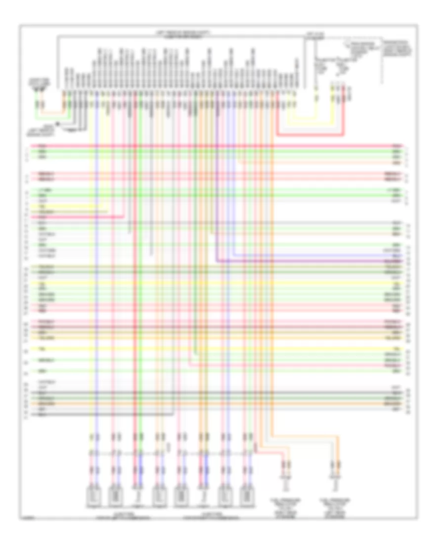
5.0L, Engine Performance Wiring Diagram (2 of 6) for Hyundai Equus Ultimate 2014
 https://portal-diagnostov.com/license.html
Automotive Electricians Portal FZCO
Automotive Electricians Portal FZCO
https://portal-diagnostov.com/license.html
https://portal-diagnostov.com/license.html
Automotive Electricians Portal FZCO
Automotive Electricians Portal FZCOList of elements for 5.0L, Engine Performance Wiring Diagram (2 of 6) for Hyundai Equus Ultimate 2014:
- (left rear of engine compt) injector drive box
- C-can high
- C-can low
- Cc21
- Cc22
- Computer data lines system
- E/r-ctb
- Engine room junction box (right rear of engine compt)
- From engine control relay (diagram 1 of 6)
- Fuel pressure regulator valve 1 (right rear of engine)
- Fuel pressure regulator valve 2 (left rear of engine)
- Gc201 (left rear of engine compt)
- Ground
- Hot in on or start
- Injector (b+) fuse 15a
- Injector (ig1) fuse 10a
- Injector 1 sig
- Injector 1 snsr gnd
- Injector 2 sig
- Injector 2 snsr gnd
- Injector 3 sig
- Injector 3 snsr gnd
- Injector 4 sig
- Injector 4 snsr gnd
- Injector 5 sig
- Injector 5 snsr gnd
- Injector 6 sig
- Injector 6 snsr gnd
- Injector 7 sig
- Injector 7 snsr gnd
- Injector 8 sig
- Injector 8 snsr gnd
- Injector control 1
- Injector control 2
- Injector control 3
- Injector control 4
- Injector control 5
- Injector control 6
- Injector control 7
- Injector control 8
- Injectors (top of left cylinder bank)
- Injectors (top of right cylinder bank)
- Msv1 high
- Msv1 low
- Msv1 on
- Msv1 sel0
- Msv1 sel1
- Msv2 high
- Msv2 low
- Msv2 on
- Msv2 sel0
- Msv2 sel1
- On/start input
- Pnk
- Red
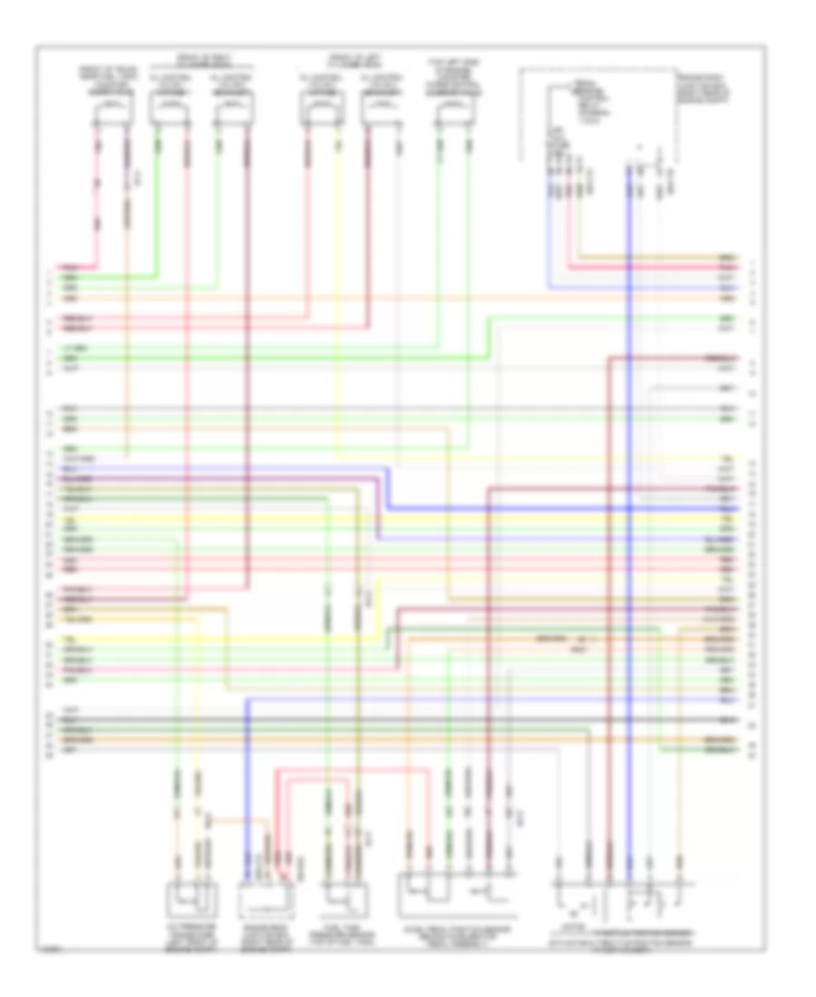
5.0L, Engine Performance Wiring Diagram (3 of 6) for Hyundai Equus Ultimate 2014
 https://portal-diagnostov.com/license.html
Automotive Electricians Portal FZCO
Automotive Electricians Portal FZCO
https://portal-diagnostov.com/license.html
https://portal-diagnostov.com/license.html
Automotive Electricians Portal FZCO
Automotive Electricians Portal FZCOList of elements for 5.0L, Engine Performance Wiring Diagram (3 of 6) for Hyundai Equus Ultimate 2014:
- (front of left cylinder head)
- (front of right cylinder head)
- (front of trunk, near fuel tank) canister close valve
- (top left side of engine) canister purge control solenoid valve
- 1 of 6)
- A/c pressure transducer (left front of engine compt)
- Accel pedal position sensor (behind accelerator pedal assembly)
- Control relay (diagram
- E/r-cta
- E/r-ctb
- E/r-e2a
- Ec21
- Ef11
- Engine room junction box (right rear of engine compt)
- Etc motor & throttle position sensor (throttle body)
- From engine b
- Fuel tank pressure sensor (top of fuel tank)
- Ign coil fuse 20a
- Motor
- Oil control valve 1 (intake)
- Oil control valve 2 (exhaust)
- Oil control valve 3 (intake)
- Oil control valve 4 (exhaust)
- Pnk
- Red
- Throttle position sensor
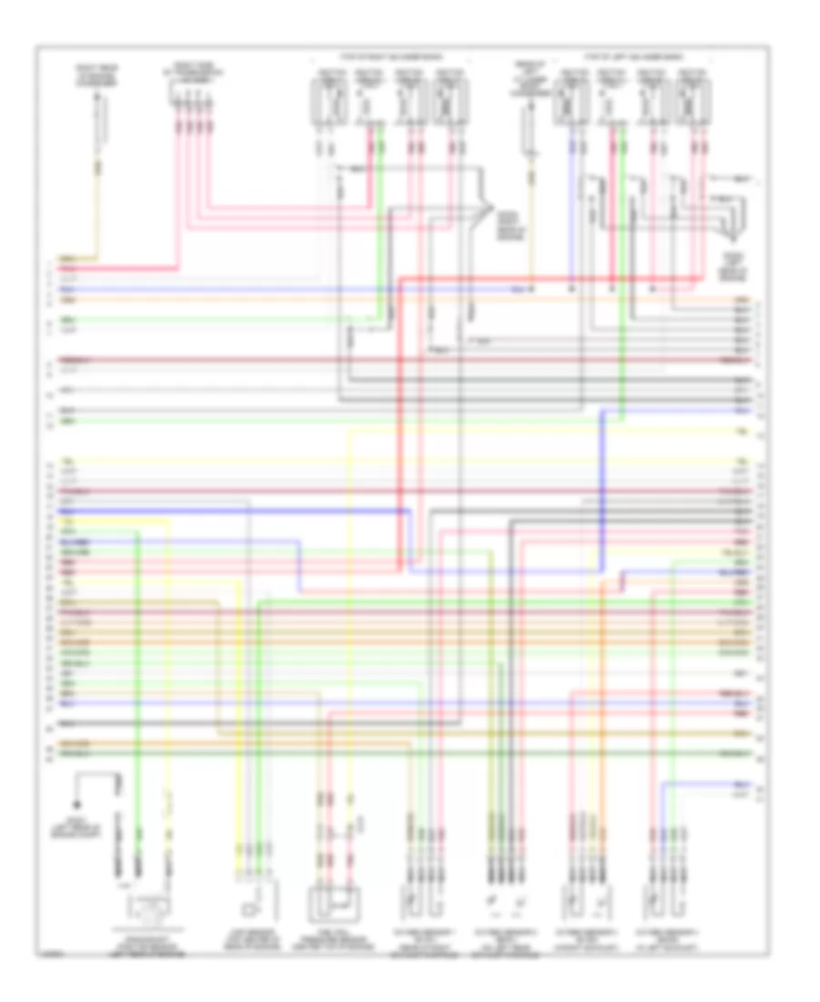
5.0L, Engine Performance Wiring Diagram (4 of 6) for Hyundai Equus Ultimate 2014
 https://portal-diagnostov.com/license.html
Automotive Electricians Portal FZCO
Automotive Electricians Portal FZCO
https://portal-diagnostov.com/license.html
https://portal-diagnostov.com/license.html
Automotive Electricians Portal FZCO
Automotive Electricians Portal FZCOList of elements for 5.0L, Engine Performance Wiring Diagram (4 of 6) for Hyundai Equus Ultimate 2014:
- (rear of left cylinder bank) condenser
- (right rear of engine) condenser
- (right side of transmission) j/c jc22
- (top of left cylinder bank)
- (top of right cylinder bank)
- Cc21
- Crankshaft position sensor (left rear of engine)
- Fuel rail pressure sensor (center top of engine)
- Gc201 (left rear of engine compt)
- Gc202 (right rear of engine)
- Gc203 (left rear of engine)
- Ignition coil 1
- Ignition coil 2
- Ignition coil 3
- Ignition coil 4
- Ignition coil 5
- Ignition coil 6
- Ignition coil 7
- Ignition coil 8
- Map sensor (top center of rear of engine)
- Nca
- Oxygen sensor 1 (b1/s1) (rear of right exhaust manifold)
- Oxygen sensor 2 (b2/s1) (on left rear exhaust manifold)
- Oxygen sensor 3 (b1/s2) (in right exhaust)
- Oxygen sensor 4 (b2/s2) (in left exhaust)
- Pnk
- Red
5.0L, Engine Performance Wiring Diagram (5 of 6) for Hyundai Equus Ultimate 2014
 https://portal-diagnostov.com/license.html
Automotive Electricians Portal FZCO
Automotive Electricians Portal FZCO
https://portal-diagnostov.com/license.html
https://portal-diagnostov.com/license.html
Automotive Electricians Portal FZCO
Automotive Electricians Portal FZCOList of elements for 5.0L, Engine Performance Wiring Diagram (5 of 6) for Hyundai Equus Ultimate 2014:
- (left rear of engine)
- (rear of engine) j/c jc21
- Alt fr
- Anti- theft system
- Aps 1 ground
- Aps 2 ground
- Aps 2 signal
- Battery power
- Brakes system anti-lock
- C-can high
- C-can low
- C200-k
- Camshaft position sensor (bank 2 exhaust)
- Camshaft position sensor (bank 2 intake)
- Cluster fuse 10a
- Cmps bank1 signal
- Cmps bank2 ex sig
- Cmps bank2 ground
- Cmps bank2 signal
- Computer data lines system
- Cvvt 3 intake sig
- Cvvt 4 ex sig
- E/r-cta
- E/r-ctb
- E/r-e1a
- Ecm (engine control module) (left rear of engine compt)
- Ecu (b+) fuse 15a
- Ecu (ig1) fuse 10a
- Engine room junction box (right rear of engine compt)
- From ecu relay (diagram 1 of 6)
- Gc201 (left rear of engine compt)
- Hot at all times
- Hot in on or start
- I/p-lhc
- I/p-lhf
- Immo data line
- J/c jf12 (base of right "c" pillar)
- Knock snsr 2 sig a
- Knock snsr 2 sig b
- Knock snsr 4 sig a
- Knock snsr 4 sig b
- Left smart junction box (left end of dash)
- Module 3 fuse 10a
- Msv 1 on
- Msv 1 sel 0
- Msv 1 sel 1
- Msv 2 on
- Msv 2 sel 0
- Msv 2 sel 1
- Nca
- Oxy snsr 1 htr
- Oxy snsr 3 signal
- Oxy snsr 4 ground
- Oxy snsr 4 htr
- Pnk
- Red
- Sensor 1 fuse 10a
- Sensor 3 fuse 10a
- Starting/ charging system
- Stop lamp fuse 10a
- System data lines computer
- To f/pump relay (diagram 1 of 6)
- Wheel spd sig
5.0L, Engine Performance Wiring Diagram (6 of 6) for Hyundai Equus Ultimate 2014
 https://portal-diagnostov.com/license.html
Automotive Electricians Portal FZCO
Automotive Electricians Portal FZCO
https://portal-diagnostov.com/license.html
https://portal-diagnostov.com/license.html
Automotive Electricians Portal FZCO
Automotive Electricians Portal FZCOList of elements for 5.0L, Engine Performance Wiring Diagram (6 of 6) for Hyundai Equus Ultimate 2014:
- (left end of dash) gm06
- (left rear of engine compt) gc201
- (left rear of engine)
- (right rear
- (right rear of engine)
- (right rear top
- Alt com
- Aps 1 power
- Aps 1 signal
- Battery snsr lin line
- Brake switch
- Brk lmp sw
- Brk pedal sw
- C200-k
- Camshaft position sensor (bank 1 intake)
- Check engine ind
- Cmps bank1 ground
- Cmps bank1 signal
- Cmps bank2 ground
- Computer data lines system
- E09
- E10
- Ec21
- Ecm (engine control module) (left rear of engine compt)
- Ef11
- Em31
- Eng ctrl rly on input
- Engine coolant temperature sensor (front of right cylinder head)
- Esc module (left front of engine compt)
- Esc unit
- Fps power
- Fps signal
- Ground
- Head lamp switch in
- Headlights system
- High
- Instrument cluster
- Its signal
- J/c je01 (engine room fuse & relay box)
- J/c je02 (under left end of dash)
- Knock sensor 1
- Knock sensor 2
- Knock sensor 3
- Knock sensor 4
- Knock snsr 1 sig a
- Knock snsr 1 signal b
- Knock snsr 3 sig a
- Knock snsr 3 signal b
- Low
- Micom
- Nca
- Of engine)
- Of engine) camshaft position sensor (bank 1 exhaust)
- On/start i/p
- Oxy snsr 2 heater
- Oxy snsr 3 ground
- Oxy snsr 3 heater
- Oxy snsr 4 signal
- Pnk
- Premium
- Red
- Sig 1 gnd
- Snsr pwr
- Snsr pwr (tps/map)
- Standard
- Start rly control
- Start signal input
- Starting/charging system
- Stop lamp switch (top of brake pedal assembly)
- Stop lmp sig
- Stop lmp sw
- Stop signal electronic module (left side of dash)
- Tps ground
- Tps signal 1
- Tps signal 2
- Transceiver c-can
- Wts ground
- Wts signal
EXTERIOR LIGHTS
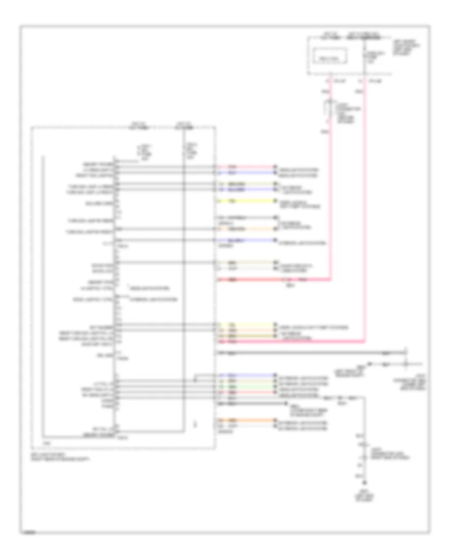
Backup Lamps Wiring Diagram for Hyundai Equus Ultimate 2014
 https://portal-diagnostov.com/license.html
Automotive Electricians Portal FZCO
Automotive Electricians Portal FZCO
https://portal-diagnostov.com/license.html
https://portal-diagnostov.com/license.html
Automotive Electricians Portal FZCO
Automotive Electricians Portal FZCOList of elements for Backup Lamps Wiring Diagram for Hyundai Equus Ultimate 2014:
- "c" pillar)
- Av & navigation head unit
- B/up
- Backup lamp
- Backup lamp relay
- C-can high
- C-can low
- Computer data lines system
- E/r fuse & relay box (left side of engine compt)
- E/r junction box (right rear of engine compt)
- E/r-ctb
- E/r-e2b
- Ef31
- Electrochromic mirror
- Fr11
- Gc201 (left rear of engine compt)
- Ge03 (left front of engine compt)
- Gf03 (left
- Gf09 (behind right
- Gnd
- Hot at all times
- Hot w/ pdm (ig1) relay energized
- Joint connector je02 (under left end of dash)
- Joint connector jf02 (base of left
- Joint connector jf03 (left kick panel)
- Lamp fuse 10a
- Left rear combination lamp
- M03-a
- Mf11
- On/start in
- Pnk
- Rear seat)
- Right rear combination lamp
- Sig 1
- Sig 2
- Sig 3
- Sig 4
- Tcm (transmission control module) (left rear of engine compt)
- Tcu fuse 15a
- Transmission range switch (left side of transmission)
Exterior Lamps Wiring Diagram (1 of 3) for Hyundai Equus Ultimate 2014
 https://portal-diagnostov.com/license.html
Automotive Electricians Portal FZCO
Automotive Electricians Portal FZCO
https://portal-diagnostov.com/license.html
https://portal-diagnostov.com/license.html
Automotive Electricians Portal FZCO
Automotive Electricians Portal FZCOList of elements for Exterior Lamps Wiring Diagram (1 of 3) for Hyundai Equus Ultimate 2014:
- 1.5v/1.275v reg
- 1.8v reg
- 3.3v reg
- 5v reg
- 7 inch
- B-can
- Brk lamp sw
- Brk pedal sw
- C-can transceiver
- C200-k
- Cluster fuse 10a
- Computer data lines system
- Ec21
- Ecm (left rear of engine compt)
- Ee31
- Ef11
- Ef31
- Em31
- Esc control module (left front of engine compt)
- Esc unit
- Ess sig
- Full
- Gm01 (left end of dash)
- Gm06 (left end of dash)
- Gnd
- Hac ctrl
- Hac sig
- Haz sw
- Haz sym
- Hazard fuse 10a
- Hot at all times
- Hot w/ pdm (ig1) relay energized
- I/p-lhc
- I/p-lhe
- I/p-lhf
- I/p-lhg
- Instrument cluster (7 inch tft lcd)
- Instrument cluster (full tft lcd)
- Ips control module
- Joint connector je01 (engine room fuse & relay box)
- Joint connector je02 (under left end of dash)
- Joint connector jf12 (base of right "c" pillar)
- Joint connector jm05 (center of dash)
- Left smart junction box (left end of dash)
- Left turn ind
- M30-b
- Memory pwr
- Micom
- Module 3 fuse 10a
- Module 4 fuse 10a
- Pnk
- Premium
- Red
- Right turn ind
- Rsm
- Smart key control module (under left side of dash)
- Standard
- Stop lamp fuse 10a
- Stop lamp switch (top of brake pedal assembly)
- Stop signal electronic module (left side of dash)
- Stp lmp
- Stp lmp sig
- Stp lmp sw
- Tft lcd
- Tft lcd driver
Exterior Lamps Wiring Diagram (2 of 3) for Hyundai Equus Ultimate 2014
 https://portal-diagnostov.com/license.html
Automotive Electricians Portal FZCO
Automotive Electricians Portal FZCO
https://portal-diagnostov.com/license.html
https://portal-diagnostov.com/license.html
Automotive Electricians Portal FZCO
Automotive Electricians Portal FZCOList of elements for Exterior Lamps Wiring Diagram (2 of 3) for Hyundai Equus Ultimate 2014:
- (under center console) srs control module
- A/bag fuse 15a
- Auto
- Bcm (under left side of dash)
- Center fascia switch
- Computer data lines system
- E/r fuse & relay box (left side of engine compt)
- Fr02
- Gf10 (behind left rear seat)
- Gm01 (left end of dash)
- Hot at all times
- Hot w/ pdm (ig1) relay energized
- I/p-lhf
- Ign1
- Interior lights system
- Joint connector jm03 (right end of dash)
- Joint connector jr11 (center of trunk lid)
- Left
- Left i/p junction box
- License lamp
- Light switch
- M/f sw ecu
- Multi-function switch
- Nca
- Off
- Pnk
- Red
- Right
- Sbr ind
- Sbr ind m32-b
- Stop lamp fuse 15a
- Telltale lamp
- Telltale lamp m53
- Trunk lid handle switch
- Trunk lid handle switch & license lamp
- Trunk, tailgate, fuel doors system
- Turn signal lamp switch
Exterior Lamps Wiring Diagram (3 of 3) for Hyundai Equus Ultimate 2014
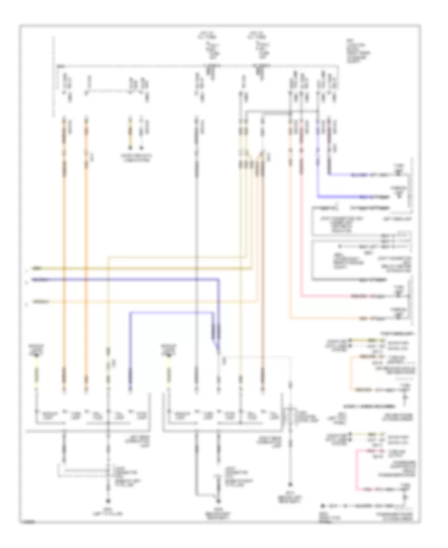 https://portal-diagnostov.com/license.html
Automotive Electricians Portal FZCO
Automotive Electricians Portal FZCO
https://portal-diagnostov.com/license.html
https://portal-diagnostov.com/license.html
Automotive Electricians Portal FZCO
Automotive Electricians Portal FZCOList of elements for Exterior Lamps Wiring Diagram (3 of 3) for Hyundai Equus Ultimate 2014:
- B-can high
- B-can low
- B-can low fam-b
- Backup lamp
- Backup lamps circuit
- Computer data lines system
- D51-b
- D51-c
- D61-b
- D61-c
- Driver door module (driver's door)
- Driver power outside mirror
- E/r junction block (right rear
- E/r-e1a
- E/r-e1b
- E/r-e2a
- Ee21
- Ef11
- Ef21
- Fam
- Fam 1 (b+) fuse 40a
- Fam 2 (b+) fuse 40a
- Fam-a
- Fam-a mem power
- Fam-b
- Fam-c
- Fam-c mem power
- Ff01
- Ge04 (lower right rear of engine compt)
- Gf01 (left kick panel)
- Gf03 (left "c" pillar)
- Gf05 (right kick panel)
- Gf09 (behind right rear seat)
- Gf10 (behind left rear seat)
- High mounted stop lamp
- Hot at all times
- Joint connector je12 (under left center of radiator)
- Joint connector je13 (below center of radiator)
- Joint connector jf02 (base of left "c" pillar)
- Joint connector jf12 (base of right "c" pillar)
- Lamp
- Left headlamp
- Left rear combination lamp
- Lr fail
- Lr turn sig lp fam-a
- Nca
- Of engine compt)
- Outside mirror
- Parking
- Passenger door module (front passenger's door)
- Passenger power
- Pnk
- Right headlamp
- Right rear combination lamp
- Right tail lamp fam-c
- Rr fail
- Rr turn sig lp fam-a
- Sig lp lf turn
- Sig lp rf turn
- Stop lamp
- Tail lamp
- Tail lamp left
- Tell tale
- Turn
- Turn lamp
- Turn sig output
GROUND DISTRIBUTION
Ground Distribution Wiring Diagram (1 of 7) for Hyundai Equus Ultimate 2014
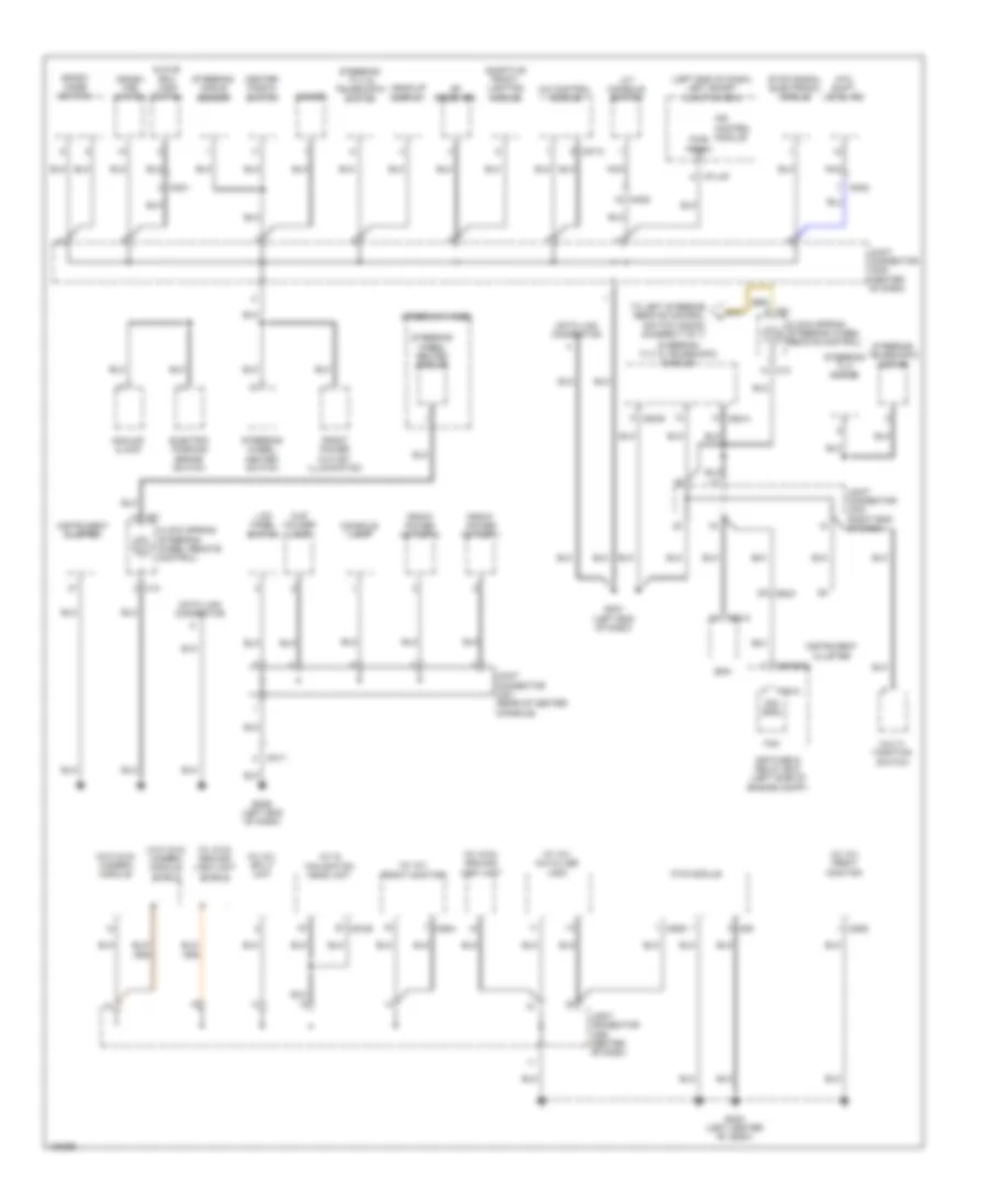 https://portal-diagnostov.com/license.html
Automotive Electricians Portal FZCO
Automotive Electricians Portal FZCO
https://portal-diagnostov.com/license.html
https://portal-diagnostov.com/license.html
Automotive Electricians Portal FZCO
Automotive Electricians Portal FZCOList of elements for Ground Distribution Wiring Diagram (1 of 7) for Hyundai Equus Ultimate 2014:
- (left end of dash) left smart junction box
- (w/ av) aux & usb jack
- (w/ av) front monitor
- (w/ av) split unit
- (w/ avm) around view unit
- (w/ avm) around view unit shield
- (w/o avm) camera module
- (w/o avm) camera module shield
- A/c control module
- A/t console switch
- A/v & navigation head unit
- Adaptive front lighting module
- Analog clock
- Atm shift level ind
- Bcm
- Center fascia switch
- Clock spring (steering wheel remote control)
- Console lamp
- Crash pad switch
- Cup holder lamp
- Data link connector
- E/r fuse & relay box (left side of engine compt)
- E/r-e1b
- Electric parking brake switch
- Em21
- Fam
- Fam-c
- Front power outlet 1
- Front power outlet 2
- Front power outlet illumination
- Glove box lamp switch
- Gm01 (left end of dash)
- Gm03 (left center of dash)
- Gm06 (left end of dash)
- Head-up display
- I/p-lhf
- Instrument cluster
- Ionizer
- Ips control module
- Joint connector jm03 (right end of dash)
- Joint connector jm05 (center of dash)
- Joint connector jm21 (rear of center console)
- Lcd panel switch
- M03-b
- M06
- M06g
- M07-c
- M13
- M25g
- M25h
- M32-a
- M52-a
- M52-b
- M91
- Mm01
- Mm02
- Mm11
- Mts module
- Multi- function switch
- Nca
- Pwr (gnd)
- Rf receiver
- Sig (gnd)
- Sport mode switch
- Steering angle sensor
- Steering telescopic motor
- Steering tilt & telescopic module
- Steering tilt & telescopic switch
- Steering tilt motor
- Steering wheel
- Steering wheel heated module
- Steering wheel heated switch
- Stop signal electronic module
- To left steering remote control switch (down) (diagram 7 of 7)
Ground Distribution Wiring Diagram (2 of 7) for Hyundai Equus Ultimate 2014
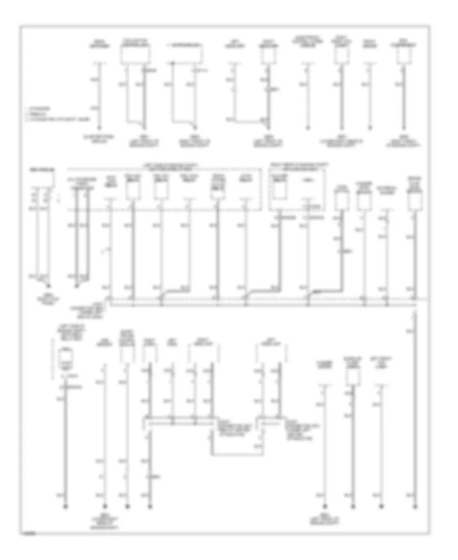 https://portal-diagnostov.com/license.html
Automotive Electricians Portal FZCO
Automotive Electricians Portal FZCO
https://portal-diagnostov.com/license.html
https://portal-diagnostov.com/license.html
Automotive Electricians Portal FZCO
Automotive Electricians Portal FZCOList of elements for Ground Distribution Wiring Diagram (2 of 7) for Hyundai Equus Ultimate 2014:
- (left side of engine compt) e/r fuse & relay box
- (right rear of engine compt) e/r junction box
- Aqs sensor
- B/up lamp relay
- Blower relay
- Brake fluid level sensor
- Burglar alarm horn
- C/fan relay
- Cooling fan controller
- E/r-e1b
- E/r-e2b
- E05-b
- E11-m
- Ecs compressor
- Ee21
- Ee31
- Ehps module
- Electronic control wiper module
- Esc module
- External buzzer
- Fam
- Fam-b
- Fam-c
- Front deicer
- Front power outlet relay
- Ge01 (left front of engine compt)
- Ge02 (right kick panel)
- Ge03 (left front of engine compt)
- Ge04 (lower right rear of engine compt)
- Ge05 (right front of engine compt)
- Ge06 (left front of engine compt)
- Ge07 (lower right rear of engine compt)
- Ge08 (right front of engine compt)
- Hood switch
- Joint connector je02 (under left end of dash)
- Joint connector je12 (under left center of radiator)
- Joint connector je13 (below center of radiator)
- Left front fog lamp
- Left headlamp
- Left horn
- Multipurpose check connector
- Nca
- Pdm (acc) relay
- Pdm (ig1) relay
- Pdm (ig2) relay
- Premium
- Pwr (gnd)
- Quarter panel ground
- Rear defogger
- Right front fog lamp
- Right headlamp
- Right horn
- Smart cruise control module
- Standard
- W/o electric atm shift lever
- Washer level sensor
- Washer motor
Ground Distribution Wiring Diagram (3 of 7) for Hyundai Equus Ultimate 2014
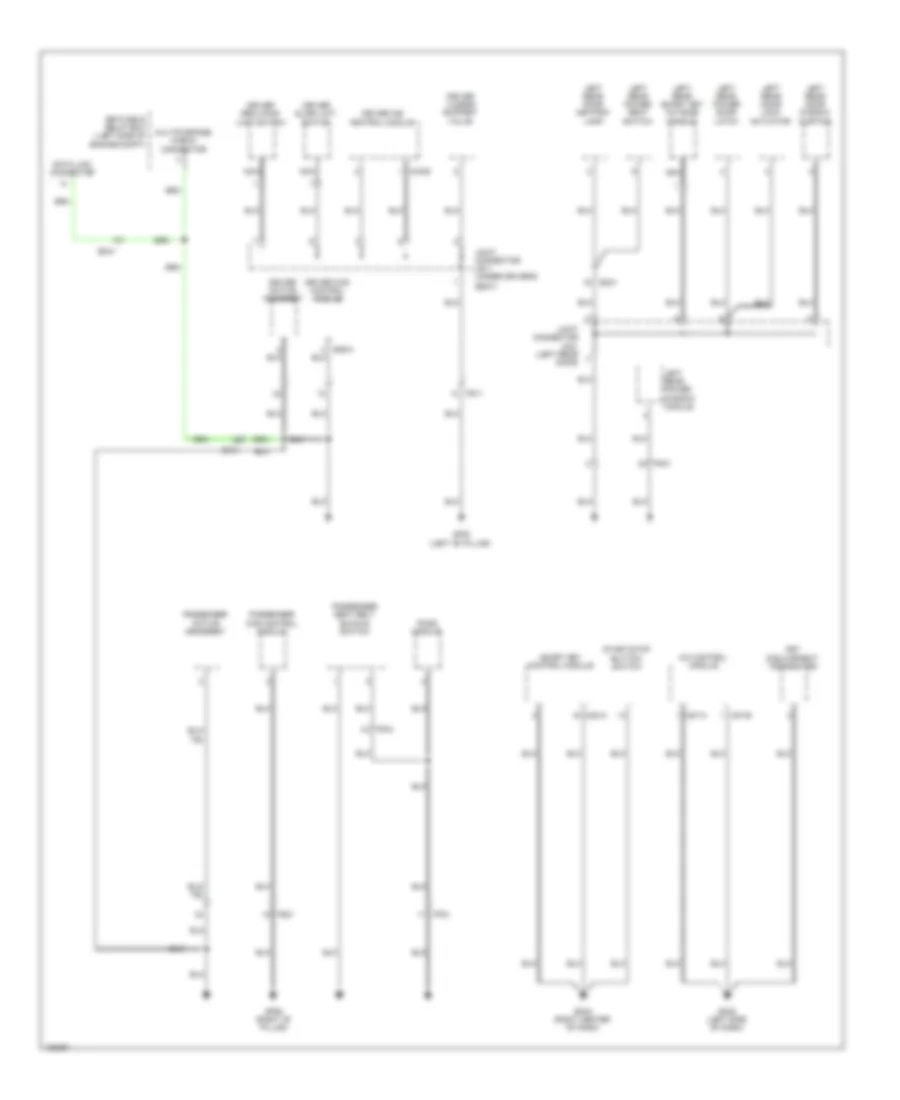 https://portal-diagnostov.com/license.html
Automotive Electricians Portal FZCO
Automotive Electricians Portal FZCO
https://portal-diagnostov.com/license.html
https://portal-diagnostov.com/license.html
Automotive Electricians Portal FZCO
Automotive Electricians Portal FZCOList of elements for Ground Distribution Wiring Diagram (3 of 7) for Hyundai Equus Ultimate 2014:
- A/c control module
- Data link connector
- Dd31
- Driver active headrest
- Driver ccs control module
- Driver ims control module
- Driver lumbar support valve
- Driver reclining limit switch
- Driver slide limit switch
- E/r fuse & relay box (left side of engine compt)
- Ef31
- Em41
- Fd31
- Fet (field effect transistor)
- Ff04
- Fs11
- Fs21
- Gf02 (left "b" pillar)
- Gf06 (right "b" pillar)
- Gm02 (left side of dash)
- Gm04 (right center of dash)
- Joint connector jd31 (left rear door)
- Joint connector js11 (under driver's
- Left rear door ashtray lamp
- Left rear door lock actuator
- Left rear door window curtain
- Left rear power door latch
- Left rear power seat switch
- Left rear power window module
- Left rear smart key outside handle
- M07-a
- M07-b
- M30-a
- Multipurpose check connector
- Nca
- Passenger active headrest
- Passenger ccs control module
- Passenger seat belt buckle switch
- Pods module
- S06-a
- S16-b
- Seat)
- Smart key control module
- Start/stop button switch
Ground Distribution Wiring Diagram (4 of 7) for Hyundai Equus Ultimate 2014
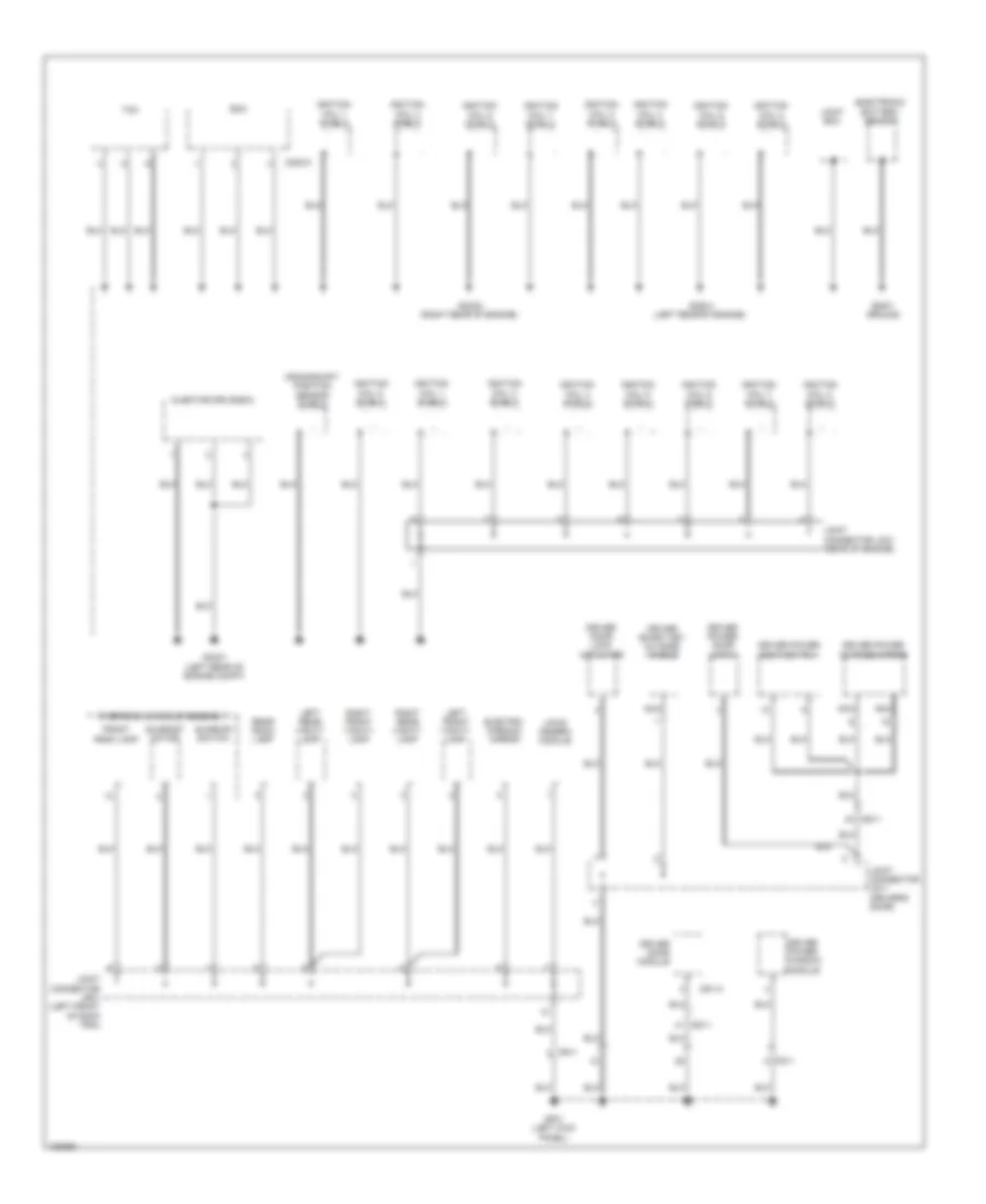 https://portal-diagnostov.com/license.html
Automotive Electricians Portal FZCO
Automotive Electricians Portal FZCO
https://portal-diagnostov.com/license.html
https://portal-diagnostov.com/license.html
Automotive Electricians Portal FZCO
Automotive Electricians Portal FZCOList of elements for Ground Distribution Wiring Diagram (4 of 7) for Hyundai Equus Ultimate 2014:
- Body ground
- C200-k
- Crankshaft position sensor shield
- D51-a
- Dd11
- Driver door lock actuator
- Driver door module
- Driver power door latch
- Driver power outside mirror
- Driver power seat switch
- Driver power window module
- Driver smart key outside handle
- Ecm
- Electro- chromic mirror
- Electronic battery sensor
- Fd11
- Fr11
- Front room lamp
- Gc201 (left rear of engine compt)
- Gc202 (right rear of engine)
- Gc203 (left rear of engine)
- Gf01 (left kick panel)
- Ignition coil 1 shield
- Ignition coil 2 shield
- Ignition coil 3 shield
- Ignition coil 4 shield
- Ignition coil 5 shield
- Ignition coil 6 shield
- Ignition coil 7 shield
- Ignition coil 8 shield
- Injector drive box
- Joint box
- Joint connector jc21 (rear of engine)
- Joint connector jd11 (driver's door)
- Joint connector jr01 (left front of roof trim)
- Ldws camera module
- Left front vanity lamp
- Left rear vanity lamp
- Nca
- Overhead console assembly
- Rear room lamp
- Right front vanity lamp
- Right rear vanity lamp
- Sunroof motor
- Sunroof switch
- Tcm
Ground Distribution Wiring Diagram (5 of 7) for Hyundai Equus Ultimate 2014
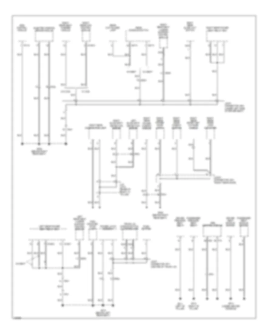 https://portal-diagnostov.com/license.html
Automotive Electricians Portal FZCO
Automotive Electricians Portal FZCO
https://portal-diagnostov.com/license.html
https://portal-diagnostov.com/license.html
Automotive Electricians Portal FZCO
Automotive Electricians Portal FZCOList of elements for Ground Distribution Wiring Diagram (5 of 7) for Hyundai Equus Ultimate 2014:
- 5:5 seat
- 6:4 seat
- Driver pre-safe seat belt
- Driver seat buckle switch
- Ecs control module
- Electric parking brake module
- F01-g
- F10
- Fd41
- Ff01
- Ff02
- Fr02
- Fr31
- Fs31
- Fs41
- Gf08 (behind right rear seat)
- Gf09 (behind right rear seat)
- Gf10 (behind left rear seat)
- Gf11 (left "b" pillar)
- Gf12 (right "b" pillar)
- Gf13 (under center console)
- High- mounted stop lamp
- J/c jf12 (base of
- Joint connector jd41 (right rear door)
- Joint connector jr11 (center of trunk lid)
- Joint connector js31 (under left side of driver seat)
- Left blind spot detection radar
- Left rear power seat relay box
- Left rear seat lumbar support control module
- M53
- Mf01
- Nca
- Passenger pre-safe seat belt
- Passenger seat buckle switch
- Power latch assembly
- Push button
- Rear console switch
- Rear cup holder lamp
- Right "c" pillar)
- Right blind spot detection radar
- Right rear ccs control module
- Right rear combination lamp
- Right rear door lock actuator
- Right rear door window curtain
- Right rear power door latch
- Right rear power seat relay box
- Right rear power window module
- Right rear seat lumbar support control module
- Right rear seat warmer module
- Right rear slide limit switch
- Right rear smart key outside handle
- S126-1
- S126-2
- S146-a
- S27-a
- S37-a
- Srs control module
- Ss32
- Ss41
- Ss42
- Trunk lid handle switch & license lamp
- W/ ccs
- W/o ccs
Ground Distribution Wiring Diagram (6 of 7) for Hyundai Equus Ultimate 2014
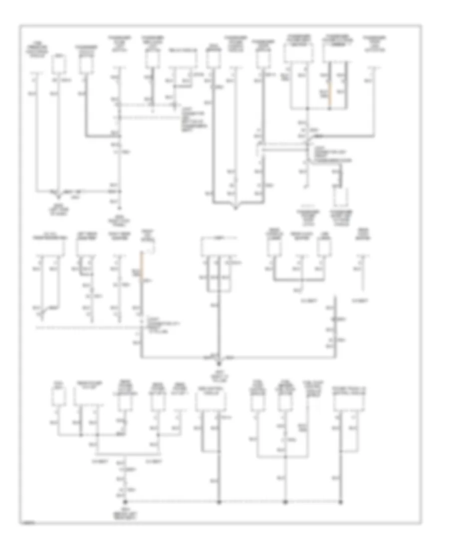 https://portal-diagnostov.com/license.html
Automotive Electricians Portal FZCO
Automotive Electricians Portal FZCO
https://portal-diagnostov.com/license.html
https://portal-diagnostov.com/license.html
Automotive Electricians Portal FZCO
Automotive Electricians Portal FZCOList of elements for Ground Distribution Wiring Diagram (6 of 7) for Hyundai Equus Ultimate 2014:
- (w/ av) front dis switch
- 5:5 seat
- 6:4 seat
- Amp
- Bcm
- Cool box
- D61-a
- Dd21
- Ecs control module
- F01-a
- F03-a
- Fd21
- Ff03
- Fr11
- Fr21
- Front mic shield
- Fs11
- Fs21
- Fs31
- Fuel pump control module
- Fuel pump control module shield
- Fuel sender fuel pump motor
- Gf04 (behind left rear seat)
- Gf05 (right kick panel)
- Gf07 (right "c" pillar)
- Gm05 (left side of dash)
- Joint connector jd21 (front passenger's door)
- Joint connector jf11 (right "c" pillar)
- Joint connector js21 (bottom of passenger's seat)
- Left rear monitor
- M32-a
- Mf21
- Nca
- Passenger door lock actuator
- Passenger door module
- Passenger power door latch
- Passenger power outside mirror
- Passenger power seat switch
- Passenger power window module
- Passenger reclining limit switch
- Passenger slide limit switch
- Passenger smart key outside handle
- Passenger walk in switch
- Power trunk lid control module
- Rain sensor
- Rear audio switch
- Rear console lamp
- Rear power outlet
- Rear power outlet 1
- Rear power outlet 2
- Rear power outlet illumination
- Relax module
- Right rear monitor
- S70-b
- Ss31
- Tire pressure monitoring module
- Usb jack
Ground Distribution Wiring Diagram (7 of 7) for Hyundai Equus Ultimate 2014
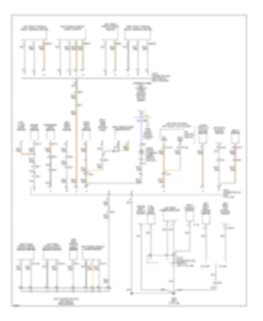 https://portal-diagnostov.com/license.html
Automotive Electricians Portal FZCO
Automotive Electricians Portal FZCO
https://portal-diagnostov.com/license.html
https://portal-diagnostov.com/license.html
Automotive Electricians Portal FZCO
Automotive Electricians Portal FZCOList of elements for Ground Distribution Wiring Diagram (7 of 7) for Hyundai Equus Ultimate 2014:
- (left end of dash) left smart junction box
- B/up (gnd)
- Clock spring (steering wheel remote control)
- D51-c
- D61-c
- Dd11
- Dd21
- Dd31
- Dd41
- Driver door module
- Driver ims control module
- Driver seat buckle switch
- E92-cl
- E92-cr
- E92-l
- E92-r
- Ee41
- Ef11
- F11-b
- Fd11
- Fd21
- Fd31
- Fd41
- Fr31
- From clock spring (diagram (1 of 7)
- Front console switch
- Fs11
- Fs21
- Fs31
- Fuel filler door motor
- Fuel filter door switch
- Gf03 (left "c" pillar)
- I/p-lhf
- I/p-lhg
- Ips control module
- Joint connector je21 (left end of front bumper)
- Joint connector jf01 (left "c" pillar)
- Joint connector jf02 (base of left "c" pillar)
- Joint connector jr22 (left side of rear bumper)
- Left front parking assist sensor
- Left front parking assist sensor (center)
- Left rear ccs control module
- Left rear combination lamp
- Left rear door module
- Left rear parking assist sensor
- Left rear parking assist sensor (center)
- Left rear seat warmer module
- Left steering wheel remote control switch (down)
- M13
- M91
- Mcu (gnd)
- Mf11
- Passenger door module
- Power trunk lid control module
- R31-cl
- R31-cr
- R31-l
- R31-r
- Relax module
- Right front parking assist sensor
- Right front parking assist sensor (center)
- Right rear door ashtray lamp
- Right rear door module
- Right rear parking assist sensor
- Right rear parking assist sensor (center)
- Right rear power seat switch
- S106-a
- S16-d
- S70-d
- Steering wheel
- W/ ccs
- W/o ccs
HEADLIGHTS
Adaptive Front Lighting Wiring Diagram for Hyundai Equus Ultimate 2014
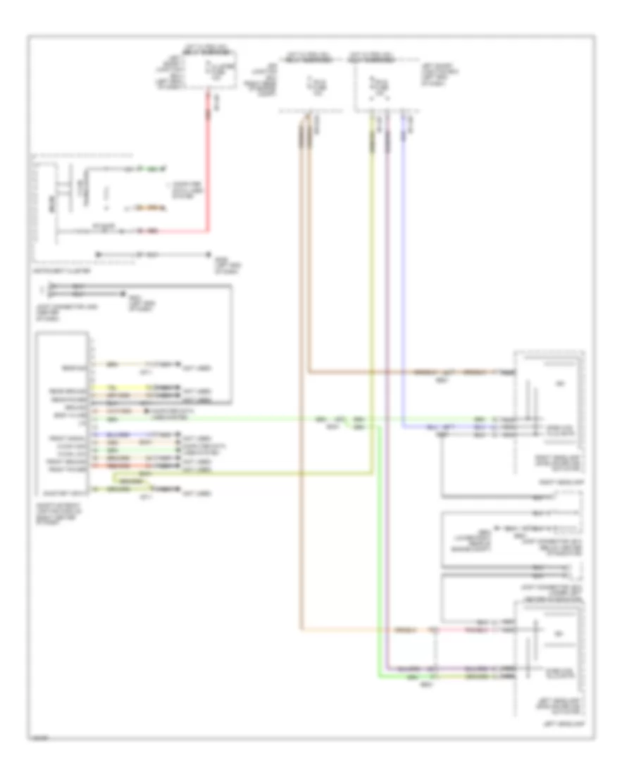 https://portal-diagnostov.com/license.html
Automotive Electricians Portal FZCO
Automotive Electricians Portal FZCO
https://portal-diagnostov.com/license.html
https://portal-diagnostov.com/license.html
Automotive Electricians Portal FZCO
Automotive Electricians Portal FZCOList of elements for Adaptive Front Lighting Wiring Diagram for Hyundai Equus Ultimate 2014:
- (not used)
- (right rear
- Adaptive front lighting module (right center of dash)
- Afls fuse 10a
- Afls ind
- Body k-line
- C-can high
- C-can low
- Cluster fuse 10a
- Compt)
- Computer data lines system
- E/r junction box
- E/r-e2a
- Ee21
- Em21
- Em41
- Front ground
- Front power
- Front signal
- Ge04 (lower right rear of engine compt)
- Gm01 (left end of dash)
- Gm06 (left end of dash)
- Ground
- Hot w/ pdm (ig1) relay energized
- I/p-lhe
- I/p-lhf
- Instrument cluster
- Ism
- Joint connector je12 (under left center of radiator)
- Joint connector je13 (below center of radiator)
- Joint connector jm05 (center of dash)
- Left headlamp
- Left headlamp leveling device actuator
- Left smart junction box (left end of dash)
- Lin
- Mf11
- Micom
- Nca
- Of engine
- On/start input
- Rear ground
- Rear power
- Rear sig
- Red
- Right headlamp
- Right headlamp leveling device actuator
- Step mtr hlld actr
- Transceiver c-can
Headlamps Wiring Diagram for Hyundai Equus Ultimate 2014
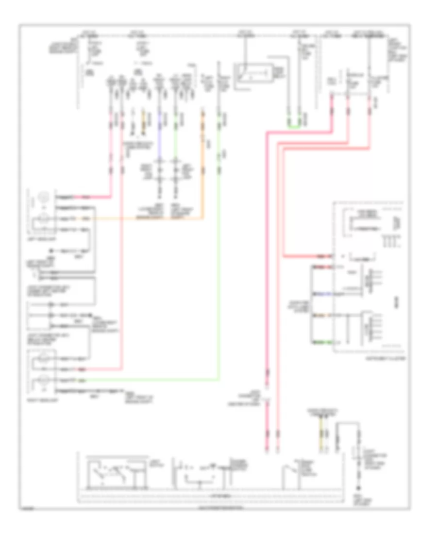 https://portal-diagnostov.com/license.html
Automotive Electricians Portal FZCO
Automotive Electricians Portal FZCO
https://portal-diagnostov.com/license.html
https://portal-diagnostov.com/license.html
Automotive Electricians Portal FZCO
Automotive Electricians Portal FZCOList of elements for Headlamps Wiring Diagram for Hyundai Equus Ultimate 2014:
- (left front of engine compt)
- (lower right rear of engine compt)
- 3.3v reg
- Auto
- B- can high
- B- can low
- Cluster fuse 10a
- Computer data lines system
- Cruise (b+) fuse 10a
- Dim
- Dimmer/ passing switch
- Drive tft lcd
- E/r junction box (right rear of engine compt)
- E/r-e1a
- E/r-e1b
- E/r-e2a
- E/r-e2b
- Ee21
- Ee31
- Fam
- Fam 1 (b+) fuse 40a
- Fam 2 (b+) fuse 40a
- Fam-a
- Fam-b
- Fam-c
- Front fog
- Front fog lamp switch
- Ge03 (left front of engine compt)
- Ge04
- Ge06
- Ge06 (left front of engine compt)
- Ge07 (lower right rear of engine compt)
- Gm01 (left end of dash)
- Head lamp relay
- Head lamp relay ctrl
- High beam/ low beam
- Hot at all times
- Hot w/ pdm (ig1) relay energized
- I/p-lhf
- Instrument cluster
- Ips 3 (1ch)
- Joint connector je12 (under left center of radiator)
- Joint connector je13 (below center of radiator)
- Joint connector jm01 (center of dash)
- Joint connector jm03 (right end of dash)
- Left front fog lamp
- Left h/lp fuse 15a
- Left headlamp
- Left smart junction box (left end of dash)
- Lh front fog lamp
- Lh head lamp hi
- Light switch
- M/f sw ecu
- Mem pwr
- Micom
- Module fuse 10a
- Multi-function switch
- Nca
- Off
- Pass
- Pnk
- Red
- Rh front fog lamp
- Rh head lamp hi
- Right front fog lamp
- Right h/lp fuse 15a
- Right headlamp
- Tft lcd
- Transceiver c-can
- Transceiver m-can
HORN
Horn Wiring Diagram for Hyundai Equus Ultimate 2014
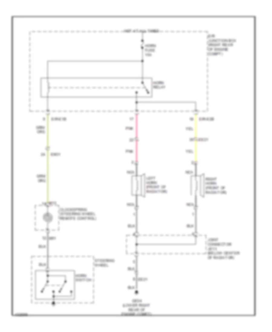 https://portal-diagnostov.com/license.html
Automotive Electricians Portal FZCO
Automotive Electricians Portal FZCO
https://portal-diagnostov.com/license.html
https://portal-diagnostov.com/license.html
Automotive Electricians Portal FZCO
Automotive Electricians Portal FZCOList of elements for Horn Wiring Diagram for Hyundai Equus Ultimate 2014:
- Clockspring (steering wheel remote control)
- E/r junction box (right rear of engine compt)
- E/r-e1b
- E/r-e2b
- Ee21
- Em31
- Ge04 (lower right rear of engine compt)
- Horn fuse 15a
- Horn relay
- Horn switch
- Hot at all times
- Joint connector je13 (below center of radiator)
- Left horn (front of radiator)
- M13
- M91
- Nca
- Pnk
- Right horn (front of radiator)
- Steering wheel
INSTRUMENT CLUSTER
Head-Up Display Wiring Diagram for Hyundai Equus Ultimate 2014
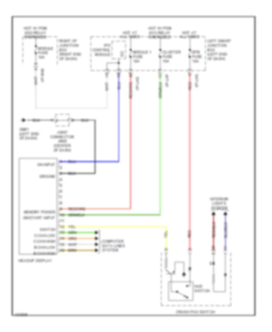 https://portal-diagnostov.com/license.html
Automotive Electricians Portal FZCO
Automotive Electricians Portal FZCO
https://portal-diagnostov.com/license.html
https://portal-diagnostov.com/license.html
Automotive Electricians Portal FZCO
Automotive Electricians Portal FZCOList of elements for Head-Up Display Wiring Diagram for Hyundai Equus Ultimate 2014:
- B-can high
- B-can low
- C-can high
- C-can low
- Cluster fuse 10a
- Computer data lines system
- Crash pad switch
- Epb fuse 10a
- Gm01 (left end of dash)
- Ground
- Headup display
- Hot at all times
- Hot w/ pdm (ig1) relay energized
- Hot w/ pdm (ig2) relay energized
- Hud switch
- I/p-lhf
- I/p-lhg
- I/p-rhd
- Ig2
- Interior lights system
- Ips control module
- Joint connector jm05 (center of dash)
- Left smart junction box (left end of dash)
- Memory power
- Module 1 fuse 10a
- Module fuse 10a
- On input
- On/start input
- Red
- Right i/p junction box (right end of dash)
- Switch
Instrument Cluster Wiring Diagram, 7 Inch TFT LCD Type (1 of 3) for Hyundai Equus Ultimate 2014
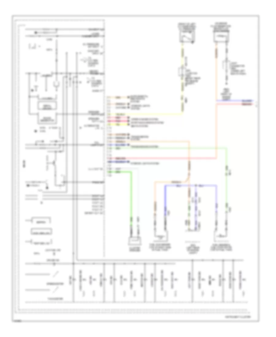 https://portal-diagnostov.com/license.html
Automotive Electricians Portal FZCO
Automotive Electricians Portal FZCO
https://portal-diagnostov.com/license.html
https://portal-diagnostov.com/license.html
Automotive Electricians Portal FZCO
Automotive Electricians Portal FZCOList of elements for Instrument Cluster Wiring Diagram, 7 Inch TFT LCD Type (1 of 3) for Hyundai Equus Ultimate 2014:
- (front of left cylinder bank) oil pressure switch
- (on brake fluid reservoir) brake fluid level sensor
- 3.3v reg
- 5v reg
- Abs ind
- Afls ind
- Alternator l in
- Break ind
- C200-a
- Charge ind
- Check engine ind
- Cluster speaker
- Cruise ind
- D out
- Detent out
- Door open ind
- E/r -ctb
- E/r -e2b
- E/r junction box (right rear of engine compt)
- Ec21
- Ecm (left rear of engine compt)
- Eeprom
- Ef11
- Ef31
- Em21
- Epb ind
- Ff03
- Fuel seg lcd
- Fuel sender & fuel pump motor (top of fuel tank)
- Fuel sub sender (top of right side of fuel tank)
- Ge03 (left front of engine compt)
- I/f
- Ill (-) out
- Immo ind
- Instrument cluster
- Interior lights system
- Joint connector je02 (under left end of dash)
- Left turn ind
- Low fuel ind
- Lower washer input
- Master ind
- Memory power
- Mf11
- Micom
- N out
- Nca
- Oil pressure ind
- Oil pressure sw input
- On input
- On/start input
- P out
- P-gnd
- Pnk
- R out
- Red
- Right turn ind
- S out
- S-gnd
- Seat belt ind
- Seats system
- Serial memory
- Set ind
- Sound generator
- Speaker out (+)
- Speaker out (-)
- Speedometer
- Starting/charging system
- Tachometer
- Tail lamp in
- Temp seg lcd
- To 3.3v reg (diagram 3 of 3)
- Tpms tread ind
- Transmissions system
- Trunk open ind
- Vsm off ind
- Wiper/washer system
Instrument Cluster Wiring Diagram, 7 Inch TFT LCD Type (2 of 3) for Hyundai Equus Ultimate 2014
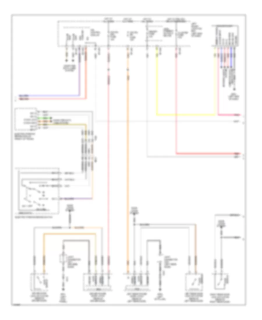 https://portal-diagnostov.com/license.html
Automotive Electricians Portal FZCO
Automotive Electricians Portal FZCO
https://portal-diagnostov.com/license.html
https://portal-diagnostov.com/license.html
Automotive Electricians Portal FZCO
Automotive Electricians Portal FZCOList of elements for Instrument Cluster Wiring Diagram, 7 Inch TFT LCD Type (2 of 3) for Hyundai Equus Ultimate 2014:
- Acc/on input
- Ajar switch
- Analog clock
- C-can high
- C-can low
- Cluster fuse 10a
- Computer data lines system
- Door locks system
- Driver door lock actuator (rear of driver door)
- Driver power door latch (rear of driver door)
- Ecu
- Electric parking brake module (front of trunk)
- Electric parking brake switch
- Epb switch
- Fd11
- Fd31
- Ff02
- Fluid sw brk
- Gf01 (left kick panel)
- Gf02 (left "b" pillar)
- Gm01 (left end of dash)
- Ground
- Ground signal
- High b-can
- Hot at all times
- Hot w/ pdm (ig1) relay energized
- I/p-lhc
- I/p-lhe
- I/p-lhf
- I/p-lhg
- Ig2
- Ill (+)
- Ill (-)
- Interior lights system
- Ips control module
- Joint connector jd11 (driver's door)
- Joint connector jd31 (left rear door)
- Leak current autocut device
- Left rear door lock actuator (rear of left rear door)
- Left rear power door latch (rear of left rear door)
- Left smart junction box (left end of dash)
- Lines system computer data
- Low b-can
- M-can high
- M-can low
- Memory fuse 10a
- Memory power
- Mf21
- O/s hdl drv fuse 15a
- O/s hdl rr fuse 15a
- Pnk
- Red
- Right rear door lock actuator (rear of right rear door)
- Sw 1
- Sw 1 app
- Sw 2
- Sw 2 rel
- Sw 3
- Sw 4
- Switch ajar
Instrument Cluster Wiring Diagram, 7 Inch TFT LCD Type (3 of 3) for Hyundai Equus Ultimate 2014
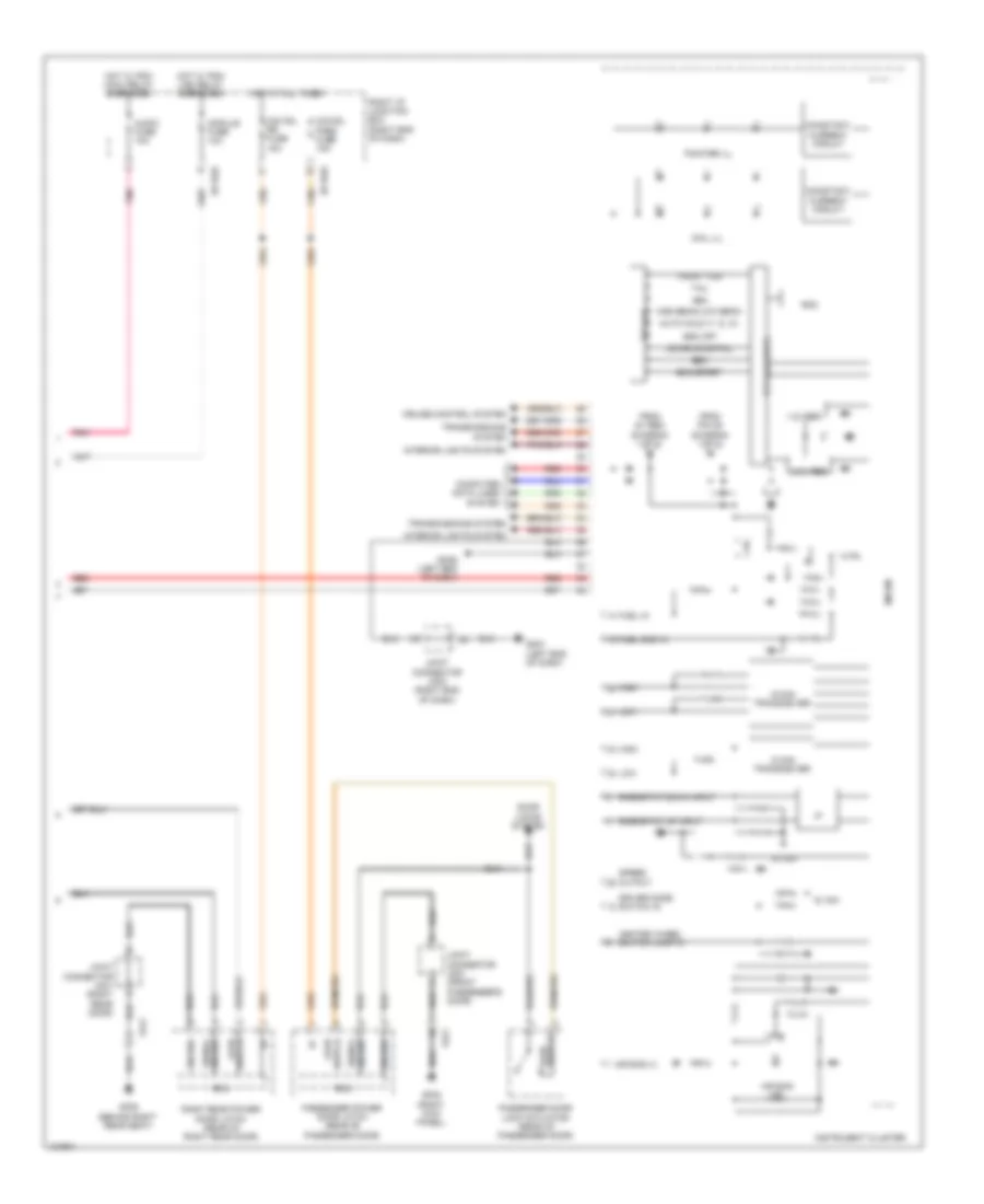 https://portal-diagnostov.com/license.html
Automotive Electricians Portal FZCO
Automotive Electricians Portal FZCO
https://portal-diagnostov.com/license.html
https://portal-diagnostov.com/license.html
Automotive Electricians Portal FZCO
Automotive Electricians Portal FZCOList of elements for Instrument Cluster Wiring Diagram, 7 Inch TFT LCD Type (3 of 3) for Hyundai Equus Ultimate 2014:
- 1.2v reg
- 3.3v reg
- 5v sw
- Air bag (+)
- Air bag ind
- Audio fuse 10a
- Auto hold (y, g, w)
- C-can transceiver
- Computer data lines system
- Constant current circuit
- Cruise control system
- Dail ill
- Door locks system
- Driver mode switch in
- Eco/sport
- Ecu
- Esc
- Esc off
- Fd21
- Fd41
- From 5v reg (diagram 1 of 3)
- From pin 39 (diagram 1 of 3)
- Front fog
- Fuel gnd in
- Fuel in
- Gf05 (right kick panel)
- Gf09 (behind right rear seat)
- Gm01 (left end of dash)
- Gm06 (left end of dash)
- Ground
- Ground signal
- Hba
- Heated wheel switch lamp in
- High
- High beam/low beam
- Hot at all times
- Hot w/ pdm (acc) relay energized
- Hot w/ pdm (ig2) relay energized
- I/f
- I/p-rhd
- I/p-rhe
- Instrument cluster
- Interior lights system
- Joint connector jd21 (front passenger's door)
- Joint connector jd41 (right rear door)
- Joint connector jm03 (right end of dash)
- Ldws/ldws fail
- Low
- M-can transceiver
- Micom
- Module fuse 10a
- O/s hdl pass fuse 15a
- O/s hdl rr fuse 15a
- Passenger door lock actuator (rear of passenger door)
- Passenger power door latch (rear of passenger door)
- Pnk
- Pointer ill
- Red
- Rheostat down input
- Rheostat up input
- Right i/p junction box (right end of dash)
- Right rear power door latch (rear of right rear door)
- Rom
- Speed output
- Switch ajar
- Tail
- Tft lcd
- Tft lcd drive
- Transmissions system
Instrument Cluster Wiring Diagram, Full TFT LCD Type (1 of 3) for Hyundai Equus Ultimate 2014
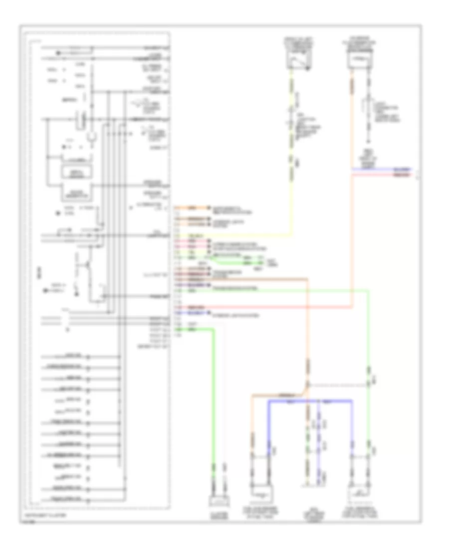 https://portal-diagnostov.com/license.html
Automotive Electricians Portal FZCO
Automotive Electricians Portal FZCO
https://portal-diagnostov.com/license.html
https://portal-diagnostov.com/license.html
Automotive Electricians Portal FZCO
Automotive Electricians Portal FZCOList of elements for Instrument Cluster Wiring Diagram, Full TFT LCD Type (1 of 3) for Hyundai Equus Ultimate 2014:
- (front of left cylinder bank) oil pressure switch
- (not used)
- (on brake fluid reservoir) brake fluid level sensor
- 3.3v reg
- 5v reg
- Abs ind
- Afls ind
- Alternator l in
- Break ind
- C200-a
- Charge ind
- Check engine ind
- Cluster speaker
- D out
- Detent out
- Door open ind
- E/r -ctb
- E/r -e2b
- E/r junction box (right rear of engine compt)
- Ec21
- Ecm (left rear of engine compt)
- Ee21
- Eeprom
- Ef11
- Ef31
- Em21
- Em41
- Epb ind
- Ff03
- Fuel sender & fuel pump motor (top of fuel tank)
- Fuel sub sender (top of right side of fuel tank)
- Ge03 (left front of engine compt)
- I/f
- Ill (-) out
- Immo ind
- Instrument cluster
- Interior lights system
- Joint connector je02 (under left end of dash)
- Led off input
- Lower washer input
- Master ind
- Memory power
- Mf11
- Micom
- N out
- Nca
- Oil press sw input
- Oil pressure ind
- On input
- On/start input
- P out
- P-gnd
- Pnk
- R out
- Red
- S out
- S-gnd
- Seat belt ind
- Seats system
- Serial memory
- Sound generator
- Speaker out (+)
- Speaker out (-)
- Starting/charging system
- Tail lamp in
- To 3.3v reg (diagram 3 of 3)
- Tpms tread ind
- Transmissions system
- Trunk open ind
- Vsm off ind
- Wiper/washer system
Instrument Cluster Wiring Diagram, Full TFT LCD Type (2 of 3) for Hyundai Equus Ultimate 2014
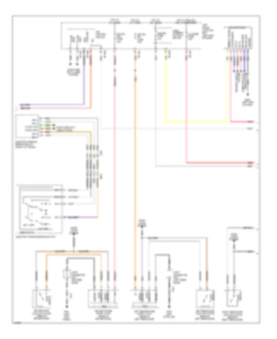 https://portal-diagnostov.com/license.html
Automotive Electricians Portal FZCO
Automotive Electricians Portal FZCO
https://portal-diagnostov.com/license.html
https://portal-diagnostov.com/license.html
Automotive Electricians Portal FZCO
Automotive Electricians Portal FZCOList of elements for Instrument Cluster Wiring Diagram, Full TFT LCD Type (2 of 3) for Hyundai Equus Ultimate 2014:
- Acc/on input
- Analog clock
- C-can high
- C-can low
- Cluster fuse 10a
- Computer data lines system
- Door locks system
- Driver door lock actuator (rear of driver door)
- Driver power door latch (rear of driver door)
- Ecu
- Electric parking brake module (front of trunk)
- Electric parking brake switch
- Epb switch
- Fd11
- Fd31
- Ff02
- Fluid sw brk
- Gf01 (left kick panel)
- Gf02 (left "b" pillar)
- Gm01 (left end of dash)
- Ground
- Ground signal
- High b-can
- Hot at all times
- Hot w/ pdm (ig1) relay energized
- I/p-lhc
- I/p-lhe
- I/p-lhf
- I/p-lhg
- Ig2
- Ill (+)
- Ill (-)
- Interior lights system
- Ips control module
- Joint connector jd11 (driver's door)
- Joint connector jd31 (left rear door)
- Leak current autocut device
- Left rear door lock actuator (rear of left rear door)
- Left rear power door latch (rear of left rear door)
- Left smart junction box (left end of dash)
- Lines system computer data
- Low b-can
- M-can high
- M-can low
- Memory fuse 10a
- Memory power
- Mf21
- O/s hdl drv fuse 15a
- O/s hdl rr fuse 15a
- Pnk
- Red
- Right rear door lock actuator (rear of right rear door)
- Sw 1
- Sw 1 app
- Sw 2
- Sw 2 rel
- Sw 3
- Sw 4
- Switch ajar
Instrument Cluster Wiring Diagram, Full TFT LCD Type (3 of 3) for Hyundai Equus Ultimate 2014
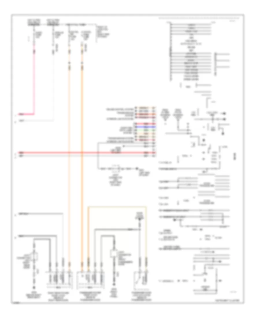 https://portal-diagnostov.com/license.html
Automotive Electricians Portal FZCO
Automotive Electricians Portal FZCO
https://portal-diagnostov.com/license.html
https://portal-diagnostov.com/license.html
Automotive Electricians Portal FZCO
Automotive Electricians Portal FZCOList of elements for Instrument Cluster Wiring Diagram, Full TFT LCD Type (3 of 3) for Hyundai Equus Ultimate 2014:
- 1.5v/1.275v reg
- 1.8v reg
- 3.3v reg
- 5v sw
- Air bag (+)
- Air bag ind
- Audio fuse 10a
- Auto hold (y, g, w)
- C-can transceiver
- Computer data lines system
- Cruise
- Cruise control system
- Door locks system
- Driver mode switch in
- Eco (w, g, r)
- Ecu
- Fd21
- Fd41
- From 5v reg (diagram 1 of 3)
- From pin 39 (diagram 1 of 3)
- Front fog
- Fuel gauge
- Fuel gnd in
- Fuel in
- Gdc (tft lcd driver)
- Gf05 (right kick panel)
- Gf09 (behind right rear seat)
- Gm01 (left end of dash)
- Gm06 (left end of dash)
- Ground
- Ground signal
- Hba
- Heated wheel switch lamp in
- High
- High beam
- High temp
- Hot at all times
- Hot w/ pdm (acc) relay energized
- Hot w/ pdm (ig2) relay energized
- I/p-rhd
- I/p-rhe
- Instrument cluster
- Interior lights system
- Joint connector jd21 (front passenger's door)
- Joint connector jd41 (right rear door)
- Joint connector jm03 (right end of dash)
- Ldws (g, w)
- Low
- Low fuel
- M-can transceiver
- Micom
- Module fuse 10a
- O/s hdl pass fuse 15a
- O/s hdl rr fuse 15a
- Passenger door lock actuator (rear of passenger door)
- Passenger power door latch (rear of passenger door)
- Pnk
- Red
- Rheostat down input
- Rheostat up input
- Right i/p junction box (right end of dash)
- Right rear power door latch (rear of right rear door)
- Rom
- Set
- Speed meter
- Speed output
- Sport
- Switch ajar
- Switch pawl
- Tacho meter
- Tail
- Temp gauge
- Tft lcd
- Transmissions system
- Turn l
- Turn r
INTERIOR LIGHTS
Courtesy Lamps Wiring Diagram (1 of 4) for Hyundai Equus Ultimate 2014
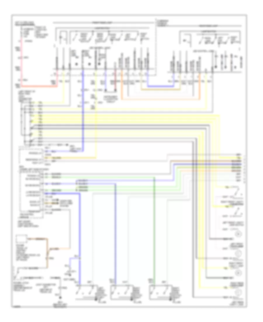 https://portal-diagnostov.com/license.html
Automotive Electricians Portal FZCO
Automotive Electricians Portal FZCO
https://portal-diagnostov.com/license.html
https://portal-diagnostov.com/license.html
Automotive Electricians Portal FZCO
Automotive Electricians Portal FZCOList of elements for Courtesy Lamps Wiring Diagram (1 of 4) for Hyundai Equus Ultimate 2014:
- (left front of roof trim) joint connector jr01
- (not used)
- Acc/on in
- B-can hi
- B-can lo
- Back up lp sig
- Bcm (under left side of dash)
- Computer data lines system
- Door lamp switch
- Door sig
- Foot lp
- Fr room lp
- Fr02
- Fr11
- Fr21
- Front room lamp
- Front room lamp switch
- Frt dr open sig
- Gf01 (left kick panel)
- Gf10 (behind left rear seat)
- Gnd
- Hot w/ pdm (acc) relay energized
- I/p-lhb
- I/p-lhf
- I/p-rhd
- Ill
- Ill (+)
- Ill (-)
- Instrument illumination circuit
- Interior lamp fuse 10a
- Ips control module
- Joint connector jr11 (center of trunk lid)
- Lamp switch
- Led control logic
- Left front door switch (left "b" pillar)
- Left front vanity lamp
- Left front vanity lamp switch
- Left map lamp
- Left map switch
- Left rear vanity lamp
- Left smart junction box (left end of dash)
- Lh fr dr sw
- Lh rr dr sw
- Lp on/off sig rr room
- Lp sig rr room
- Lp state sig rr room
- Lp sw sig rr room
- M32-b
- M32-c
- Mf11
- Mf21
- Nca
- Overhead console assembly
- Power latch assembly (center rear of trunk lid)
- Power trunk lid control module (w/ power trunk lid) (left front of trunk)
- Rear room lamp
- Rear room lamp switch
- Rear room lp
- Rh fr dr sw
- Rh rr dr sw
- Right front door switch (right "b" pillar)
- Right front vanity lamp
- Right front vanity lamp switch
- Right i/p junction box (right end of dash)
- Right map lamp
- Right map switch
- Right rear door switch (right "c" pillar)
- Right rear vanity lamp
- Room lamp
- Room lamp switch
- Rr dr open sig
- Tr room lp
- Trunk sw
Courtesy Lamps Wiring Diagram (2 of 4) for Hyundai Equus Ultimate 2014
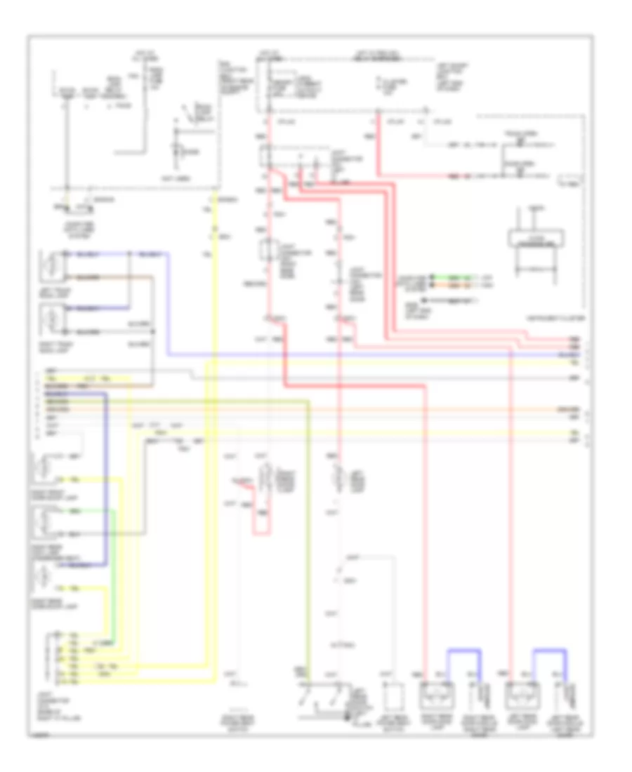 https://portal-diagnostov.com/license.html
Automotive Electricians Portal FZCO
Automotive Electricians Portal FZCO
https://portal-diagnostov.com/license.html
https://portal-diagnostov.com/license.html
Automotive Electricians Portal FZCO
Automotive Electricians Portal FZCOList of elements for Courtesy Lamps Wiring Diagram (2 of 4) for Hyundai Equus Ultimate 2014:
- (not used)
- 5v reg
- B-can high
- B-can low
- C-can transceiver
- Cluster fuse 10a
- Computer data lines system
- Dd31
- Dd41
- Diode
- Door open ind
- E/r junction box (right rear of engine compt)
- E/r-e1b
- E/r-e2a
- Ef21
- Fam
- Fam-b
- Fd31
- Fd41
- Fr21
- Fs21
- Gm06 (left end of dash)
- High
- Hot at all times
- Hot w/ pdm (ig1) relay energized
- I/p-lhc
- I/p-lhf
- I/p-lhg
- Instrument cluster
- Joint connector jd31 (left rear door)
- Joint connector jd41 (right rear door)
- Joint connector jf01 (left "c" pillar)
- Joint connector jf12 (base of right "c" pillar)
- Leak current autocut device
- Left rear door lamp
- Left rear door module (left rear door)
- Left rear door mood lamp
- Left rear door switch (left "c" pillar)
- Left rear power seat switch
- Left smart junction box (left end of dash)
- Left trunk room lamp
- Lh rr door lp
- Low
- Memory fuse 10a
- Mf21
- Micom
- Red
- Rh rr door lp
- Right front door scuff lamp
- Right rear door lamp
- Right rear door module (right rear door)
- Right rear door mood lamp
- Right rear door scuff lamp
- Right rear foot lamp (passenger seat)
- Right rear power seat switch
- Right trunk room lamp
- Room lamp fuse 10a
- Room lamp relay
- Room lamp relay control
- Trunk open ind
Courtesy Lamps Wiring Diagram (3 of 4) for Hyundai Equus Ultimate 2014
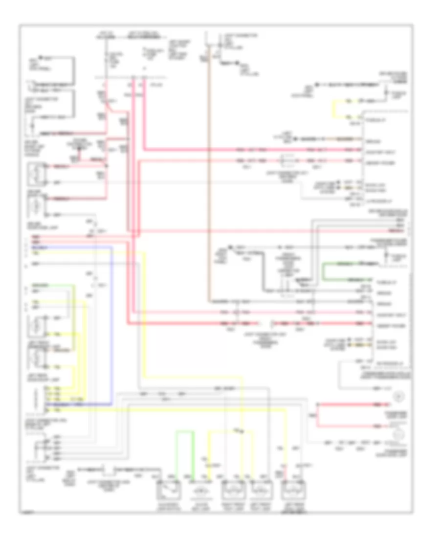 https://portal-diagnostov.com/license.html
Automotive Electricians Portal FZCO
Automotive Electricians Portal FZCO
https://portal-diagnostov.com/license.html
https://portal-diagnostov.com/license.html
Automotive Electricians Portal FZCO
Automotive Electricians Portal FZCOList of elements for Courtesy Lamps Wiring Diagram (3 of 4) for Hyundai Equus Ultimate 2014:
- (front passenger's door) joint connector jd21
- (left "c" pillar) gf03
- B-can high
- B-can low
- Computer data lines system
- D51-b
- D51-c
- D61-a
- D61-b
- D61-c
- Dd11
- Dd21
- Door)
- Driver
- Driver door lamp
- Driver door module (driver's door)
- Driver door mood lamp
- Driver power outside mirror
- Fd11
- Fd21
- Ff01
- Fs11
- Gf01 (left kick panel)
- Gf03 (left "c" pillar)
- Gf05 (right kick panel)
- Glove box lamp
- Glove box lamp switch
- Gm01 (left end of dash)
- Ground
- Hot at all times
- Hot w/ pdm (ig1) relay energized
- I/p-lhc
- Joint connector jd11 (driver's door)
- Joint connector jd21 (front passenger's
- Joint connector jf01 (left "c" pillar)
- Joint connector jf02 (base of left "c" pillar)
- Joint connector jm05 (center of dash)
- Left front door scuff lamp
- Left front foot lamp
- Left rear door scuff lamp
- Left rear foot lamp (driver seat)
- Left smart junction box (left end of dash)
- Lh fr door lp
- Memory power
- Mf11
- Mm01
- Module 4 fuse 10a
- Nca
- O/s hdl drv fuse 15a
- On/start input
- Passenger door lamp
- Passenger door module (front passenger's door)
- Passenger door mood lamp
- Passenger power outside mirror
- Pnk
- Power distribution system
- Puddle lamp
- Puddle lp
- Red
- Rh fr door lp
- Right front foot lamp
- Smart key outside handle
Courtesy Lamps Wiring Diagram (4 of 4) for Hyundai Equus Ultimate 2014
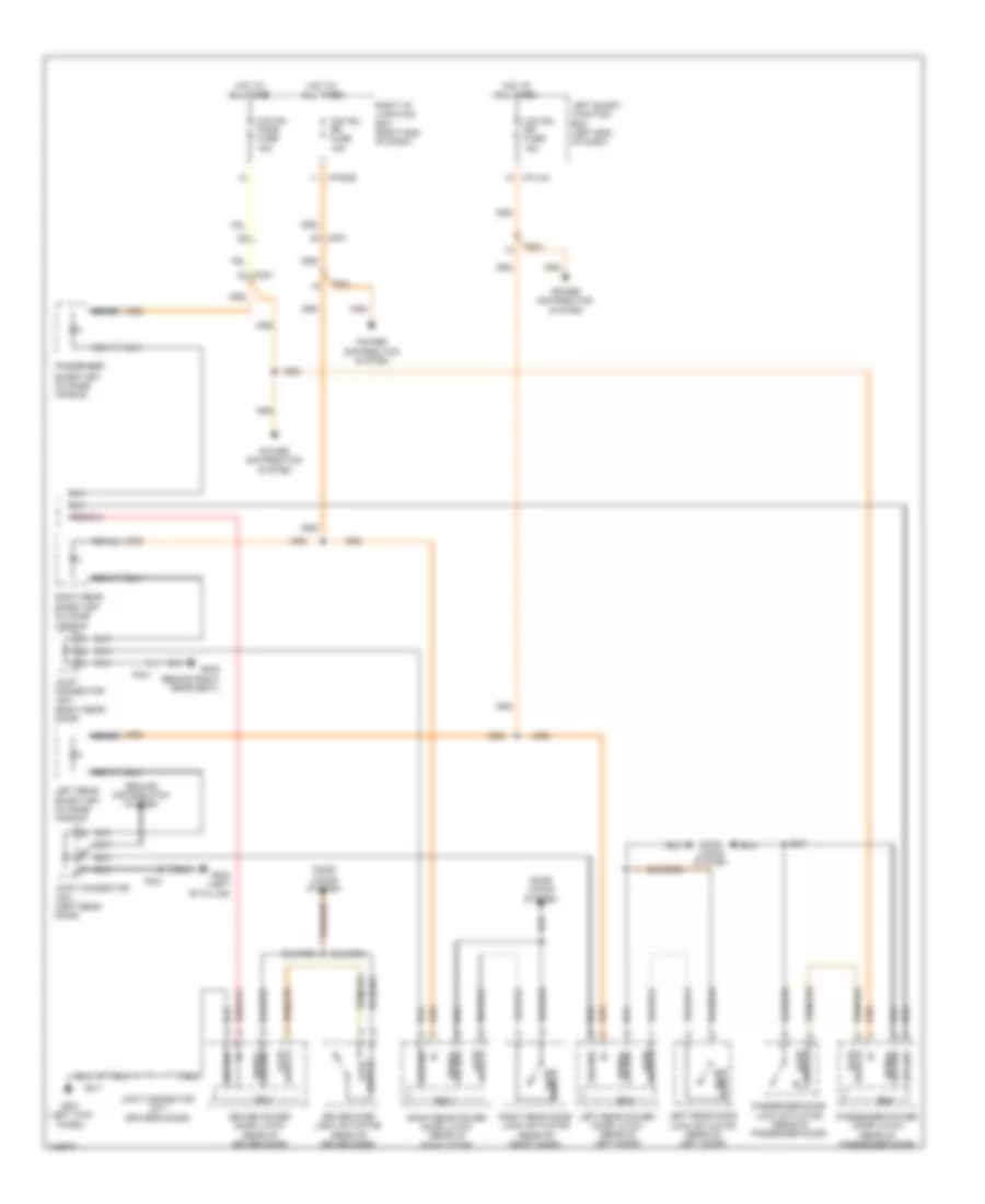 https://portal-diagnostov.com/license.html
Automotive Electricians Portal FZCO
Automotive Electricians Portal FZCO
https://portal-diagnostov.com/license.html
https://portal-diagnostov.com/license.html
Automotive Electricians Portal FZCO
Automotive Electricians Portal FZCOList of elements for Courtesy Lamps Wiring Diagram (4 of 4) for Hyundai Equus Ultimate 2014:
- Ajar switch
- Door locks system
- Driver door lock actuator (rear of driver door)
- Driver power door latch (rear of driver door)
- Ecu
- Fd11
- Fd21
- Fd31
- Fd41
- Gf01 (left kick panel)
- Gf02 (left "b" pillar)
- Gf09 (behind right rear seat)
- Ground
- Ground distribution system
- Ground signal
- Hot at all times
- I/p-lhc
- I/p-rhe
- Joint connector jd11 (driver's door)
- Joint connector jd31 (left rear door)
- Joint connector jd41 (right rear door)
- Left rear door lock actuator (rear of left door)
- Left rear power door latch (rear of left door)
- Left rear smart key outside handle
- Left smart junction box (left end of dash)
- Mf21
- Nca
- O/s hdl pass fuse 15a
- O/s hdl rr fuse 15a
- Passenger
- Passenger door lock actuator (rear of passenger door)
- Passenger power door latch (rear of passenger door)
- Power distribution system
- Right i/p junction box (right end of dash)
- Right rear
- Right rear door lock actuator (rear of right door)
- Right rear power door latch (rear of right door)
- Smart key outside handle
- Switch ajar
Instrument Illumination Wiring Diagram (1 of 4) for Hyundai Equus Ultimate 2014
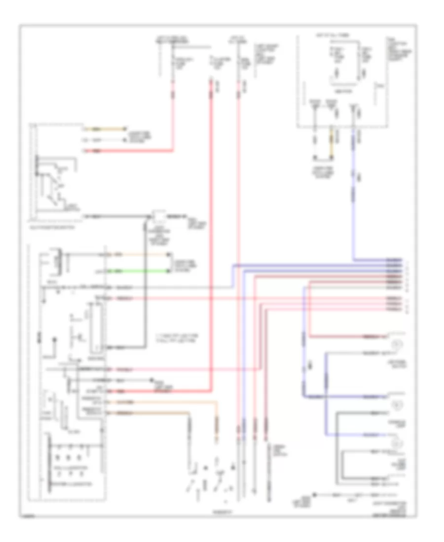 https://portal-diagnostov.com/license.html
Automotive Electricians Portal FZCO
Automotive Electricians Portal FZCO
https://portal-diagnostov.com/license.html
https://portal-diagnostov.com/license.html
Automotive Electricians Portal FZCO
Automotive Electricians Portal FZCOList of elements for Instrument Illumination Wiring Diagram (1 of 4) for Hyundai Equus Ultimate 2014:
- 5v reg
- 5v sw
- 7 inch tft lcd type
- Auto
- B-can high
- B-can low
- Cconstant current circuit
- Cluster fuse 10a
- Computer data lines system
- Console lamp
- Crash pad switch
- Cup holder lamp
- Detent out
- Dial illumination
- Down
- E/r junction box (right rear of engine compt)
- E/r-e1b
- E/r-e2a
- Em41
- Epb fuse 10a
- Fam
- Fam 1 (b+) fuse 40a
- Fam 2 (b+) fuse 40a
- Fam-a
- Fam-b
- Fam-c
- Full tft lcd type
- Gm01 (left end of dash)
- Gm06 (left end of dash)
- Hot at all times
- Hot w/ pdm (ig1) relay energized
- I/f
- I/p-lhf
- I/p-lhg
- Ill (-)
- Ill(+)
- Instrument cluster (detent)
- Joint connector jm03 (right end of dash)
- Joint connector jm21 (rear of center console)
- Lcd panel switch
- Left smart junction box (left end of dash)
- Light
- Low
- M/f sw ecu
- Mem pwr
- Micom
- Mm11
- Module 4 fuse 10a
- Multi-function switch
- Off
- On/ start in
- Pointer illumination
- Red
- Rheostat
- Rheostat down in
- Rheostat up in
- S gnd
- Sig2 gnd
- Switch
- Tail lamp in
- Transceiver c-can
Instrument Illumination Wiring Diagram (2 of 4) for Hyundai Equus Ultimate 2014
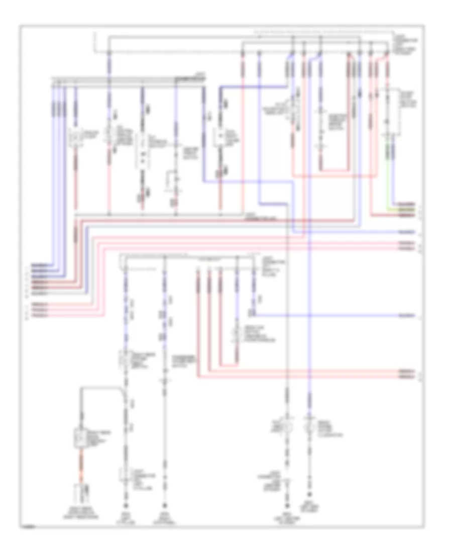 https://portal-diagnostov.com/license.html
Automotive Electricians Portal FZCO
Automotive Electricians Portal FZCO
https://portal-diagnostov.com/license.html
https://portal-diagnostov.com/license.html
Automotive Electricians Portal FZCO
Automotive Electricians Portal FZCOList of elements for Instrument Illumination Wiring Diagram (2 of 4) for Hyundai Equus Ultimate 2014:
- A/c control module (center of dash) m07-c
- A/t console switch
- A/v & navigation head unit
- Analog clock
- Atm shift lever ind
- Aux usb jack
- Center fascia switch
- Dd21
- Dd41
- Electric parking brake switch
- Fd21
- Fd41
- Ff01
- Front dis switch (center of floor console)
- Front power outlet illumination
- Gf03 (left "c" pillar)
- Gf05 (right kick panel)
- Gm01 (left end of dash)
- Gm03 (left center of dash)
- Joint connector jf01 (left "c" pillar)
- Joint connector jf11 (right "c" pillar)
- Joint connector jm05 (center of dash)
- Joint connector jm07 (right end of dash)
- Joint connector umc
- Joint connector umd
- Lamp ashtray
- M03-a
- M07-c
- Mf11
- Mm02
- Mm11
- Nca
- Passenger power seat switch
- Right rear door ashtray lamp
- Right rear door module (right rear door)
- Right rear power seat switch
- Start stop button switch
Instrument Illumination Wiring Diagram (3 of 4) for Hyundai Equus Ultimate 2014
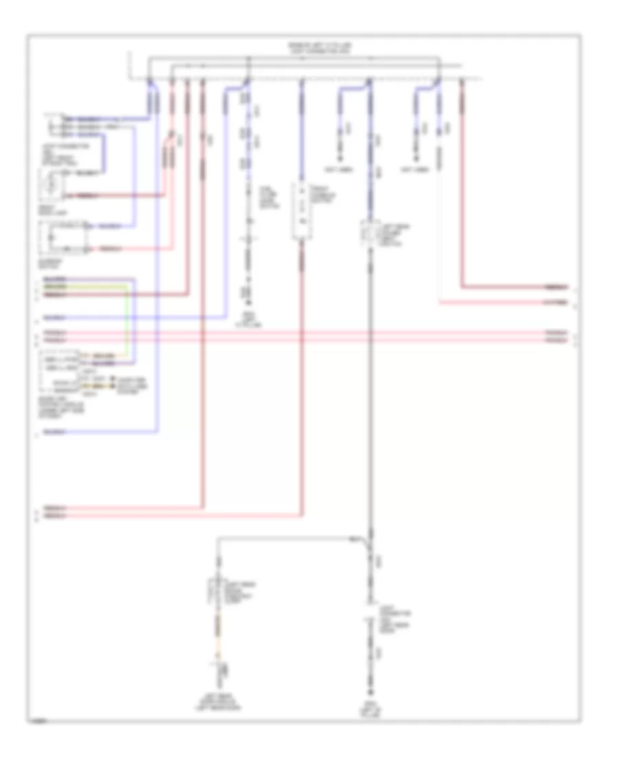 https://portal-diagnostov.com/license.html
Automotive Electricians Portal FZCO
Automotive Electricians Portal FZCO
https://portal-diagnostov.com/license.html
https://portal-diagnostov.com/license.html
Automotive Electricians Portal FZCO
Automotive Electricians Portal FZCOList of elements for Instrument Illumination Wiring Diagram (3 of 4) for Hyundai Equus Ultimate 2014:
- (base of left "c" pillar) joint connector jf02
- (not used)
- B-can hi
- B-can lo
- Computer data lines system
- Dd11
- Dd31
- Fd11
- Fd31
- Ff01
- Fr11
- Front console switch
- Front room lamp
- Fs11
- Fs31
- Fs41
- Fuel filler door switch
- Gf02 (left "b" pillar)
- Gf03 (left "c" pillar)
- Joint connector jd31 (left rear door)
- Joint connector jr01 (left front of roof trim)
- Lamp ashtray
- Left rear door ashtray lamp
- Left rear door module (left rear door)
- Left rear power seat switch
- M30-a
- M30-c
- Nca
- Smart key control module (under left side of dash)
- Ssb ill gnd
- Ssb ill pwr
- Sunroof switch
Instrument Illumination Wiring Diagram (4 of 4) for Hyundai Equus Ultimate 2014
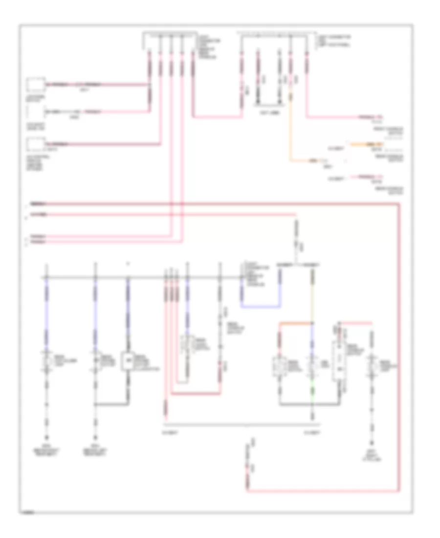 https://portal-diagnostov.com/license.html
Automotive Electricians Portal FZCO
Automotive Electricians Portal FZCO
https://portal-diagnostov.com/license.html
https://portal-diagnostov.com/license.html
Automotive Electricians Portal FZCO
Automotive Electricians Portal FZCOList of elements for Instrument Illumination Wiring Diagram (4 of 4) for Hyundai Equus Ultimate 2014:
- (not used)
- 5:5 seat
- 6:4 seat
- A/c control module (center of dash)
- Atm shift level ind
- F11-a
- Front console switch
- Fs11
- Fs31
- Fs41
- Gf04 (behind left rear seat)
- Gf07 (right "c" pillar)
- Gf08 (behind right rear seat)
- Joint connector jf03 (left kick panel)
- Joint connector jm06 (rear of rear console)
- Joint connector js41 (rear of rear console)
- Lcd panel switch
- M07-c
- Mf11
- Mm02
- Mm11
- Nca
- Rear audio switch
- Rear console lamp
- Rear console switch
- Rear cup holder lamp
- Rear power outlet
- Rear power outlet illumination
- S27-a
- S27-b
- S37-a
- S37-b
- Ss31
- Usb jack
MEMORY SYSTEMS
Driver"s Memory Seat Wiring Diagram (1 of 2) for Hyundai Equus Ultimate 2014
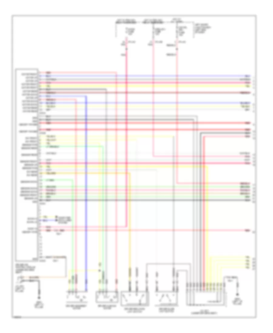 https://portal-diagnostov.com/license.html
Automotive Electricians Portal FZCO
Automotive Electricians Portal FZCO
https://portal-diagnostov.com/license.html
https://portal-diagnostov.com/license.html
Automotive Electricians Portal FZCO
Automotive Electricians Portal FZCOList of elements for Driver"s Memory Seat Wiring Diagram (1 of 2) for Hyundai Equus Ultimate 2014:
- A/con fuse 10a
- B-can hi
- B-can lo
- Computer data lines system
- Driver cushion motor
- Driver headrest motor
- Driver ims control module (under driver's seat)
- Driver reclining limit switch
- Driver slide limit switch
- Fs11
- Gf02 (left ``b" pillar)
- Gf03 (left "c" pillar)
- Gnd
- Hot at all times
- Hot w/ pdm (ig1) relay energized
- I/p-lhc
- I/p-lhe
- J/c jf01 (left "c" pillar)
- J/c js11 (under driver's seat)
- Left smart junction box (left end of dash)
- Memory power
- Memory pwr
- Module 4 fuse 10a
- Motor down
- Motor front
- Motor rear
- Motor up
- Nca
- O/s hdl drv fuse 15a
- On/st in
- Pnk
- Red
- S16-a
- S16-b
- S16-c
- S16-d
- Sensor down
- Sensor front
- Sensor pwr
- Sensor rear
- Sensor up
- Sw front
- Sw rear
Driver"s Memory Seat Wiring Diagram (2 of 2) for Hyundai Equus Ultimate 2014
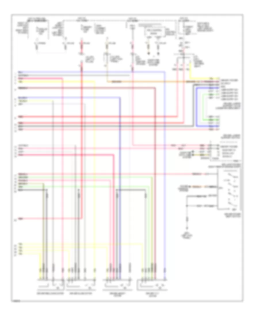 https://portal-diagnostov.com/license.html
Automotive Electricians Portal FZCO
Automotive Electricians Portal FZCO
https://portal-diagnostov.com/license.html
https://portal-diagnostov.com/license.html
Automotive Electricians Portal FZCO
Automotive Electricians Portal FZCOList of elements for Driver"s Memory Seat Wiring Diagram (2 of 2) for Hyundai Equus Ultimate 2014:
- B-can
- B-can hi
- B-can low
- Computer data lines system
- Cpu
- Driver height motor
- Driver lumbar support switch
- Driver lumbar support valve (under driver's seat)
- Driver power seat switch
- Driver reclining motor
- Driver slide motor
- Driver tilt motor
- E/r fuse & relay box (left side of engine compt)
- E/r junction box (right rear of engine compt)
- E/r-e1b
- Ef11
- Em21
- Fam
- Fam-b
- Fs11
- Gf01 (left kick panel)
- Gnd
- High
- Hot at all times
- Hot w/ pdm (ig2) relay energized
- I/p-lhb
- I/p-lhc
- I/p-lhf
- I/p-lhg
- I/p-rhd
- Ips 3 (1ch)
- Ips 3 control
- Ips control module
- J/c jf01 (left "c" pillar)
- J/c jf03 (left kick panel)
- J/c jm01 (center of dash)
- J/c js11 (under driver's seat)
- Leak current autocut device
- Led gnd
- Left smart junction box (left end of dash)
- Lmbr suprt sw
- Low
- Memory fuse 10a
- Memory power
- Module fuse 10a
- On input
- On/start in
- P/seat (drv) fuse 30a
- Pnk
- Power windows system
- Red
- Right i/p junction box (right end of dash)
- Serial
- Set
Memory Mirrors Wiring Diagram (1 of 2) for Hyundai Equus Ultimate 2014
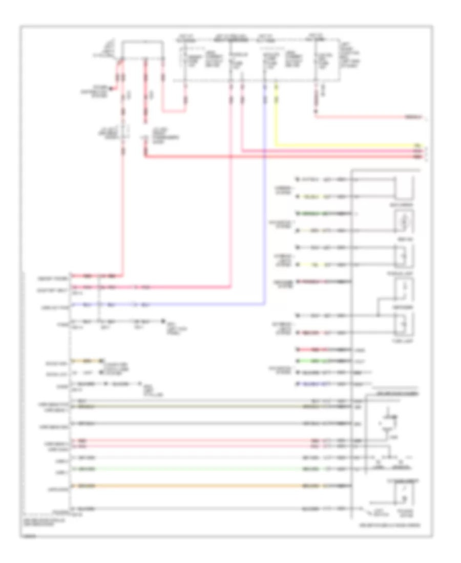 https://portal-diagnostov.com/license.html
Automotive Electricians Portal FZCO
Automotive Electricians Portal FZCO
https://portal-diagnostov.com/license.html
https://portal-diagnostov.com/license.html
Automotive Electricians Portal FZCO
Automotive Electricians Portal FZCOList of elements for Memory Mirrors Wiring Diagram (1 of 2) for Hyundai Equus Ultimate 2014:
- (+)
- (-)
- B-can high
- B-can low
- Bsd ind
- Computer data lines system
- D51-a
- D51-c
- Dd11
- Defogger
- Defogger system
- Driver door camera
- Driver door module (driver's door)
- Driver power outside mirror
- Ecm mirror
- Exterior lights system
- Fd11
- Fd21
- Fold'g mirr fuse 10a
- Folding d51-b
- Folding motor
- Gf01 (left kick panel)
- Gf03 (left "c" pillar)
- Gnd
- Hor
- Hot at all times
- Hot w/ pdm (ig1) relay energized
- I/p-lhc
- Interior lights system
- J/c jd11 (driver's door)
- J/c jd21 (front passenger's door)
- J/c jf01 (left "c" pillar)
- Leak current autocut device
- Left smart junction box (left end of dash)
- Lh/rh
- Limit switch
- Memory fuse 10a
- Memory power
- Mirr act pwr
- Mirr comm
- Mirr h
- Mirr sens gnd
- Mirr sens h
- Mirr sens pwr
- Mirr sens v
- Mirr v
- Mirrors system
- Module fuse 10a
- Navigation system
- Nca
- O/s hdl drv fuse 15a
- On/start input
- Outside mirror
- P-gnd
- Pnk
- Power distribution system
- Puddle lamp
- Pwr
- Red
- S-gnd
- Turn lamp
- Unfolding
- Up/down
- V-gnd
- V-out
- Ver
Memory Mirrors Wiring Diagram (2 of 2) for Hyundai Equus Ultimate 2014
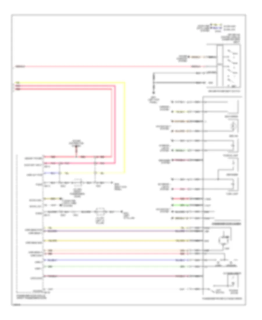 https://portal-diagnostov.com/license.html
Automotive Electricians Portal FZCO
Automotive Electricians Portal FZCO
https://portal-diagnostov.com/license.html
https://portal-diagnostov.com/license.html
Automotive Electricians Portal FZCO
Automotive Electricians Portal FZCOList of elements for Memory Mirrors Wiring Diagram (2 of 2) for Hyundai Equus Ultimate 2014:
- (+)
- (-)
- B can high
- B can low
- B-can high
- B-can low
- Bsd ind
- Computer data lines system
- Cpu
- D61-a
- D61-c
- Dd21
- Defogger
- Defogger system
- Driver ims control module (under driver's seat)
- Driver power seat switch
- Ecm mirror
- Exterior lights system
- Fd21
- Folding d61-b
- Folding motor
- Gf01 (left kick panel)
- Gf03 (left "c" pillar)
- Gf05 (right kick panel)
- Gnd
- Hor
- Interior lights system
- J/c jd21 (front passenger's door)
- J/c jf01 (left "c" pillar)
- Led gnd
- Lh/rh
- Limit switch
- Memory power
- Mirr act pwr
- Mirr comm
- Mirr h
- Mirr sens gnd
- Mirr sens h
- Mirr sens pwr
- Mirr sens v
- Mirr v
- Mirrors system
- Navigation system
- Nca
- On/start input
- Outside mirror
- P-gnd
- Passenger door camera
- Passenger door module (front passenger's door)
- Passenger power outside mirror
- Pnk
- Power distribution system
- Power windows system
- Puddle lamp
- Pwr
- Red
- S-gnd
- S16-d
- Serial
- Set
- Turn lamp
- Unfolding
- Up/down
- V-gnd
- V-out
- Ver
Memory Power Tilt & Power Telescopic Wiring Diagram for Hyundai Equus Ultimate 2014
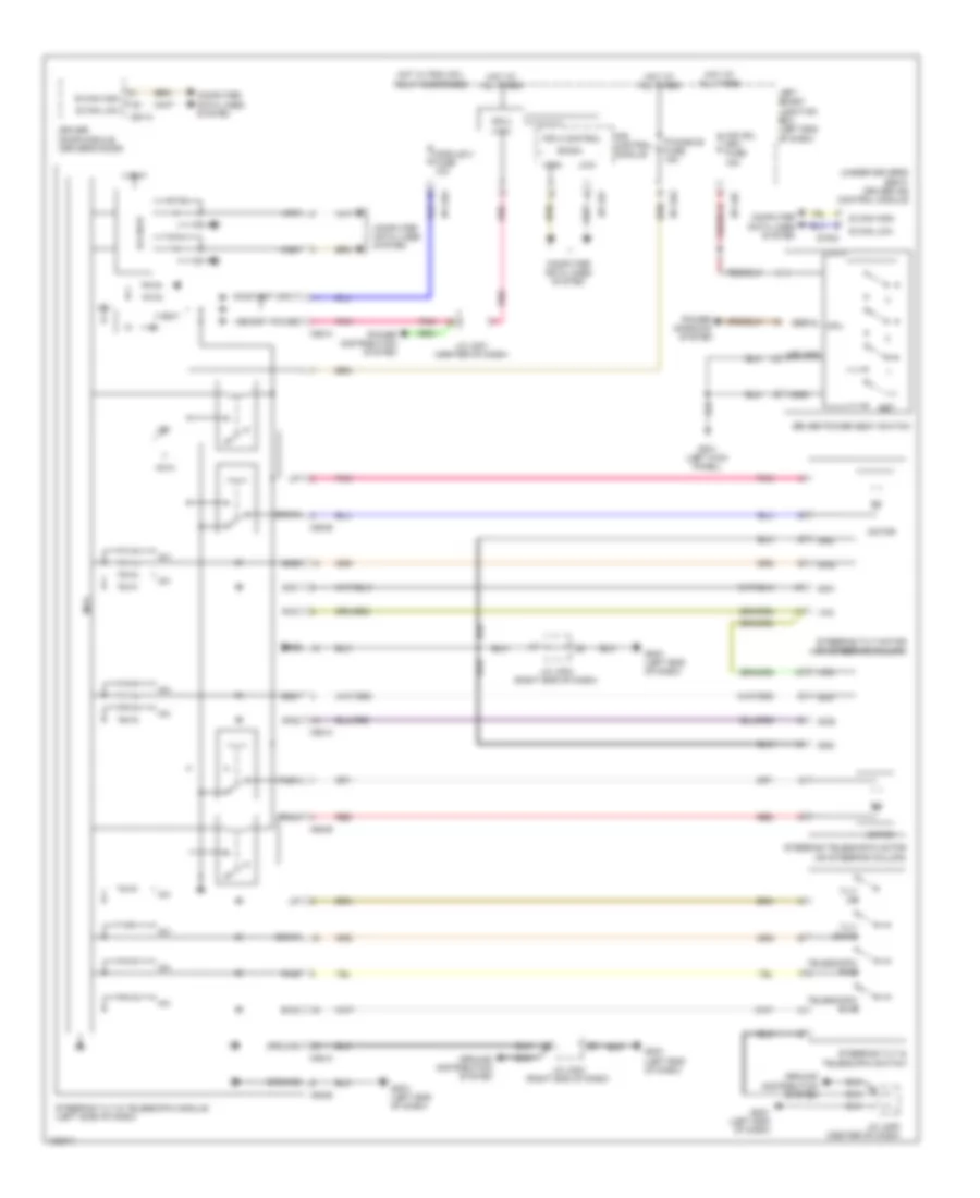 https://portal-diagnostov.com/license.html
Automotive Electricians Portal FZCO
Automotive Electricians Portal FZCO
https://portal-diagnostov.com/license.html
https://portal-diagnostov.com/license.html
Automotive Electricians Portal FZCO
Automotive Electricians Portal FZCOList of elements for Memory Power Tilt & Power Telescopic Wiring Diagram for Hyundai Equus Ultimate 2014:
- (under driver's seat) driver ims control module
- +5v
- +5va
- +vbat
- B can high
- B can low
- B-can
- B-can ic
- Bwd
- Computer data lines system
- Cpu
- D51-c
- Down
- Driver door module (driver's door)
- Driver power seat switch
- Fwd
- Gf01 (left kick panel)
- Gm01 (left end of dash)
- Gnd
- Ground
- Ground distribution system
- High
- Hot at all times
- Hot w/ pdm (ig1) relay energized
- I/p-lhc
- I/p-lhf
- I/p-lhg
- Ips 3 (1ch)
- Ips 3 control
- Ips control module
- J/c jm01 (center of dash)
- J/c jm03 (right end of dash)
- J/c jm05 (center of dash)
- Led gnd
- Left smart junction box (left end of dash)
- Low
- M52-a
- M52-b
- Mcu
- Memory power
- Module 3 fuse 10a
- Motor
- O/s hdl drv fuse 15a
- On/start input
- P/handle fuse 15a
- Pnk
- Power distribution system
- Power windows system
- Pull
- Push
- Red
- S16-d
- Serial
- Set
- Sig1
- Sig2
- Steering telescopic motor (on steering column)
- Steering tilt & telescopic module (left side of dash)
- Steering tilt & telescopic switch
- Steering tilt motor (on steering column)
- Telescopic bwd
- Telescopic fwd
- Tilt down
- Tilt up
- Vcc
NAVIGATION
All Around Vision Camera Wiring Diagram for Hyundai Equus Ultimate 2014
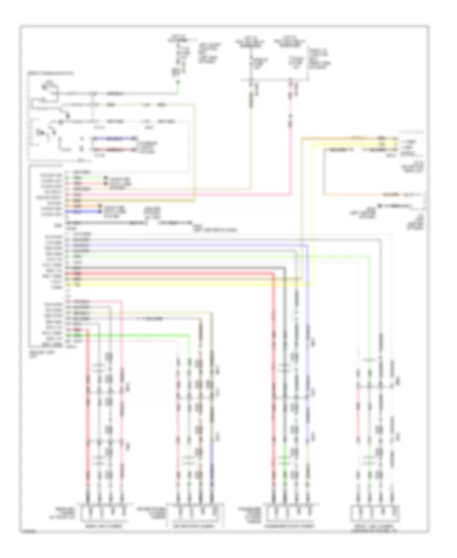 https://portal-diagnostov.com/license.html
Automotive Electricians Portal FZCO
Automotive Electricians Portal FZCO
https://portal-diagnostov.com/license.html
https://portal-diagnostov.com/license.html
Automotive Electricians Portal FZCO
Automotive Electricians Portal FZCOList of elements for All Around Vision Camera Wiring Diagram for Hyundai Equus Ultimate 2014:
- (center of dash) j/c jm05
- A/v & navigation head unit
- Acc/on input
- Around view unit
- Audio fuse 10a
- Avm sw
- Avm sw ind
- Avm switch
- C-can high
- C-can low
- Computer data lines system
- Cpu
- Dd11
- Dd21
- Ddc gnd
- Ddc pwr
- Ddc v-gnd
- Ddc v-in
- Driver door camera
- Driver power outside mirror
- Ee41
- Em31
- F11-a
- F11-b
- Fd11
- Fd21
- Fr02
- Front console switch
- Front view camera (center of top grille)
- Fuse 10a
- Fvc gnd
- Fvc pwr
- Fvc v-gnd
- Fvc v-in
- Gm03 (left center of dash)
- Gnd
- Hot at all times
- Hot w/ pdm (acc) relay energized
- Hot w/ pdm (ig2) relay energized
- I/p-lhc
- I/p-rhd
- I/p-rhe
- Ill
- Interior lights system
- J/c jm05 (center of dash)
- Left smart junction box (left end of dash)
- M-can high
- M-can low
- M03-a
- M04-a
- M04-b
- Mf11
- Mf21
- Module fuse 10a
- Nca
- On input
- Passenger door camera
- Passenger power outside mirror
- Pdc gnd
- Pdc pwr
- Pdc v-gnd
- Pdc v-in
- Pnk
- Pwr
- Rear view camera
- Rearview camera (in trunk lid)
- Red
- Right i/p junction box (right end of dash)
- Rvc gnd
- Rvc pwr
- Rvc v-gnd
- Rvc v-in
- Shield
- T/lid
- V gnd
- V video
- V-gnd
- V-out
Blind Spot Information System Wiring Diagram for Hyundai Equus Ultimate 2014
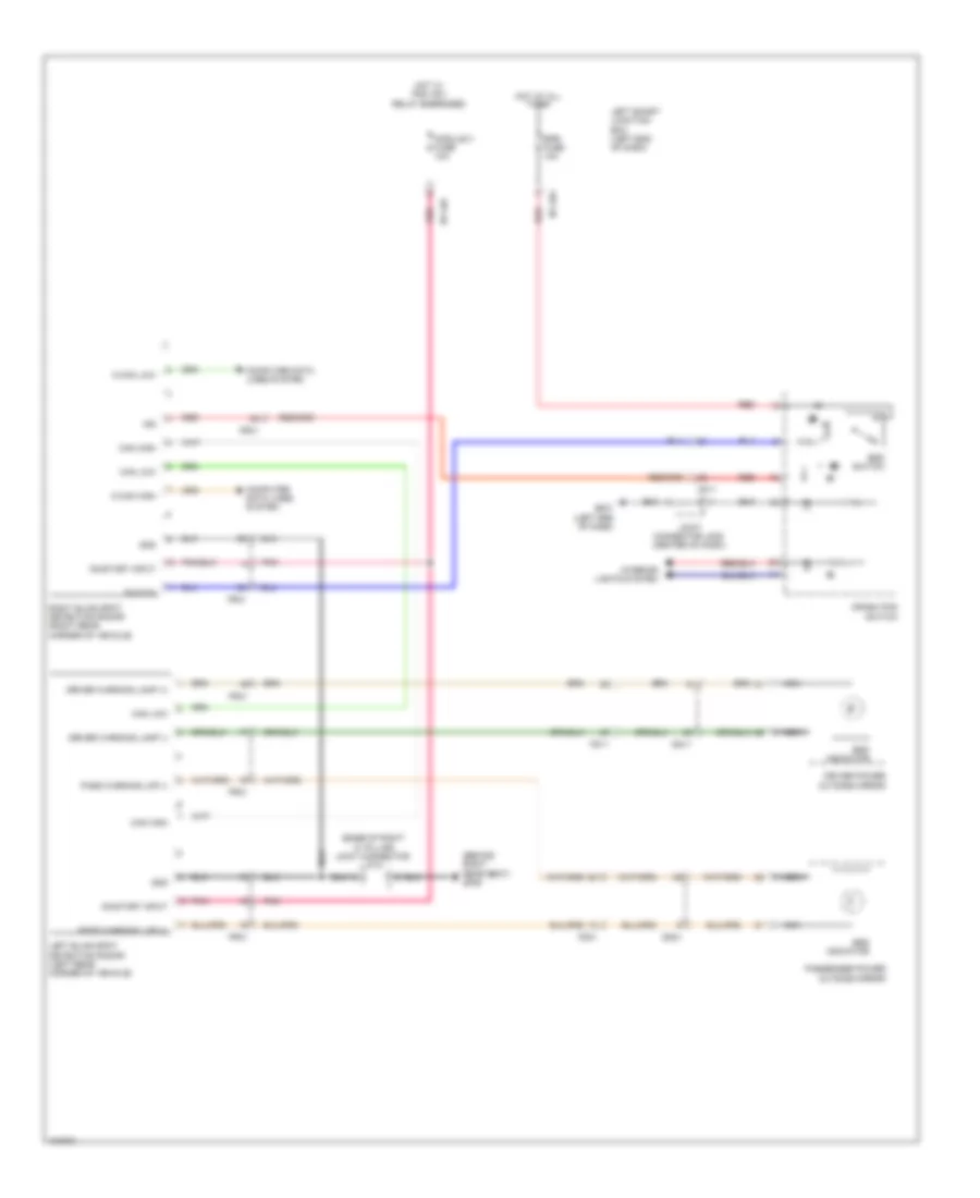 https://portal-diagnostov.com/license.html
Automotive Electricians Portal FZCO
Automotive Electricians Portal FZCO
https://portal-diagnostov.com/license.html
https://portal-diagnostov.com/license.html
Automotive Electricians Portal FZCO
Automotive Electricians Portal FZCOList of elements for Blind Spot Information System Wiring Diagram for Hyundai Equus Ultimate 2014:
- (base of right "c" pillar) joint connector jf12
- (behind right rear seat) gf09
- Bsd indicator
- Bsd switch
- C-can high
- C-can low
- Can high
- Can low
- Computer data lines system
- Crash pad
- Dd11
- Dd21
- Detection radar (left rear corner of vehicle)
- Driver power
- Driver warning lamp (+)
- Driver warning lamp (-)
- Epb fuse 10a
- Fd11
- Fd21
- Fr31
- Gm01 (left end of dash)
- Gnd
- Hot at all times
- Hot w/ pdm (ig1) relay energized
- I/p-lhc
- I/p-lhg
- Ind
- Interior lights system
- Joint connector jm05 (center of dash)
- Left blind spot
- Left smart junction box (left end of dash)
- Mf11
- Module 3 fuse 10a
- Nca
- On/start input
- Outside mirror
- Pass warning lmp (+)
- Pass warning lmp (-)
- Passenger power outside mirror
- Pnk
- Red
- Right blind spot detection radar (right rear corner of vehicle)
- Switch
Lane Departure Warning Wiring Diagram for Hyundai Equus Ultimate 2014
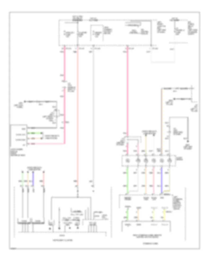 https://portal-diagnostov.com/license.html
Automotive Electricians Portal FZCO
Automotive Electricians Portal FZCO
https://portal-diagnostov.com/license.html
https://portal-diagnostov.com/license.html
Automotive Electricians Portal FZCO
Automotive Electricians Portal FZCOList of elements for Lane Departure Warning Wiring Diagram for Hyundai Equus Ultimate 2014:
- (7 inch tft lcd)
- (full tft lcd)
- 1.2v reg
- 1.5v/1.275v reg
- 1.8v reg
- 3.3v reg
- Agnd
- B-can high
- B-can low
- C-can high
- C-can low
- C-can transceiver
- Clock spring
- Cluster fuse 10a
- Computer data
- Computer data lines system
- E/r fuse & relay box (left side of engine compt)
- Fr11
- Fr21
- Gf01 (left kick panel)
- Gf03 (left "c" pillar)
- Gm01 (left end of dash)
- Gnd
- H ill (+)
- H ill (-)
- High
- Hot at all times
- Hot w/ pdm (ig1) relay energized
- I/p power lh fuse 80a
- I/p-lhc
- I/p-lhd
- I/p-lhf
- I/p-lhg
- Ig1
- Instrument cluster
- Ips 3 (1ch)
- Ips 3 control
- Ips control module
- J/c jf01 (left "c" pillar)
- J/c jf12 (base of right "c" pillar)
- J/c jm01 (center of dash)
- J/c jm03 (right end of dash)
- J/c jr01 (left front of roof trim)
- Ldws
- Ldws camera module (front center of roof)
- Ldws fail (7" tft)
- Leak current autocut device
- Left smart junction box (left end of dash)
- Left steering wheel remote control switch (down)
- Lines system
- Low
- M-can transceiver
- M93-dl1
- Memory fuse 10a
- Memory power
- Mf11
- Micom
- Module 3 fuse 10a
- Pnk
- Red
- Right steering wheel remote control switch (down)
- Signal
- Steering wheel
- Tft lcd
- Tft lcd driver
Mobile Telematic System Wiring Diagram for Hyundai Equus Ultimate 2014
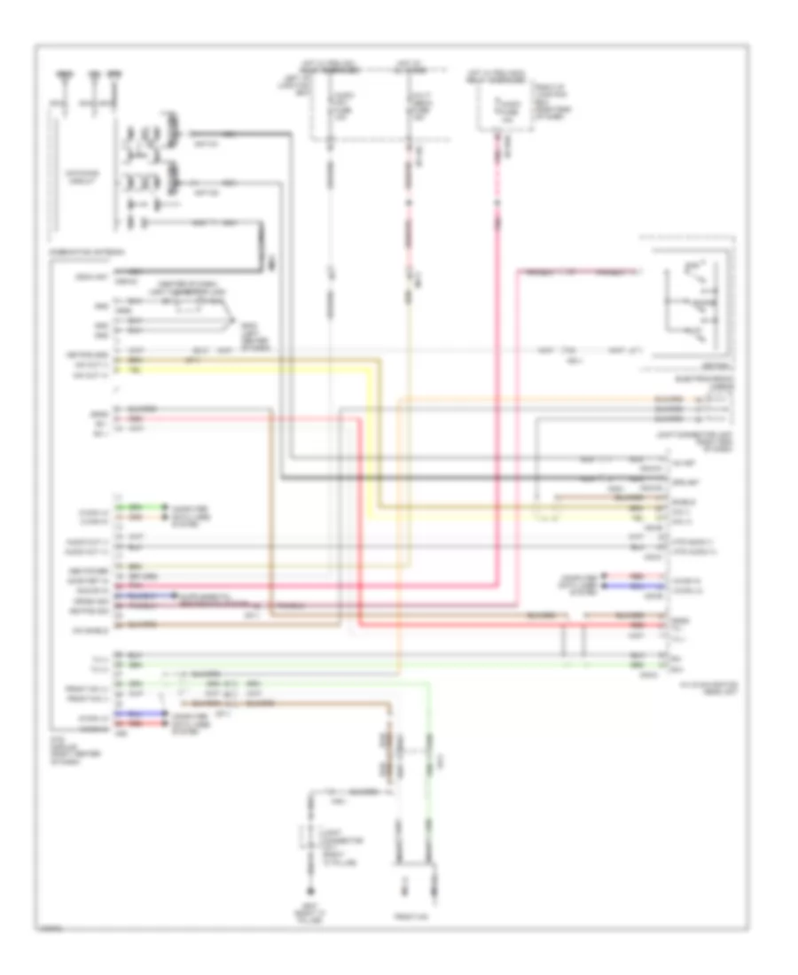 https://portal-diagnostov.com/license.html
Automotive Electricians Portal FZCO
Automotive Electricians Portal FZCO
https://portal-diagnostov.com/license.html
https://portal-diagnostov.com/license.html
Automotive Electricians Portal FZCO
Automotive Electricians Portal FZCOList of elements for Mobile Telematic System Wiring Diagram for Hyundai Equus Ultimate 2014:
- (center of dash) joint connector jm05
- A/v & navigation head unit
- Acc/on in
- Ant-cg
- Ant-cx
- Audio
- Audio (ig1) fuse 10a
- Audio out (+)
- Audio out (-)
- Bpf
- C-can hi
- C-can lo
- Cdma
- Cdma ant
- Circuit
- Circuit matching
- Combination antenna
- Computer data lines system
- Crash sig
- Electrochromic mirror
- Fr11
- Front mic
- Front mic (+)
- Front mic (-)
- Fuse 10a
- Gf07 (right "c" pillar)
- Gm03 (left center of dash)
- Gnd
- Gps
- Gps ant
- Hot at all times
- Hot w/ pdm (acc) relay energized
- Hot w/ pdm (ig1) relay energized
- I/p-lhc
- I/p-rhe
- Joint connector jf11 (right "c" pillar)
- Joint connector jm07 (right end of dash)
- Keypad
- Keypad gnd
- Keypad sig
- Left i/p junction box
- Lna
- M-can hi
- M-can lo
- M03-b
- M03-c
- M03-cg
- M03-cx
- M06
- M06-cc
- M06g
- Matching
- Mem power
- Mf11
- Mic (+)
- Mic (-)
- Mic out (+)
- Mic out (-)
- Mic shield
- Mm21
- Mts audio (+)
- Mts audio (-)
- Mts module (right center of dash)
- Multi media fuse 15a
- Nca
- On/start in
- Phone
- Pnk
- Red
- Rfc
- Right i/p junction box (right end of dash)
- Rx +
- Rx -
- Rx+
- Rx-
- Sgnd
- Shield
- Sos
- Tx (+)
- Tx (-)
- Tx +
- Tx -
- Uvo
- Xm ant
Navigation Wiring Diagram (1 of 6) for Hyundai Equus Ultimate 2014
 https://portal-diagnostov.com/license.html
Automotive Electricians Portal FZCO
Automotive Electricians Portal FZCO
https://portal-diagnostov.com/license.html
https://portal-diagnostov.com/license.html
Automotive Electricians Portal FZCO
Automotive Electricians Portal FZCOList of elements for Navigation Wiring Diagram (1 of 6) for Hyundai Equus Ultimate 2014:
- (+)
- (-)
- (usb high speed cable)
- A/v & navigation head unit
- Acc/on input
- Am/fm
- Anfgr
- Ant-cg
- Ant-cx
- Audio (ig1) fuse 10a
- Aux detect
- Aux gnd
- Aux l
- Aux r
- Aux v gnd
- Aux v sig
- Backup sig
- Circuit
- Combination antenna
- Computer data lines system
- Cruise control system
- F04
- Fm2
- Fm2 ant
- Fr11
- Front mic
- Frt mic shield
- Gm03 (left center of dash)
- Gnd
- Gps
- Hot w/ pdm (ig1) relay energized
- I/p-lhg
- Ill (+)
- Ill (-)
- Interior lights system
- Interior lights system exterior lights system
- Joint connector jm05 (center of dash)
- Left glass antenna amp
- Left smart junction box (left end of dash)
- M-can hi
- M-can low
- M03-a
- M03-b
- M03-cg
- M03-cx
- Memory power
- Mf11
- Mf21
- Mic (+)
- Mic (-)
- Mm21
- Mm31
- Navi (+)
- Navi (-)
- Navigation system
- Nca
- On/start input
- Pnk
- Power
- Red
- Remote antenna
- Right glass antenna amp
- Rs485 (+)
- Rs485 (-)
- Rs485 gnd
- Shield
- Usb d (+)
- Usb d (-)
- Usb gnd
- Usb vcc
- V-gnd
- V-in
- Vehicle speed sig
- W/ mts
- W/o mts
Navigation Wiring Diagram (2 of 6) for Hyundai Equus Ultimate 2014
 https://portal-diagnostov.com/license.html
Automotive Electricians Portal FZCO
Automotive Electricians Portal FZCO
https://portal-diagnostov.com/license.html
https://portal-diagnostov.com/license.html
Automotive Electricians Portal FZCO
Automotive Electricians Portal FZCOList of elements for Navigation Wiring Diagram (2 of 6) for Hyundai Equus Ultimate 2014:
- (right "c" pillar) gf07
- (usb high speed cable)
- 6:4 seat
- A/v & navigation head unit
- Acc/on input
- Aux & usb jack
- Aux det
- Aux gnd
- Aux l
- Aux r
- Aux v sig
- Aux vgnd
- Computer data lines system
- Fr mic +
- Fr mic -
- Fr11
- Front mic
- Frt b/l on/off
- Fs31
- Gf07 (right "c" pillar)
- Gm03 (left center of dash)
- Gnd
- Ground distribution system
- Ill (+)
- Ill (-)
- Interior lights system
- Joint connector jf11 (right "c" pillar)
- Joint connector jm05 (center of dash)
- Joint connector jm07 (right end of dash)
- Lh rr on/off
- M-can hi
- M-can lo
- M03-c
- Memory power
- Mf11
- Mic +
- Mic -
- Mic shield
- Mts (+)
- Mts (-)
- Mts module (if equipped) (right center of dash)
- Nca
- Nca (+)
- Nca (-)
- Pnk
- Power distribution system
- Rear audio switch
- Red
- Rh rr on/off
- Rr lock det
- Rr pnd
- Rx +
- Rx -
- Sgnd
- Shield
- Ss31
- Tx +
- Tx -
- Usb d (+)
- Usb d (-)
- Usb gnd
- Usb vcc
Navigation Wiring Diagram (3 of 6) for Hyundai Equus Ultimate 2014
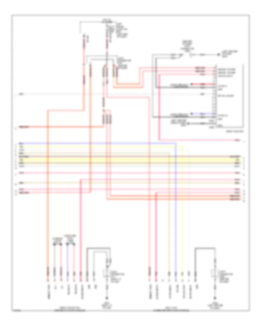 https://portal-diagnostov.com/license.html
Automotive Electricians Portal FZCO
Automotive Electricians Portal FZCO
https://portal-diagnostov.com/license.html
https://portal-diagnostov.com/license.html
Automotive Electricians Portal FZCO
Automotive Electricians Portal FZCOList of elements for Navigation Wiring Diagram (3 of 6) for Hyundai Equus Ultimate 2014:
- (center of dash) joint connector jm05
- (left center of dash) gm03
- (left center side of dash) gm03
- Acc/on input
- Computer data lines system
- Front dis switch (center of floor console)
- Front monitor
- Frt b/l on/off
- Gf07 (right "c" pillar)
- Gm03 (left center of dash)
- Gnd
- Hot at all times
- I/p-lhc
- I/p-lhg
- Ill +
- Ill -
- Interior lights system
- Joint connector jf11 (right "c" pillar)
- Joint connector jm05 (center of dash)
- Left smart junction box (left end of dash)
- Lh rr on/off
- M-can hi
- M-can lo
- M25g
- M25h
- Memory power
- Memory pwr
- Mf11
- Multi media fuse 15a
- Pnk
- Red
- Rh rr on/off
- Rr lock det
- Rr pnd
- Split unit (under center floor console)
Navigation Wiring Diagram (4 of 6) for Hyundai Equus Ultimate 2014
 https://portal-diagnostov.com/license.html
Automotive Electricians Portal FZCO
Automotive Electricians Portal FZCO
https://portal-diagnostov.com/license.html
https://portal-diagnostov.com/license.html
Automotive Electricians Portal FZCO
Automotive Electricians Portal FZCOList of elements for Navigation Wiring Diagram (4 of 6) for Hyundai Equus Ultimate 2014:
- Agnd
- Audio fuse 10a
- B-can
- B-can high
- B-can low
- Can hi
- Can lo
- Clockspring
- Computer data lines system
- Gf03 (left "c" pillar)
- Gm01 (left end of dash)
- Gnd
- Hot at all times
- Hot w/ pdm (acc) relay energized
- I/p-lhf
- I/p-rhd
- I/p-rhe
- Ill (+)
- Ill (-)
- Ips 3 (1ch)
- Ips 3 control
- Ips control module
- Joint connector jf01 (left "c" pillar)
- Joint connector jf11 (right "c" pillar)
- Joint connector jm01 (center of dash)
- Joint connector jm03 (right end of dash)
- Left smart junction box (left end of dash)
- Left steering wheel remote control switch (down)
- Left steering wheel remote control switch (up)
- M13
- M91
- M93-dl1
- M93-dl2
- Mem pwr
- Mf11
- Mf21
- Nca
- Pnk
- Power distribution system
- Red
- Right i/p junction box (right end of dash)
- Right steering wheel remote control switch (down)
- Right steering wheel remote control switch (up)
- Sig 1
- Sig 2
- Sig 3
- Steering wheel
Navigation Wiring Diagram (5 of 6) for Hyundai Equus Ultimate 2014
 https://portal-diagnostov.com/license.html
Automotive Electricians Portal FZCO
Automotive Electricians Portal FZCO
https://portal-diagnostov.com/license.html
https://portal-diagnostov.com/license.html
Automotive Electricians Portal FZCO
Automotive Electricians Portal FZCOList of elements for Navigation Wiring Diagram (5 of 6) for Hyundai Equus Ultimate 2014:
- (right "c" pillar) joint connector jf11
- Acc/on
- Alt
- Computer data lines system
- Dd31
- E-shifter fuse 10a
- Fd31
- Fd41
- Fs11
- Fs21
- Fs31
- Gf07 (right "c" pillar)
- Gnd
- Hot at all times
- Hot w/ pdm (acc) relay energized
- I/p-rhd
- I/p-rhe
- Ill (+)
- Ill (-)
- Interior lights system
- Left rear door middle speaker
- Left rear monitor
- Left rear tweeter speaker
- M-can hi
- M-can lo
- Mem pwr
- Memory power
- Mf21
- Nca
- Pnk
- Red
- Right i/p junction box (right end of dash)
- Right rear door middle speaker
- Right rear monitor
- Right rear tweeter speaker
- Ss31
- Starting/ charging system
- Usb charge fuse 10a
- Usb jack (6:4 seat)
Navigation Wiring Diagram (6 of 6) for Hyundai Equus Ultimate 2014
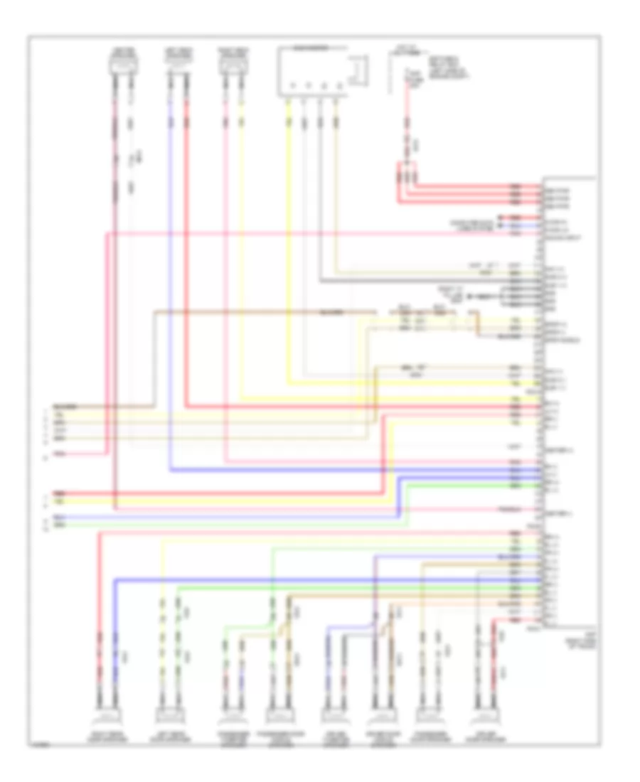 https://portal-diagnostov.com/license.html
Automotive Electricians Portal FZCO
Automotive Electricians Portal FZCO
https://portal-diagnostov.com/license.html
https://portal-diagnostov.com/license.html
Automotive Electricians Portal FZCO
Automotive Electricians Portal FZCOList of elements for Navigation Wiring Diagram (6 of 6) for Hyundai Equus Ultimate 2014:
- (+)
- (-)
- (right "c" pillar) gf07
- Acc/on input
- Amp (right side of trunk)
- Amp fuse 30a
- Center (+)
- Center (-)
- Center speaker
- Computer data lines system
- Dd11
- Dd21
- Driver door middle speaker
- Driver door speaker
- Driver tweeter speaker
- E/r fuse & relay box (left side of engine compt)
- Ef21
- F03-a
- F03-b
- F03-c
- Fd11
- Fd21
- Fd31
- Fd41
- Ff01
- Fl (+)
- Fl (-)
- Fr (+)
- Fr (-)
- Gnd
- Hot at all times
- Left deck speaker
- Left rear door speaker
- Lh (+)
- Lh (-)
- M-can hi
- M-can lo
- Mem pwr
- Mf21
- Navi (+)
- Navi (-)
- Nca
- Passenger door middle speaker
- Passenger door speaker
- Passenger tweeter speaker
- Pnk
- Red
- Rh (+)
- Rh (-)
- Right deck speaker
- Right rear door speaker
- Rl (+)
- Rl (-)
- Rr (+)
- Rr (-)
- Spdif (+)
- Spdif (-)
- Spdif shield
- Sub 1 (+)
- Sub 1 (-)
- Sub 2 (+)
- Sub 2 (-)
- Sub woofer
Parking Assistant Wiring Diagram (1 of 2) for Hyundai Equus Ultimate 2014
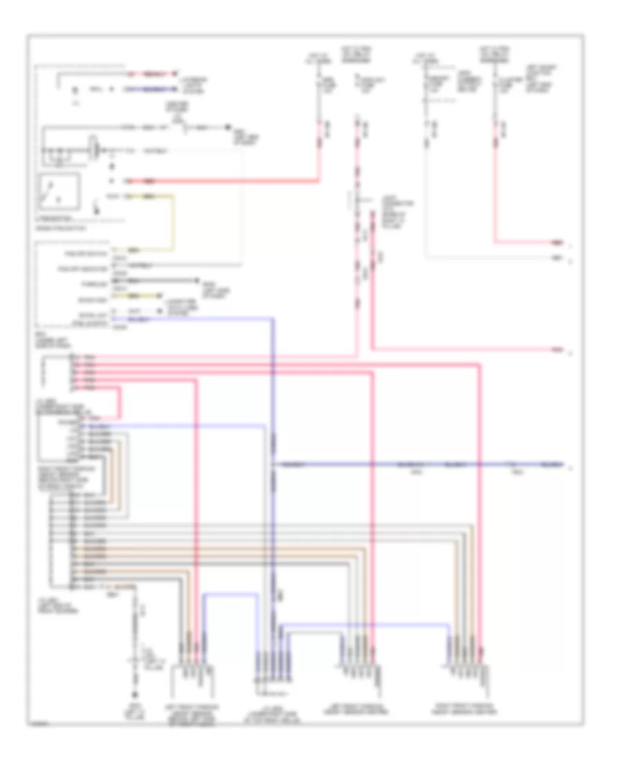 https://portal-diagnostov.com/license.html
Automotive Electricians Portal FZCO
Automotive Electricians Portal FZCO
https://portal-diagnostov.com/license.html
https://portal-diagnostov.com/license.html
Automotive Electricians Portal FZCO
Automotive Electricians Portal FZCOList of elements for Parking Assistant Wiring Diagram (1 of 2) for Hyundai Equus Ultimate 2014:
- (center of dash) j/c jm05
- B-can high
- B-can low
- Bcm (under left side of dash)
- Cluster fuse 10a
- Computer data lines system
- Crash pad switch
- Ee41
- Ef11
- Em31
- Epb fuse 10a
- Fr31
- Gf03 (left "c" pillar)
- Gm01 (left end of dash)
- Gm05 (left side of dash)
- Gnd
- Hot at all times
- Hot w/ pdm (ig1) relay energized
- I/p-lhc
- I/p-lhf
- I/p-lhg
- Ill
- Interior lights system
- J/c je21 (left end of front bumper)
- J/c je22 (under right side of top front grille)
- J/c jf01 (left "c" pillar)
- Joint connector jf12 (base of right "c" pillar)
- Leak current autocut device
- Left front parking assist sensor (behind left side of front fascia)
- Left front parking assist sensor (center)
- Left smart junction box (left end of dash)
- Lid1
- Lid2
- Lid3
- Lin
- Logic
- M32-a
- M32-b
- Memory fuse 10a
- Mf21
- Module 3 fuse 10a
- P-ground
- Pas lin data
- Pas off indicator
- Pas off switch
- Pas switch
- Pnk
- Power
- Red
- Right front parking assist sensor (behind right side of front fascia)
- Right front parking assist sensor (center)
Parking Assistant Wiring Diagram (2 of 2) for Hyundai Equus Ultimate 2014
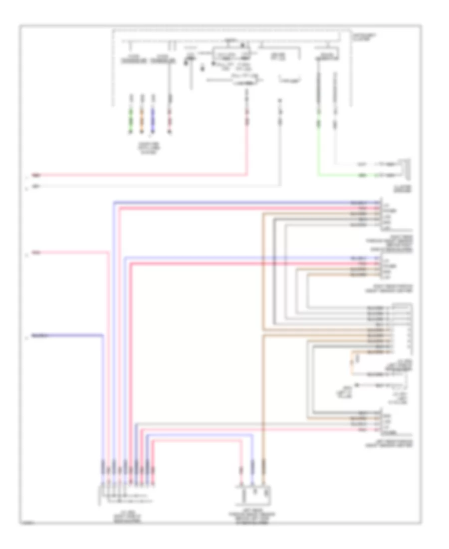 https://portal-diagnostov.com/license.html
Automotive Electricians Portal FZCO
Automotive Electricians Portal FZCO
https://portal-diagnostov.com/license.html
https://portal-diagnostov.com/license.html
Automotive Electricians Portal FZCO
Automotive Electricians Portal FZCOList of elements for Parking Assistant Wiring Diagram (2 of 2) for Hyundai Equus Ultimate 2014:
- (7 inch tft lcd)
- (full tft lcd)
- 1.2v reg
- 1.5v/1.275v reg
- 1.8v reg
- 3.3v reg
- C-can transceiver
- Cluster speaker
- Computer data lines system
- Driver tft lcd
- Fr31
- Gf03 (left "c" pillar)
- Gnd
- High
- Instrument cluster
- J/c jf01 (left "c" pillar)
- J/c jr22 (left side of rear bumper)
- J/c jr23 (right side of rear bumper)
- Left rear parking assist sensor (behind left side of rear bumper)
- Left rear parking assist sensor (center)
- Lid1
- Lid2
- Lin
- Low
- M-can transceiver
- Micom
- Nca
- Pnk
- Power
- Red
- Right rear parking assist sensor (behind right side of rear bumper)
- Right rear parking assist sensor (center)
- Sound generator
- Speaker out (+)
- Speaker out (-)
- Tft lcd
Rear Camera Wiring Diagram for Hyundai Equus Ultimate 2014
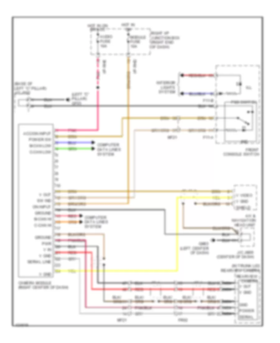 https://portal-diagnostov.com/license.html
Automotive Electricians Portal FZCO
Automotive Electricians Portal FZCO
https://portal-diagnostov.com/license.html
https://portal-diagnostov.com/license.html
Automotive Electricians Portal FZCO
Automotive Electricians Portal FZCOList of elements for Rear Camera Wiring Diagram for Hyundai Equus Ultimate 2014:
- (base of left "c" pillar) j/c jf02
- (in trunk lid) rearview camera
- (left "c" pillar) gf03
- A/v & navigation head unit
- Acc/on input
- Audio fuse 10a
- C-can hi
- C-can low
- Camera module (right center of dash)
- Computer data lines system
- F11-a
- F11-b
- Fr02
- Front console switch
- Gm03 (left center of dash)
- Gnd
- Ground
- Hot in on
- Hot in on or acc
- I/p-rhd
- I/p-rhe
- Ill
- Ind
- Interior lights system
- J/c jm05 (center of dash)
- M-can hi
- M-can low
- Mf21
- Module fuse 10a
- Nca
- On input
- Pgs switch
- Pnk
- Power
- Power sw
- Pwr
- Rearview camera
- Red
- Right i/p junction box (right end of dash)
- Serial
- Serial line
- Shield
- Sw ind
- V gnd
- V in
- V out
- V video
POWER DISTRIBUTION
Power Distribution Wiring Diagram (1 of 13) for Hyundai Equus Ultimate 2014
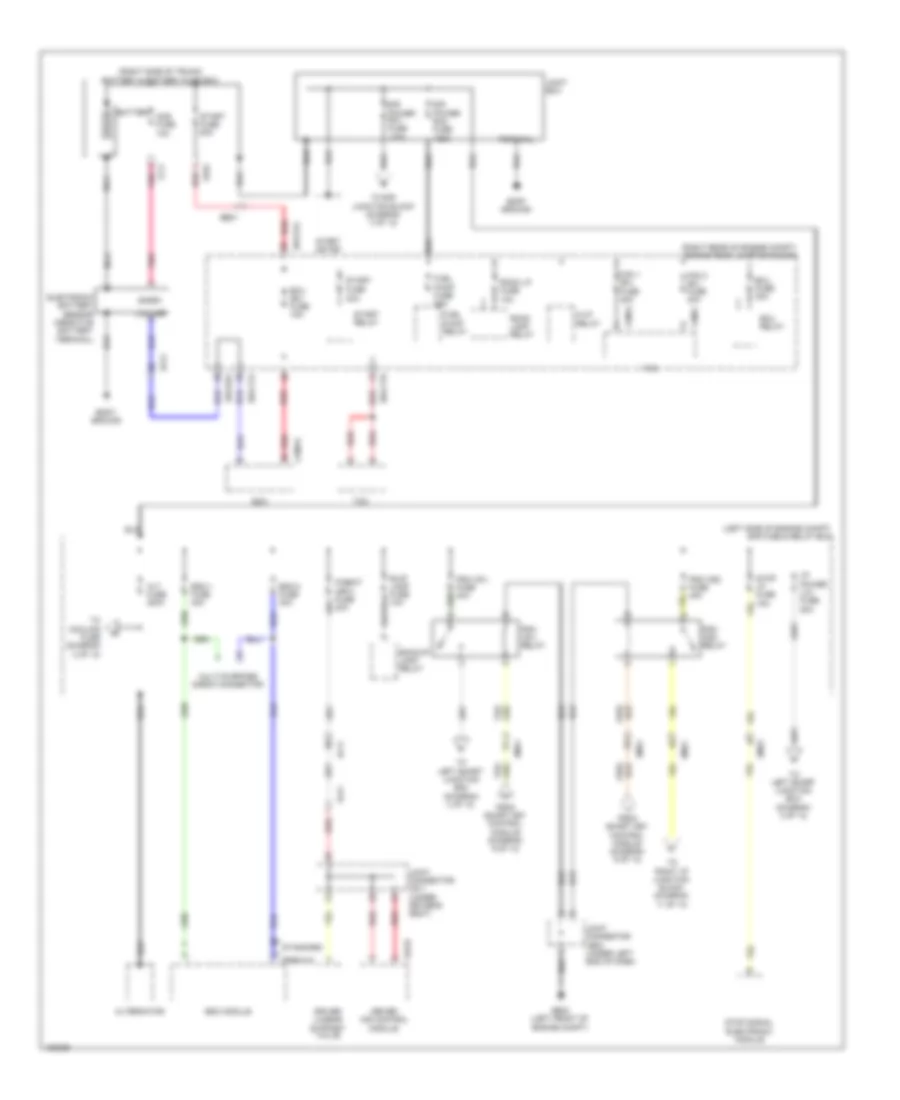 https://portal-diagnostov.com/license.html
Automotive Electricians Portal FZCO
Automotive Electricians Portal FZCO
https://portal-diagnostov.com/license.html
https://portal-diagnostov.com/license.html
Automotive Electricians Portal FZCO
Automotive Electricians Portal FZCOList of elements for Power Distribution Wiring Diagram (1 of 13) for Hyundai Equus Ultimate 2014:
- (left side of engine compt) e/r fuse & relay box
- (right rear of engine compt) engine room junction block
- (right side of trunk) battery & battery fuse box
- Alt fuse 200a
- Alternator
- Ams fuse 10a
- B/up lamp fuse 10a
- Backup lamp relay
- Battery
- Body ground
- C200-k
- Driver ims control module
- Driver lumbar support valve
- E/r power rh1 fuse 125a
- E/r power rh2 fuse 125a
- E/r-cta
- E/r-ctb
- E/r-e1a
- E/r-e2a
- Ecm
- Ecu (b+) fuse 15a
- Ecu fuse 30a
- Ecu relay
- Ee01
- Ef01
- Ef11
- Ef21
- Em21
- Em31
- Em41
- Esc module
- Esc-1 fuse 40a
- Esc-2 fuse 40a
- Fam
- Fam 1 (b+)
- Fam 2 (b+) fuse 40a
- Fam-a
- Fam-c
- Ff11
- From smart key control module (diagram 9 of 13)
- Fs11
- Fuel pump fuse 20a
- Fuel pump relay
- Fuse 30a
- Fuse 40a
- Ge03 (left front of engine compt)
- H/lp relay
- I/p power (lh) fuse 80a
- Joint box
- Joint connector je02 (under left end of dash)
- Joint connector js11 (under driver's seat)
- Lin line
- Multi-purpose check connector
- Nca
- P/seat (drv) fuse 30a
- Pdm (ig1) fuse 40a
- Pdm (ig1) relay
- Pdm (ig2) fuse 40a
- Pdm (ig2) relay
- Pnk
- Premium
- Red
- Room lamp relay
- Room lp fuse 10a
- S16-b
- Snsr+
- Standard
- Start
- Start fuse 50a
- Start motor
- Start relay
- Stop lp fuse 15a
- Stop signal electronic module
- Tcm
- Terminal
- To cooling fuse (diagram 2 of 13)
- To e/r junction block (diagram 3 of 13)
- To left smart junction box (diagram 3 of 13)
- To left smart junction box (diagram 4 of 13)
- To right i/p junction block (diagram 11 of 13)
Power Distribution Wiring Diagram (2 of 13) for Hyundai Equus Ultimate 2014
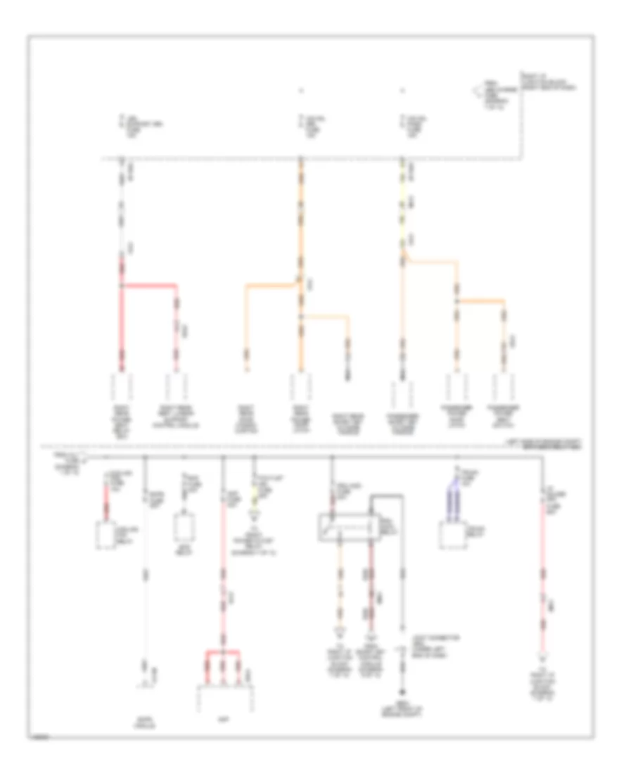 https://portal-diagnostov.com/license.html
Automotive Electricians Portal FZCO
Automotive Electricians Portal FZCO
https://portal-diagnostov.com/license.html
https://portal-diagnostov.com/license.html
Automotive Electricians Portal FZCO
Automotive Electricians Portal FZCOList of elements for Power Distribution Wiring Diagram (2 of 13) for Hyundai Equus Ultimate 2014:
- (diagram 1 of 13)
- (left side of engine compt) e/r fuse & relay box
- Amp
- Amp fuse 30a
- Cooling fan fuse 70a
- Cooling fan relay
- Dd21
- E11-m
- Ecs fuse 40a
- Ecs relay
- Ef21
- Ehps fuse 80a
- Ehps module
- Em11
- Em41
- F03-a
- Fd21
- Fd41
- From alt fuse c
- From smart key control module (diagram 9 of 13)
- From usb charge fuse (diagram 7 of 13)
- Fs41
- Fuse 60a
- Ge03 (left front of engine compt)
- I/p power (rh)
- I/p-rha
- I/p-rhe
- Joint connector je02 (under left end of dash)
- Leg support (rr) fuse 15a
- Mf21
- Nca
- O/s hdl (rr) fuse 15a
- O/s hdl pass fuse 15a
- P/outlet (fr) fuse 25a
- Passenger power door latch
- Passenger power seat switch
- Passenger smart key outside handle
- Pdm (acc) fuse 30a
- Pdm (acc) relay
- Red
- Right i/p junction block (right end of dash)
- Right rear door window curtain
- Right rear power door latch
- Right rear power seat relay box
- Right rear seat lumbar support control module
- Right rear smart key outside handle
- Ss42
- To front power outlet relay (diagram 7 of 13)
- To right i/p junction block (diagram 7 of 13)
- Trunk fuse 10a
- Trunk relay
Power Distribution Wiring Diagram (3 of 13) for Hyundai Equus Ultimate 2014
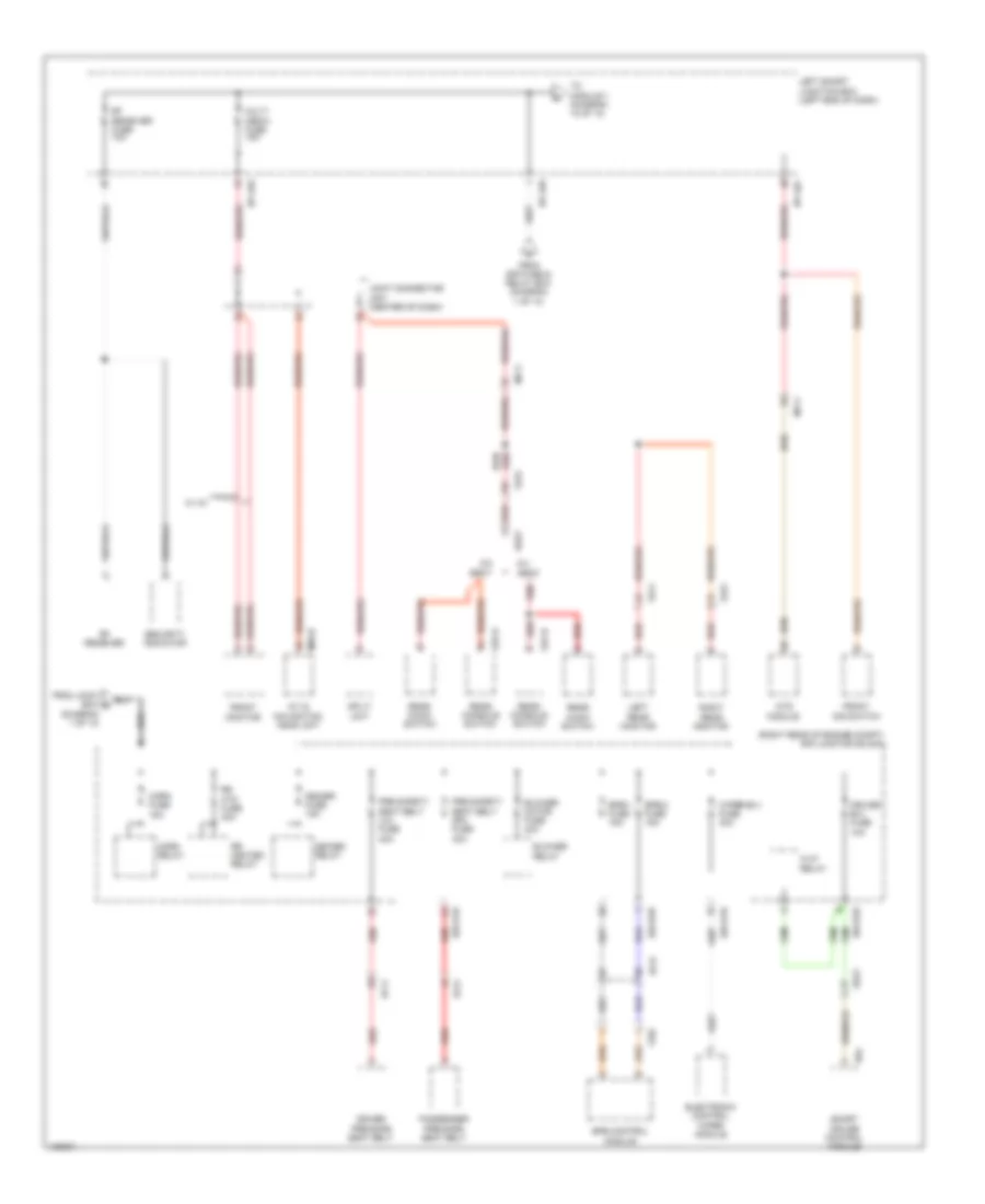 https://portal-diagnostov.com/license.html
Automotive Electricians Portal FZCO
Automotive Electricians Portal FZCO
https://portal-diagnostov.com/license.html
https://portal-diagnostov.com/license.html
Automotive Electricians Portal FZCO
Automotive Electricians Portal FZCOList of elements for Power Distribution Wiring Diagram (3 of 13) for Hyundai Equus Ultimate 2014:
- (diagram 1 of 13)
- (right rear of engine compt) e/r junction block
- 5:5 seat
- 6:4 seat
- A/v & navigation head unit
- Blower motor fuse 40a
- Blower relay
- Cruise b(+) fuse 10a
- Deicer fuse 15a
- Deicer relay
- Driver pre-safe seat belt
- E/r-e1b
- E/r-e2b
- E64
- Ee21
- Ef11
- Ef21
- Ef31
- Electronic control wiper module
- Epb control module
- Epb-1 fuse 15a
- Epb-2 fuse 15a
- Ff02
- From e/r fuse & relay box (diagram 1 of 13)
- From joint box b
- Front dis switch
- Front monitor
- Fs11
- Fs21
- Fs31
- H/lp relay
- Horn fuse 15a
- Horn relay
- I/p-lhc
- I/p-lhd
- I/p-lhg
- Joint connector jm01 (center of dash)
- Left rear monitor
- Left smart junction box (left end of dash)
- M03-b
- Mf11
- Mts module
- Multi media fuse 15a
- Passenger pre-safe seat belt
- Pre safety seat belt (lh) fuse 40a
- Pre safety seat belt (rh) fuse 40a
- Rear audio switch
- Rear console switch
- Red
- Rf receiver
- Rf receiver fuse 10a
- Right rear monitor
- Rr heated relay
- Rr htd fuse 40a
- S27-b
- S37-b
- Security indicator
- Smart cruise control module
- Split unit
- Ss31
- To module 1 (diagram 12 of 13)
- W/ av
- Wiper b(+) fuse 30a
Power Distribution Wiring Diagram (4 of 13) for Hyundai Equus Ultimate 2014
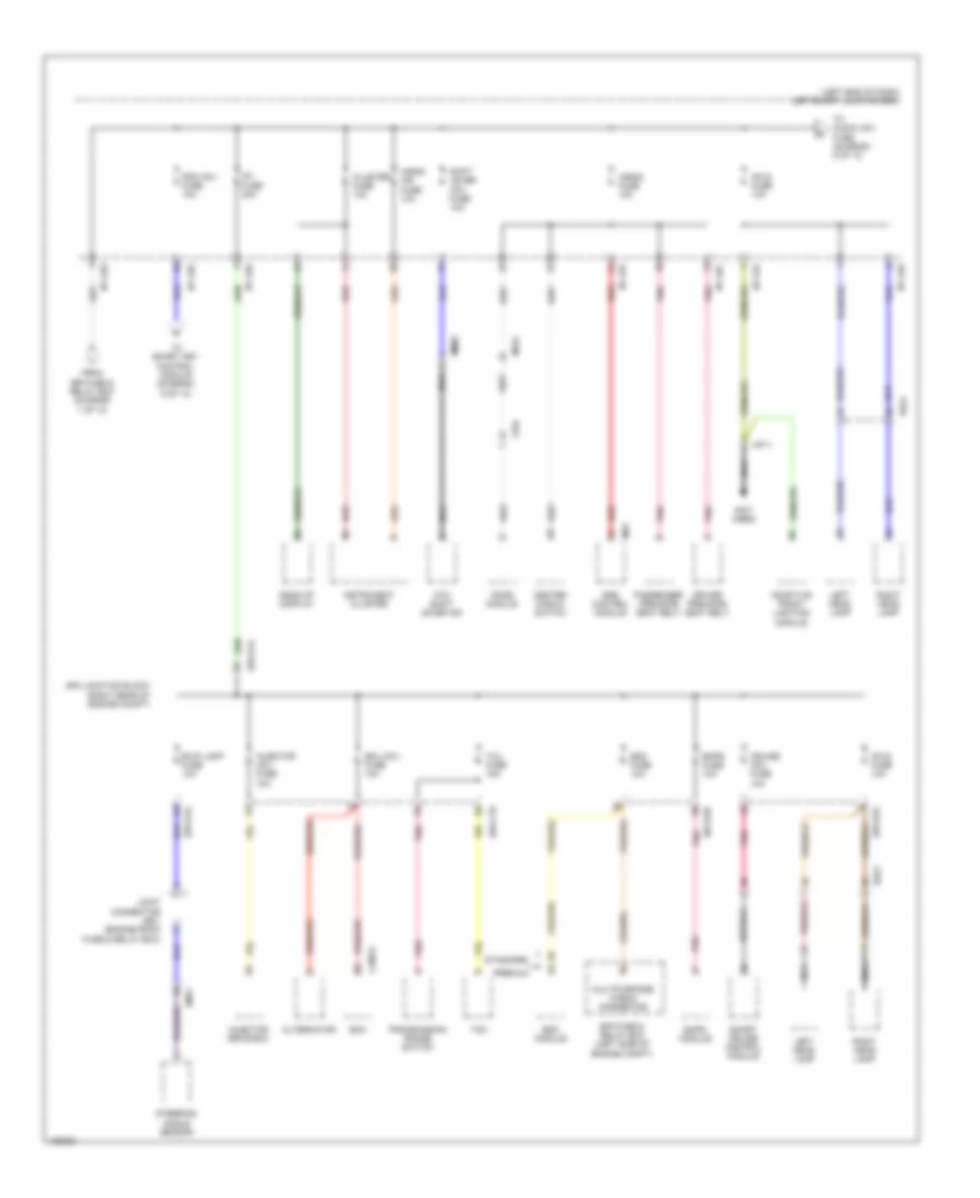 https://portal-diagnostov.com/license.html
Automotive Electricians Portal FZCO
Automotive Electricians Portal FZCO
https://portal-diagnostov.com/license.html
https://portal-diagnostov.com/license.html
Automotive Electricians Portal FZCO
Automotive Electricians Portal FZCOList of elements for Power Distribution Wiring Diagram (4 of 13) for Hyundai Equus Ultimate 2014:
- (left end of dash) left smart junction box
- (not used)
- A/bag fuse 15a
- A/bag ind fuse 10a
- Adaptive front lighting module
- Afls fuse 10a
- Alternator
- Atm shift lever ind
- B/up lamp fuse 10a
- C200-k
- Center fascia switch
- Cluster fuse 10a
- Cruise (ig1) fuse 10a
- Driver pre-safe seat belt
- E/r fuse & relay box (left side of engine compt)
- E/r junction block (right rear of engine compt)
- E/r-ctb
- E/r-e1a
- E/r-e2a
- E/r-e2b
- Ecm
- Ecu (ig1) fuse 10a
- Ee21
- Ehps fuse 10a
- Ehps module
- Em41
- Esc fuse 10a
- Esc module
- Ff04
- From e/r fuse & relay box (diagram 1 of 13)
- Head-up display
- I/p-lhc
- I/p-lhe
- I/p-lhf
- I/p-lhg
- Ig1 fuse 30a
- Injector (ig1) fuse 10a
- Injector drive box
- Instrument cluster
- Joint connector je01 (engine room fuse & relay box)
- Left head lamp
- M53
- Mf01
- Mf11
- Mm02
- Multipurpose check connector
- Nca
- Passenger pre-safe seat belt
- Pdm (ig1) fuse 10a
- Pnk
- Pods module
- Premium
- Red
- Right head lamp
- Shift lever (ig1) fuse 10a
- Smart cruise control module
- Srs control module
- Standard
- Steering angle sensor
- Tcm
- Tcu fuse 15a
- To audio (ig1) fuse (diagram 5 of 13)
- To smart key control module (diagram 9 of 13)
- Transmission range switch
Power Distribution Wiring Diagram (5 of 13) for Hyundai Equus Ultimate 2014
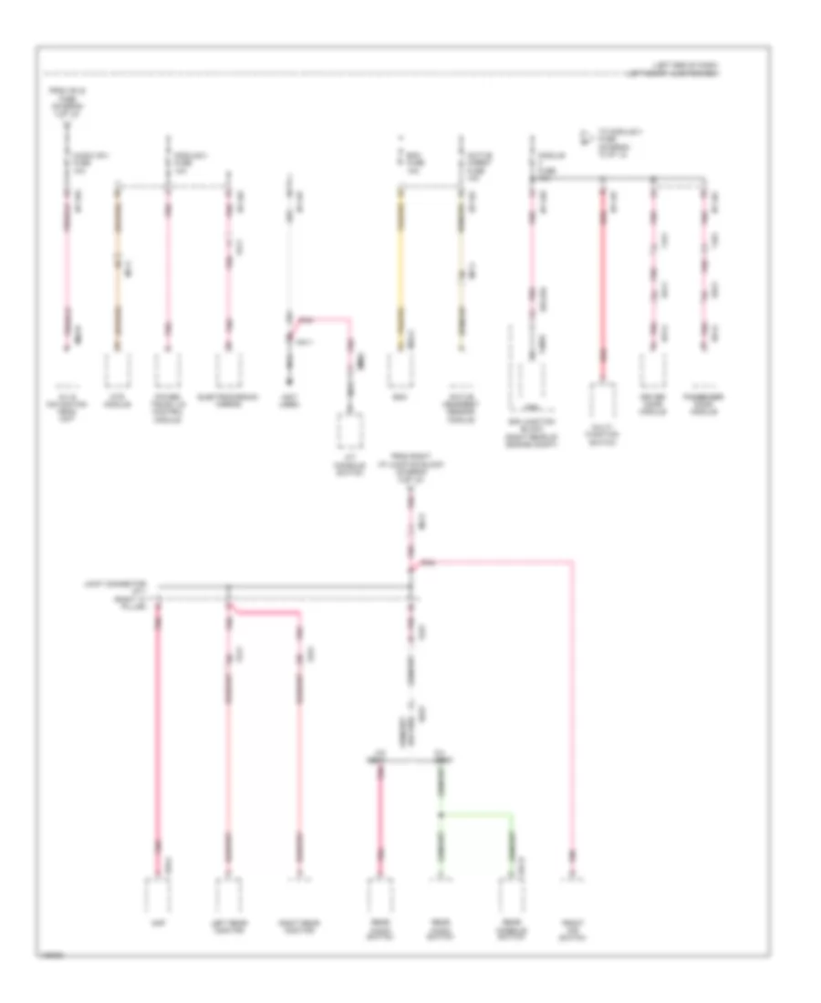 https://portal-diagnostov.com/license.html
Automotive Electricians Portal FZCO
Automotive Electricians Portal FZCO
https://portal-diagnostov.com/license.html
https://portal-diagnostov.com/license.html
Automotive Electricians Portal FZCO
Automotive Electricians Portal FZCOList of elements for Power Distribution Wiring Diagram (5 of 13) for Hyundai Equus Ultimate 2014:
- (left end of dash) left smart junction box
- (not used)
- 5:5 seat
- 6:4 seat
- A/t console switch
- A/v & navigation head unit
- Active h/rest fuse 10a
- Active headrest sensor module
- Amp
- Audio (ig1) fuse 10a
- Bcm
- Bcm fuse 10a
- D51-c
- D61-c
- Dd11
- Dd21
- Driver door module
- E/r junction block (right rear of engine compt)
- E/r-e1b
- Electrochromic mirror
- F03-a
- Fam
- Fam-b
- Fd11
- Fd21
- Fr11
- From afls fuse (diagram 4 of 13)
- From right i/p junction block (diagram 8 of 13)
- Front dis switch
- Fs11
- Fs21
- Fs31
- I/p-lhc
- I/p-lhe
- I/p-lhf
- I/p-lhg
- Joint connector jf11 (right "c" pillar)
- Left rear monitor
- M03-b
- M32-a
- Mf11
- Mf21
- Mm02
- Mm11
- Module 2 fuse 10a
- Module fuse 10a
- Mts module
- Multi- function switch
- Nca
- Passenger door module
- Pnk
- Power trunk lid control module
- Rear audio switch
- Rear console switch
- Red
- Right rear monitor
- S27-b
- Ss31
- To module 3 fuse (diagram 10 of 13)
Power Distribution Wiring Diagram (6 of 13) for Hyundai Equus Ultimate 2014
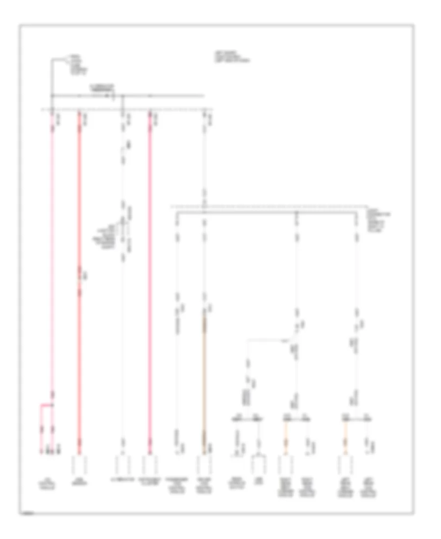 https://portal-diagnostov.com/license.html
Automotive Electricians Portal FZCO
Automotive Electricians Portal FZCO
https://portal-diagnostov.com/license.html
https://portal-diagnostov.com/license.html
Automotive Electricians Portal FZCO
Automotive Electricians Portal FZCOList of elements for Power Distribution Wiring Diagram (6 of 13) for Hyundai Equus Ultimate 2014:
- 5:5 seat
- 6:4 seat
- A/c control module
- Alternator
- Alternator resistor
- Aqs sensor
- Driver ccs control module
- E/r junction block (right rear of engine compt)
- E/r-cta
- E/r-e2a
- Ee21
- Em21
- From a/con j
- Fs11
- Fs21
- Fs31
- Fs41
- Fuse (diagram 10 of 13)
- I/p-lhc
- I/p-lhe
- I/p-lhf
- I/p-lhg
- Instrument cluster
- Joint connector jf12 (base of right "c" pillar)
- Left rear ccs control module
- Left rear seat warmer module
- Left smart junction box (left end of dash)
- M07-b
- M07-c
- Passenger ccs control module
- Pnk
- Rear console switch
- Red
- Right rear ccs control module
- Right rear seat warmer module
- S06-b
- S106-b
- S146-b
- S37-b
- S46-b
- Ss41
- Usb jack
- W/ ccs
- W/o ccs
Power Distribution Wiring Diagram (7 of 13) for Hyundai Equus Ultimate 2014
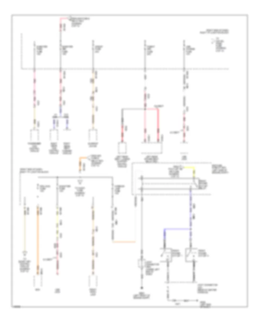 https://portal-diagnostov.com/license.html
Automotive Electricians Portal FZCO
Automotive Electricians Portal FZCO
https://portal-diagnostov.com/license.html
https://portal-diagnostov.com/license.html
Automotive Electricians Portal FZCO
Automotive Electricians Portal FZCOList of elements for Power Distribution Wiring Diagram (7 of 13) for Hyundai Equus Ultimate 2014:
- (left end of dash)
- (right end of dash) right i/p junction block
- 5:5 seat
- 6:4 seat
- Bcm
- E-shifter fuse 10a
- E/r fuse & relay box (left side of engine compt)
- Em31
- Em41
- Fr21
- From e/r fuse & relay box (diagram 2 of 13)
- From p/outlet (fr) fuse (diagram 2 of 13)
- Front power outlet 1
- Front power outlet 2
- Front power outlet relay
- Front room lamp
- Fs21
- Fs31
- Fs41
- Ge03 (left front of engine compt)
- Gm06
- I/p-rha
- I/p-rhb
- I/p-rhc
- I/p-rhd
- I/p-rhe
- Interior lamp fuse 10a
- Joint connector je02 (under left end of dash)
- Joint connector jm21 (rear of center console)
- Left rear power seat relay box
- Left rear seat lumbar support control module
- M32-a
- Mf21
- Mm11
- Nca
- P/seat (rr) fuse 20a
- Passenger ccs control module
- Pdm (acc) fuse 10a
- Pnk
- Red
- Right rear ccs control module
- Right rear seat warmer module
- S/heater (rr) fuse 15a
- S/heater pass fuse 15a
- S/roof fuse 20a
- S126-1
- S126-2
- S146-a
- S46-a
- Ss31
- Ss32
- Sunroof motor
- To audio fuse (diagram 8 of 13)
- To o/s hdl pass fuse (diagram 2 of 13)
- To smart key control module (diagram 9 of 13)
- Usb charge fuse 10a
- Usb jack
- W/ ccs
- W/o ccs
Power Distribution Wiring Diagram (8 of 13) for Hyundai Equus Ultimate 2014
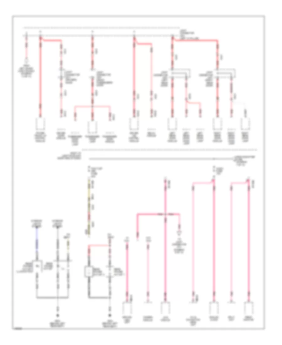 https://portal-diagnostov.com/license.html
Automotive Electricians Portal FZCO
Automotive Electricians Portal FZCO
https://portal-diagnostov.com/license.html
https://portal-diagnostov.com/license.html
Automotive Electricians Portal FZCO
Automotive Electricians Portal FZCOList of elements for Power Distribution Wiring Diagram (8 of 13) for Hyundai Equus Ultimate 2014:
- 5:5 seat
- 6:4 seat
- A/v & navigation head unit
- Analog clock
- Around view unit
- Audio fuse 10a
- Camera module
- D51-c
- D61-c
- Dd11
- Dd21
- Dd31
- Dd41
- Driver door module
- Driver ims control module
- Fd11
- Fd21
- Fd31
- Fd41
- From e-shifter fuse (diagram 7 of 13)
- From left smart junction box (diagram 13 of 13)
- Front monitor
- Fs11
- Fs21
- Fs31
- Gf04 (behind left rear seat)
- I/p-rhb
- I/p-rhd
- I/p-rhe
- Ill
- Interior lights system
- Joint connector jd11 (driver's door)
- Joint connector jd21 (front passenger's door)
- Joint connector jd31 (left rear door)
- Joint connector jd41 (right rear door)
- Joint connector jf01 (left "c" pillar)
- Left rear door lamp
- Left rear door module
- Left rear door mood lamp
- M03-b
- M04-b
- Mf21
- Mts module
- Nca
- P/outlet (rr) fuse 20a
- Passenger door lamp
- Passenger door module
- Passenger door mood lamp
- Pnk
- Power trunk lid control module
- Rear power outlet
- Rear power outlet 1
- Rear power outlet 2
- Rear power outlet illumination
- Red
- Relax module
- Right i/p junction block (right end of dash)
- Right rear door lamp
- Right rear door module
- Right rear door mood lamp
- S16-d
- S70-d
- Split unit
- Ss31
- To joint connector jf11 (diagram 5 of 13)
- W/ avm
- W/o avm
Power Distribution Wiring Diagram (9 of 13) for Hyundai Equus Ultimate 2014
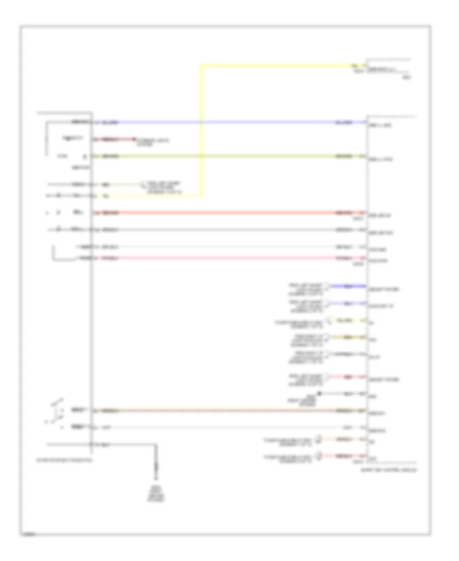 https://portal-diagnostov.com/license.html
Automotive Electricians Portal FZCO
Automotive Electricians Portal FZCO
https://portal-diagnostov.com/license.html
https://portal-diagnostov.com/license.html
Automotive Electricians Portal FZCO
Automotive Electricians Portal FZCOList of elements for Power Distribution Wiring Diagram (9 of 13) for Hyundai Equus Ultimate 2014:
- Acc
- Bcm
- From left smart i junction box (diagram 13 of 13)
- From left smart junction box (diagram 13 of 13)
- From left smart junction box (diagram 4 of 13)
- From left smart u junction box (diagram 13 of 13)
- From right i/p junction block (diagram 11 of 13)
- From right i/p junction block (diagram 7 of 13)
- Gm04 (right center of dash)
- Gnd
- Ig1
- Ig2
- Ill
- Immo gnd
- Immo pwr
- Interior lights system
- M30-a
- M30-b
- M30-c
- M32-c
- Memory power
- On i/p
- On/start i/p
- Pwr
- Red
- Rheostat
- Sbb ill gnd
- Sbb pwr
- Smart key control module
- Ssb b+
- Ssb gnd
- Ssb ill pwr
- Ssb led acc
- Ssb led on
- Ssb ring ill(-)
- Ssb sw 1
- Ssb sw 2
- Ssb sw1
- Ssb sw2
- Start/stop button switch
- To e/r fuse & relay box (diagram 1 of 13)
- To e/r fuse & relay box (diagram 2 of 13)
Power Distribution Wiring Diagram (10 of 13) for Hyundai Equus Ultimate 2014
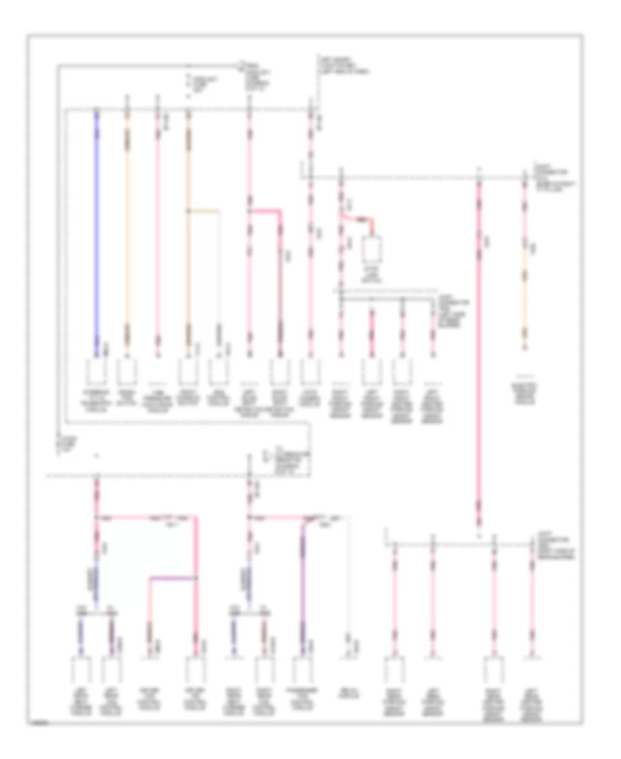 https://portal-diagnostov.com/license.html
Automotive Electricians Portal FZCO
Automotive Electricians Portal FZCO
https://portal-diagnostov.com/license.html
https://portal-diagnostov.com/license.html
Automotive Electricians Portal FZCO
Automotive Electricians Portal FZCOList of elements for Power Distribution Wiring Diagram (10 of 13) for Hyundai Equus Ultimate 2014:
- A/con fuse 10a
- Crash pad switch
- Driver ccs control module
- Driver ims control module
- Ecs control module
- Ee41
- Ef11
- Electric parking brake module
- F01-a
- F11-a
- Ff02
- Fr21
- Fr31
- From module 4 fuse (diagram 5 of 13)
- Front console switch
- Fs11
- Fs21
- Fs31
- Fs41
- I/p-lhc
- I/p-lhg
- Joint connector jf12 (base of right "c" pillar)
- Joint connector jr22 (left side of rear bumper)
- Joint connector jr23 (right side of rear bumper)
- Ldws camera module
- Left blind spot detection radar
- Left front center parking assist sensor
- Left front parking assist sensor
- Left rear ccs control module
- Left rear center parking assist sensor
- Left rear parking assist sensor
- Left rear seat warmer module
- Left smart junction box (left end of dash)
- M52-a
- Module 3 fuse 30a
- Passenger ccs control module
- Pnk
- Red
- Relax module
- Right blind spot detection radar
- Right front center parking assist sensor
- Right front parking assist sensor
- Right rear ccs control module
- Right rear center parking assist sensor
- Right rear parking assist sensor
- Right rear seat warmer module
- S06-b
- S106-b
- S146-b
- S16-d
- S46-b
- S70-d
- Steering tilt & telescopic module
- Stop lamp switch
- Tire pressure monitoring module
- To alternator resistor (diagram 6 of 13)
- W/ ccs
- W/o ccs
Power Distribution Wiring Diagram (11 of 13) for Hyundai Equus Ultimate 2014
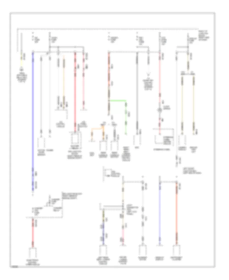 https://portal-diagnostov.com/license.html
Automotive Electricians Portal FZCO
Automotive Electricians Portal FZCO
https://portal-diagnostov.com/license.html
https://portal-diagnostov.com/license.html
Automotive Electricians Portal FZCO
Automotive Electricians Portal FZCOList of elements for Power Distribution Wiring Diagram (11 of 13) for Hyundai Equus Ultimate 2014:
- 5:5 seat
- 6:4 seat
- A/c control module
- A/con fuse 10a
- Active incar sensor
- Around view unit
- Bcm
- Blower relay
- Camera module
- Clock spring
- Cool box
- Driver lumbar support valve
- E/r junction block (right rear of engine compt)
- E/r-e1b
- E/r-e2b
- Electronic control wiper module
- Em21
- Em41
- Fr11
- From e/r fuse & relay box (diagram 1 of 13)
- Fs11
- Fs31
- Fs41
- Head-up display
- Htd strg fuse 15a
- I/p-lhb
- I/p-lhg
- I/p-rha
- I/p-rhb
- I/p-rhd
- Ice box fuse 15a
- Ig2
- Ig2 fuse 30a
- Instrument cluster
- Ionizer
- Ips control module
- Joint connector jf03 (left kick panel)
- Lcd panel switch
- Left rear seat lumbar control module
- Left smart junction box (left end of dash)
- M04-b
- M07-b
- M07-c
- M13
- M32-a
- M91
- Mf21
- Mm11
- Module fuse 10a
- Pdm (ig2) fuse 10a
- Rear console switch
- Red
- Right i/p junction block (right end of dash)
- Right rear seat lumbar support control module
- S27-b
- S37-b
- Ss32
- Ss41
- Ss42
- Steering wheel
- Steering wheel heated module
- Sunroof motor
- To smart key control module (diagram 9 of 13)
- W/ avm
- W/o avm
- Washer (ig2) fuse 10a
- Washer fuse 15a
- Washer relay
Power Distribution Wiring Diagram (12 of 13) for Hyundai Equus Ultimate 2014
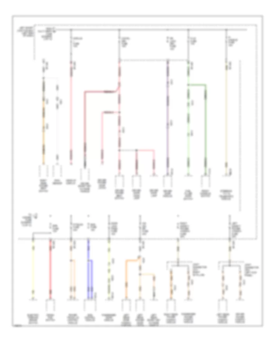 https://portal-diagnostov.com/license.html
Automotive Electricians Portal FZCO
Automotive Electricians Portal FZCO
https://portal-diagnostov.com/license.html
https://portal-diagnostov.com/license.html
Automotive Electricians Portal FZCO
Automotive Electricians Portal FZCOList of elements for Power Distribution Wiring Diagram (12 of 13) for Hyundai Equus Ultimate 2014:
- Crash pad switch
- D51-a
- D61-a
- Dd11
- Dd21
- Dd41
- Door lock pass fuse 15a
- Dr lock drv fuse 10a
- Driver door lamp
- Driver door module
- Driver door mood lamp
- Driver power door latch
- Driver power seat switch
- Driver power window module
- Driver smart key outside handle
- Ecs control module
- Ecs fuse 15a
- Electric parking brake switch
- Epb fuse 10a
- F/lid fuse 10a
- F01-a
- F11-a
- Fd11
- Fd21
- Fd31
- Fd41
- Fr21
- From multi media g
- Front console switch
- Fuel filler door switch
- Fuse (diagram 3 of 13)
- Head-up display
- I/p-lha
- I/p-lhc
- I/p-lhg
- Joint connector jf03 (left kick panel)
- Joint connector jf13 (right "b" pillar)
- Left rear door window curtain
- Left rear power door latch
- Left rear power window module
- Left rear smart key outside handle
- Left safety power window fuse 30a
- Left smart junction box (left end of dash)
- M52-b
- Module fuse 10a
- Nca
- O/s hdl drv fuse 15a
- O/s hdl rr fuse 30a
- P/ handle fuse 15a
- P/trunk fuse 30a
- Passenger door module
- Passenger power window module
- Power trunk lid control module
- Rain sensor
- Red
- Right rear power seat switch
- Right rear power window module
- Right safety power window fuse 30a
- Steering tilt & telescopic module
- To hazard fuse (diagram 13 of 13)
Power Distribution Wiring Diagram (13 of 13) for Hyundai Equus Ultimate 2014
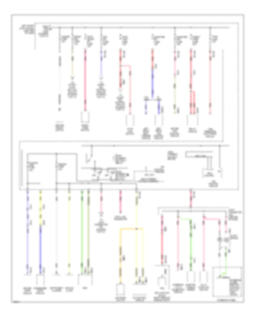 https://portal-diagnostov.com/license.html
Automotive Electricians Portal FZCO
Automotive Electricians Portal FZCO
https://portal-diagnostov.com/license.html
https://portal-diagnostov.com/license.html
Automotive Electricians Portal FZCO
Automotive Electricians Portal FZCOList of elements for Power Distribution Wiring Diagram (13 of 13) for Hyundai Equus Ultimate 2014:
- A/c control module
- Analog clock
- Bcm
- Center fascia switch
- Clock spring
- D51-a
- D61-a
- Data link connector
- Dd11
- Dd21
- Driver ccs control module
- Driver door module
- E/r junction block (right rear of engine compt)
- E/r-e1b
- Electro- chromic mirror
- Em21
- Em31
- Fam
- Fam-b
- Fd11
- Fd21
- Folding mirr fuse 10a
- Fr11
- From epb q
- Fs11
- Fs21
- Fs31
- Fuse (diagram 12 of 13)
- Hazard fuse 10a
- I/p-lha
- I/p-lhc
- I/p-lhe
- I/p-lhf
- I/p-lhg
- Instrument cluster
- Ips 3 (1ch)
- Ips 3 control
- Ips control module
- Joint connector jm01 (center of dash)
- Lcd panel switch
- Leak current autocut control
- Leak current autocut device
- Leak current autocut relay
- Leak current autocut switch
- Left rear ccs control module
- Left rear seat warmer module
- Left smart junction box (left end of dash)
- M07-b
- M07-c
- M13
- M32-a
- M32-c
- M52-a
- M91
- M93-dl1
- Memory fuse 10a
- Mf11
- Mm11
- Multi- function switch
- Off
- P/seat pass fuse 30a
- Passenger door module
- Pdm (b+) fuse 25a
- Pnk
- Red
- Relax module
- Rly
- S/heater drv fuse 15a
- S/heater rr fuse 15a
- S06-a
- S106-a
- S70-b
- Shift lever (b+) fuse 10a
- Smart key fuse 10a
- Sport mode switch
- Steering tilt & telescopic module
- Steering wheel
- Steering wheel remote control switch (left down)
- Stop lamp fuse 10a
- Stop lamp switch
- Tire pressure monitoring module
- To joint connector jf01 (diagram 8 of 13)
- To smart key control module (diagram 9 of 13)
- To start/ stop button switch (diagram 9 of 13)
- Tpms fuse 10a
- W/ ccs
- W/o ccs
POWER DOOR LOCKS
Power Door Locks Wiring Diagram (1 of 4) for Hyundai Equus Ultimate 2014
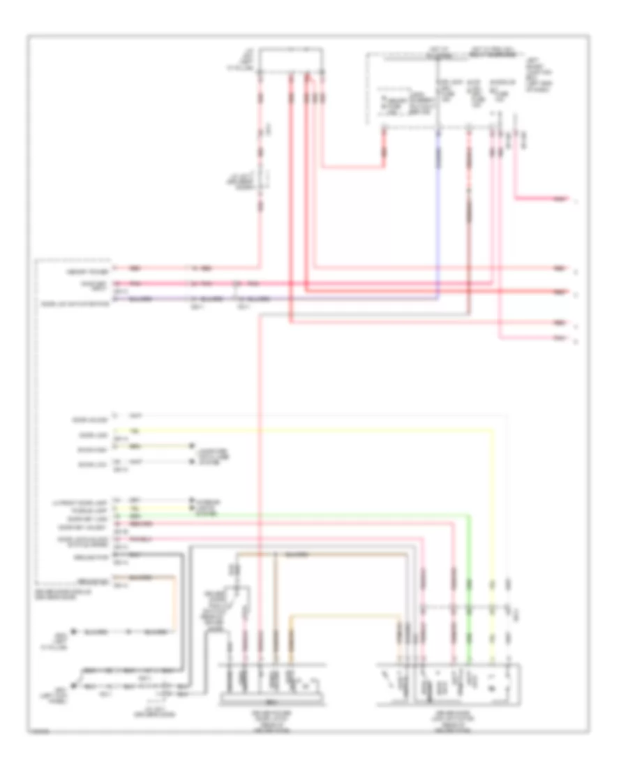 https://portal-diagnostov.com/license.html
Automotive Electricians Portal FZCO
Automotive Electricians Portal FZCO
https://portal-diagnostov.com/license.html
https://portal-diagnostov.com/license.html
Automotive Electricians Portal FZCO
Automotive Electricians Portal FZCOList of elements for Power Door Locks Wiring Diagram (1 of 4) for Hyundai Equus Ultimate 2014:
- Ajar switch
- B-can high
- B-can low
- Computer data lines system
- D51-a
- D51-b
- D51-c
- Dd11
- Door key lock
- Door key unlock
- Door lck actuator pwr
- Door lock
- Door lock/unlock
- Door unlock
- Dr lock drv fuse 15a
- Driver door lock actuator (rear of driver door)
- Driver door module (driver's door)
- Driver door pawl switch (rear of driver door)
- Driver power door latch (rear of driver door)
- Ecu
- Fd11
- Gf01 (left kick panel)
- Gf03 (left "c" pillar)
- Ground
- Ground pwr
- Ground sig
- Ground signal
- Hot at all times
- Hot w/ pdm (ig1) relay energized
- I/p-lhc
- I/p-lhe
- Interior lights system
- J/c jd11 (driver's door)
- J/c jf01 (left "c" pillar)
- Key
- Leak current autocut device
- Left smart junction box (left end of dash)
- Lh front door lamp
- Lock
- Memory fuse 10a
- Memory power
- Module fuse 10a
- O/s hdl drv fuse 15a
- On/start input
- Pnk
- Puddle lamp
- Red
- Status inform
- Switch ajar
- Switch pawl
- Unlock
Power Door Locks Wiring Diagram (2 of 4) for Hyundai Equus Ultimate 2014
 https://portal-diagnostov.com/license.html
Automotive Electricians Portal FZCO
Automotive Electricians Portal FZCO
https://portal-diagnostov.com/license.html
https://portal-diagnostov.com/license.html
Automotive Electricians Portal FZCO
Automotive Electricians Portal FZCOList of elements for Power Door Locks Wiring Diagram (2 of 4) for Hyundai Equus Ultimate 2014:
- (right rear door) j/c jd41
- (right rear door) right rear door module
- B-can
- B/a horn
- Burglar alarm horn (lower left rear of engine compt)
- Communication lin
- Communication local
- Computer data lines system
- Dd41
- Dr lk
- Dr unlk
- E/r-e1a
- E/r-e1b
- Ecu
- Engine room junction box (right rear of engine compt)
- Ext buzzer
- Exterior lights system
- External buzzer (left front wheel housing)
- Fam
- Fam-a
- Fam-b
- Fam-c
- Fd41
- Ge03 (left front of engine compt)
- Ge04 (lower right rear of engine compt)
- Gf09 (behind right rear seat)
- Ground
- Ground signal
- Headlights system
- High
- Ill (+)
- Interior lights system
- J/c jd41 (right rear door)
- J/c je02 (under left end of dash)
- Lh head lamp hi
- Lh tail lp
- Low
- Nca
- On/start input
- P-gnd
- Pnk
- Power memory
- Power windows system
- Rear door mood lamp
- Red
- Rh head lamp hi
- Rh tail lp
- Right rear door lock actuator (rear of right door)
- Right rear door pawl switch (rear of right door)
- Right rear power door latch (rear of right door)
- Switch ajar
- Switch pawl
- Unlock status door lock/
Power Door Locks Wiring Diagram (3 of 4) for Hyundai Equus Ultimate 2014
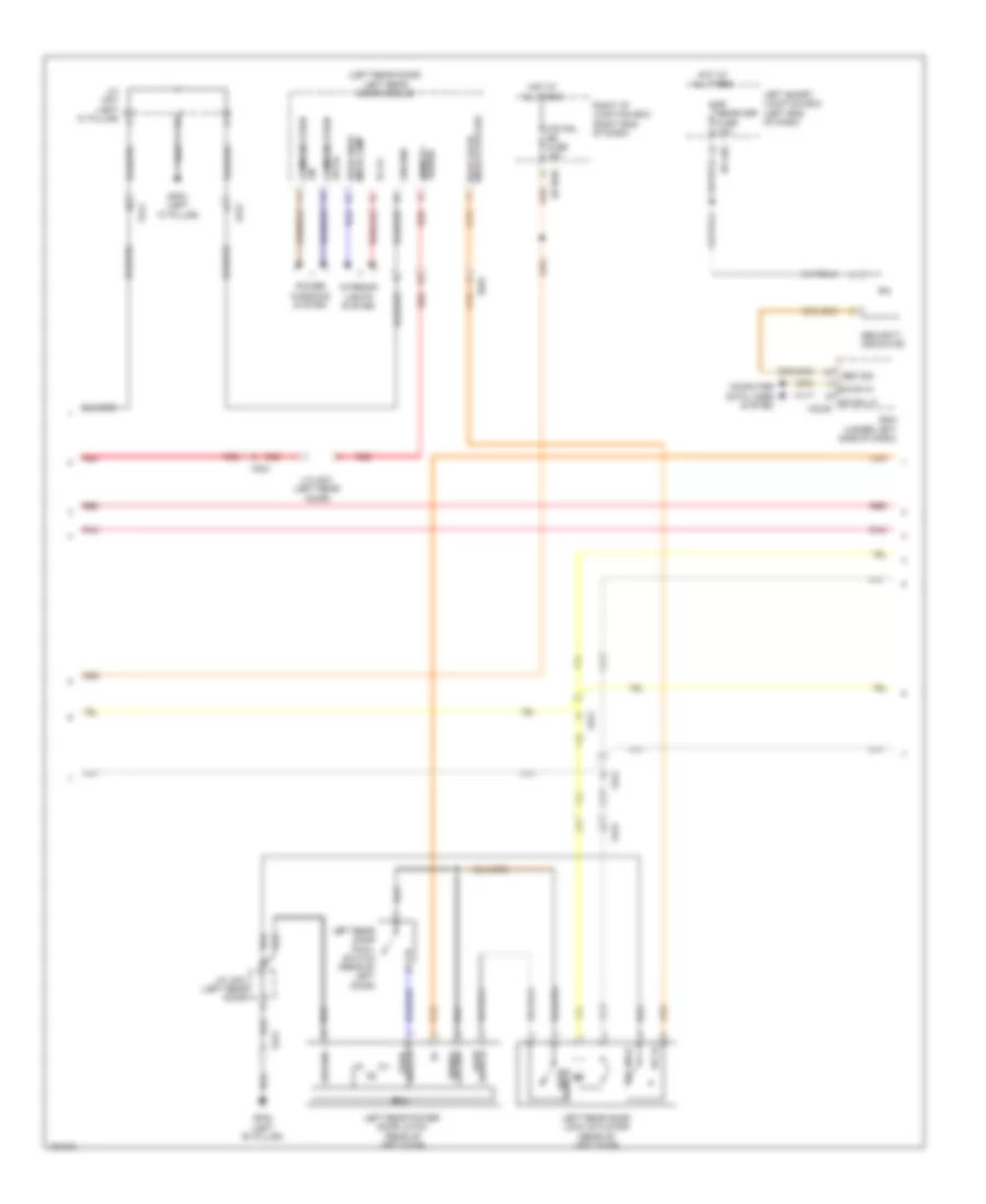 https://portal-diagnostov.com/license.html
Automotive Electricians Portal FZCO
Automotive Electricians Portal FZCO
https://portal-diagnostov.com/license.html
https://portal-diagnostov.com/license.html
Automotive Electricians Portal FZCO
Automotive Electricians Portal FZCOList of elements for Power Door Locks Wiring Diagram (3 of 4) for Hyundai Equus Ultimate 2014:
- (left rear door) left rear door module
- B-can hi
- B-can lo
- Bcm (under left side of dash)
- Communication lin
- Communication local
- Computer data lines system
- Dd31
- Dr lk
- Dr unlk
- Ecu
- Fd21
- Fd31
- Fd41
- Gf02 (left "b" pillar)
- Gf03 (left "c" pillar)
- Ground
- Ground signal
- Hot at all times
- I/p-lhg
- I/p-rhe
- Ill (+)
- Interior lights system
- J/c jd31 (left rear door)
- J/c jf01 (left "c" pillar)
- Left rear door lock actuator (rear of left door)
- Left rear door pawl switch (rear of left door)
- Left rear power door latch (rear of left door)
- Left smart junction box (left end of dash)
- M32-b
- O/s hdl rr fuse 15a
- Pnk
- Power memory
- Power windows system
- Rear door mood lamp
- Red
- Rf receiver fuse 10a
- Right i/p junction box (right end of dash)
- Sec sig
- Security indicator
- Switch ajar
- Switch pawl
- Unlock status door lock/
Power Door Locks Wiring Diagram (4 of 4) for Hyundai Equus Ultimate 2014
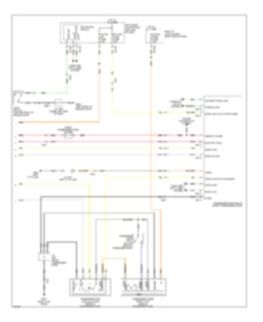 https://portal-diagnostov.com/license.html
Automotive Electricians Portal FZCO
Automotive Electricians Portal FZCO
https://portal-diagnostov.com/license.html
https://portal-diagnostov.com/license.html
Automotive Electricians Portal FZCO
Automotive Electricians Portal FZCOList of elements for Power Door Locks Wiring Diagram (4 of 4) for Hyundai Equus Ultimate 2014:
- (front passenger's door) j/c jd21
- B-can
- B-can high
- B-can low
- Computer data lines system
- D61-a
- D61-b
- D61-c
- Dd21
- Door lock
- Door lock actuator power
- Door lock status inform
- Door unlock
- Dr lk
- Dr lock pass fuse 15a
- Dr unlk
- Ecu
- Ee21
- Ee31
- Fd21
- Ge03 (left front of engine compt)
- Gf03 (left "c" pillar)
- Gf05 (right kick panel)
- Ground
- Ground signal
- High
- Hood sw
- Hood switch (center front of engine compt)
- Hot at all times
- I/p-lhc
- I/p-lhe
- I/p-lhf
- I/p-rhe
- Interior lights system
- Ips control module
- J/c jd21 (front passenger's door)
- J/c je02 (under left end of dash)
- J/c jf01 (left "c" pillar)
- Left smart junction box (left end of dash)
- Low
- Memory power
- Nca
- O/s hdl pass fuse 15a
- O/s hdl rr fuse 15a
- On/start input
- P-gnd
- Passenger door lock actuator (rear of passenger door)
- Passenger door module (front passenger's door)
- Passenger door pawl switch (rear of passenger door)
- Passenger power door latch (rear of passenger door)
- Pnk
- Power distribution system
- Puddle lamp
- Red
- Rh front door lamp
- Right i/p junction box (right end of dash)
- S-gnd
- Switch ajar
- Switch pawl
POWER MIRRORS
Power Mirrors Wiring Diagram for Hyundai Equus Ultimate 2014
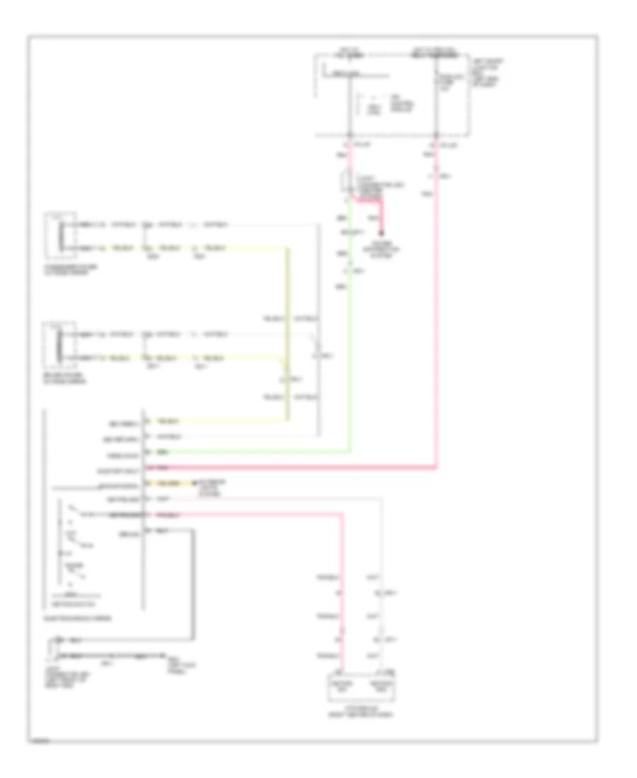 https://portal-diagnostov.com/license.html
Automotive Electricians Portal FZCO
Automotive Electricians Portal FZCO
https://portal-diagnostov.com/license.html
https://portal-diagnostov.com/license.html
Automotive Electricians Portal FZCO
Automotive Electricians Portal FZCOList of elements for Power Mirrors Wiring Diagram for Hyundai Equus Ultimate 2014:
- Backup signal
- Dd11
- Dd21
- Driver power outside mirror
- Ecm mirror
- Electrochromic mirror
- Exterior lights system
- Fd11
- Fd21
- Fr11
- Gf01 (left kick panel)
- Ground
- Homelink b+
- Hot at all times
- Hot w/ pdm (ig1) relay energized
- I/p-lhc
- I/p-lhf
- Ips 3 (1ch)
- Ips 3 ctrl
- Ips control module
- Joint connector jm01 (center of dash)
- Joint connector jr01 (left front of roof trim)
- Keypad gnd
- Keypad sig
- Keypad switch
- Left smart junction box (left end of dash)
- M06
- Mf11
- Module 2 fuse 10a
- Mts module (right center of dash)
- Nca
- Oec feed(+)
- Oec return(-)
- On/start input
- Passenger power outside mirror
- Phone
- Pnk
- Power distribution system
- Sos
- Uvo
POWER SEATS
Climate Control Seats Wiring Diagram (1 of 4) for Hyundai Equus Ultimate 2014
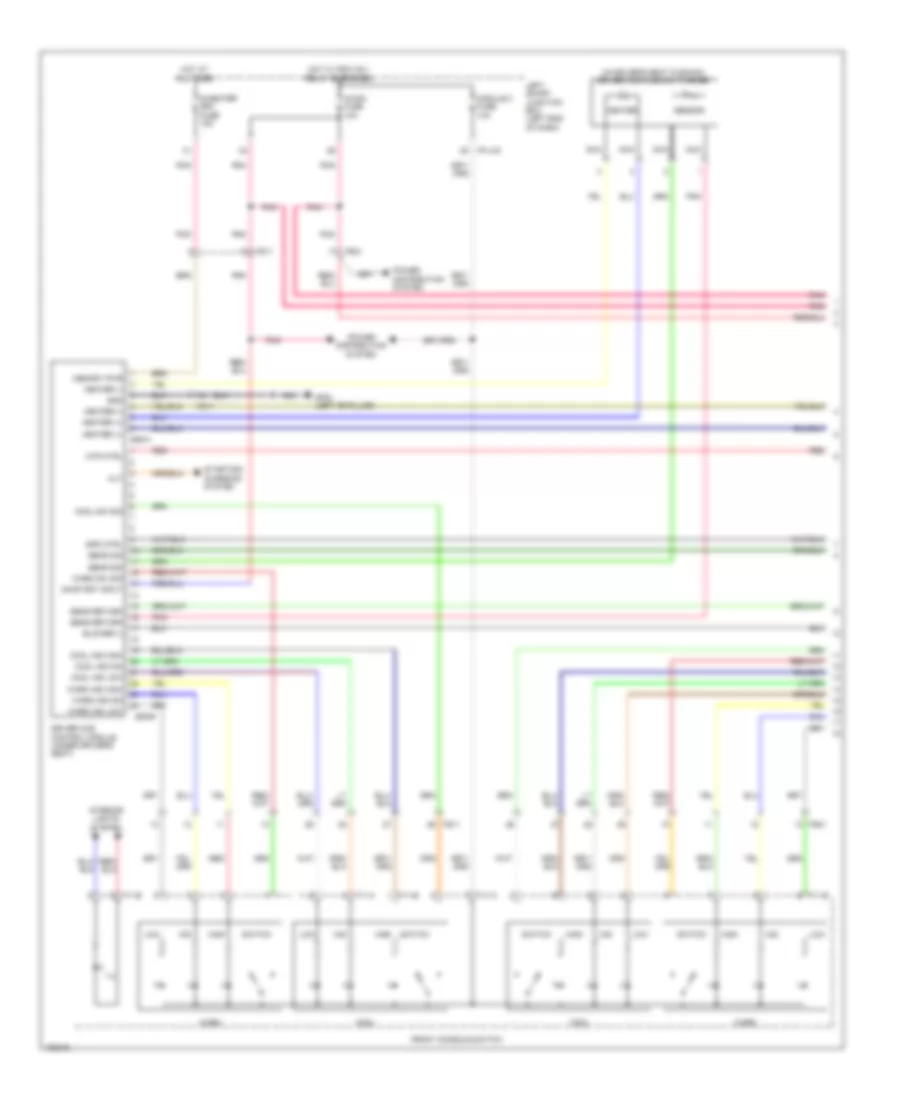 https://portal-diagnostov.com/license.html
Automotive Electricians Portal FZCO
Automotive Electricians Portal FZCO
https://portal-diagnostov.com/license.html
https://portal-diagnostov.com/license.html
Automotive Electricians Portal FZCO
Automotive Electricians Portal FZCOList of elements for Climate Control Seats Wiring Diagram (1 of 4) for Hyundai Equus Ultimate 2014:
- (in driver's seat cushion) driver ccs cushion warmer
- A/con fuse 10a
- Alt
- Blower (-)
- Cool
- Cool ind high
- Cool ind low
- Cool ind mid
- Cool sw sig
- Driver ccs control module (under driver's seat)
- F11-a
- F11-b
- Front console switch
- Fs11
- Fs21
- Gf02 (left "b" pillar)
- Gnd
- Heater
- Heater (+)
- Heater (-)
- High
- Hot at all times
- Hot w/ pdm (ig1) relay energized
- I/p-lhc
- Ill
- Interior lights system
- Left smart junction box (left end of dash)
- Low
- Memory pwr
- Mid
- Module 3 fuse 10a
- Mtr ctrl
- Nca
- On/start input
- Pnk
- Power distribution system
- Red
- S/heater drv fuse 15a
- S06-a
- S06-b
- Sens return
- Sens sig
- Sensor
- Spd ctrl
- Starting/ charging system
- Switch
- Warm
- Warm ind high
- Warm ind low
- Warm ind mid
- Warm sw sig
Climate Control Seats Wiring Diagram (2 of 4) for Hyundai Equus Ultimate 2014
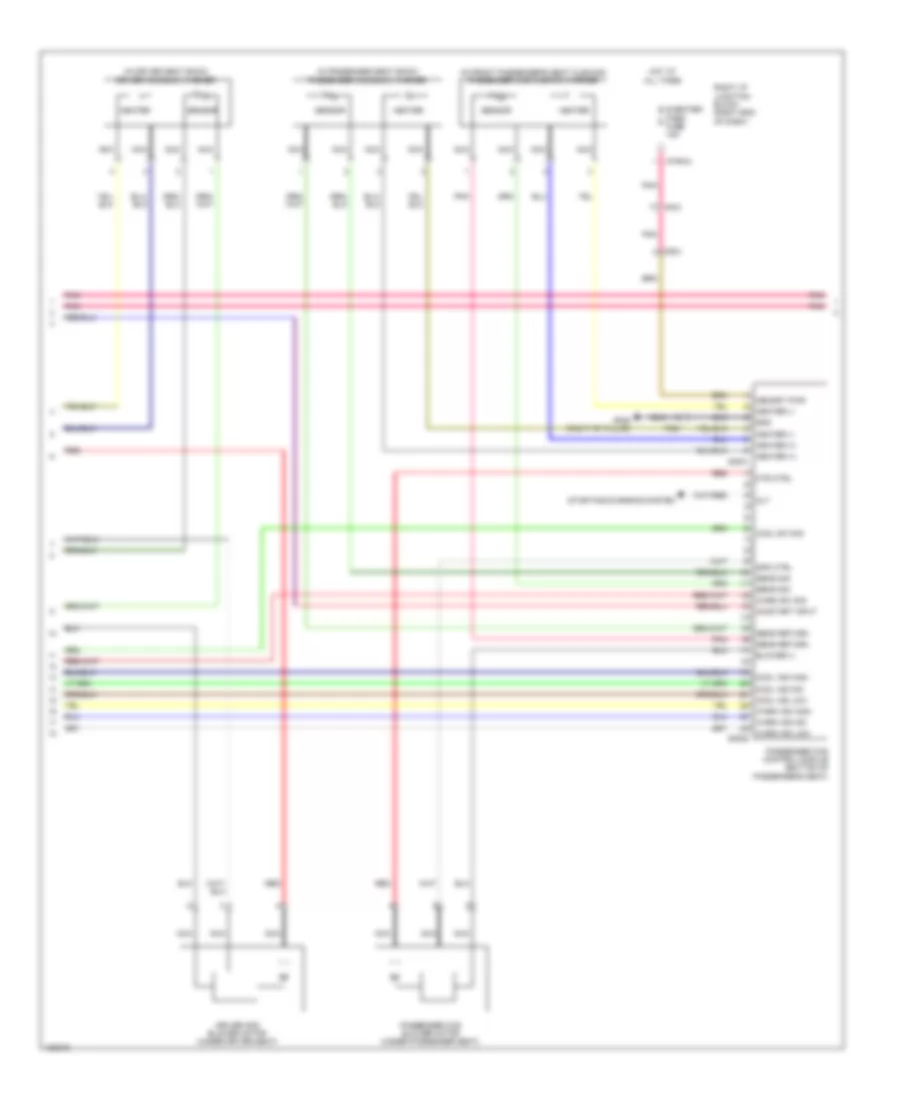 https://portal-diagnostov.com/license.html
Automotive Electricians Portal FZCO
Automotive Electricians Portal FZCO
https://portal-diagnostov.com/license.html
https://portal-diagnostov.com/license.html
Automotive Electricians Portal FZCO
Automotive Electricians Portal FZCOList of elements for Climate Control Seats Wiring Diagram (2 of 4) for Hyundai Equus Ultimate 2014:
- (in driver seat back) driver ccs back warmer
- (in front passenger's seat cushion) passenger ccs cushion warmer
- (in passenger seat back) passenger ccs back warmer
- Alt
- Blower (-)
- Cool ind high
- Cool ind low
- Cool ind mid
- Cool sw sig
- Driver ccs blower motor (under driver seat)
- Fs21
- Gf06 (right "b" pillar)
- Gnd
- Heater
- Heater (+)
- Heater (-)
- Hot at all times
- I/p-rha
- Memory pwr
- Mf21
- Mtr ctrl
- Nca
- On/start input
- Passenger ccs blower motor (under passenger seat)
- Passenger ccs control module (bottom of passenger's seat)
- Pnk
- Red
- Right i/p junction block (right end of dash)
- S/heater pass fuse 15a
- S46-a
- S46-b
- Sens return
- Sens sig
- Sensor
- Spd ctrl
- Starting/charging system
- Warm ind high
- Warm ind low
- Warm ind mid
- Warm sw sig
Climate Control Seats Wiring Diagram (3 of 4) for Hyundai Equus Ultimate 2014
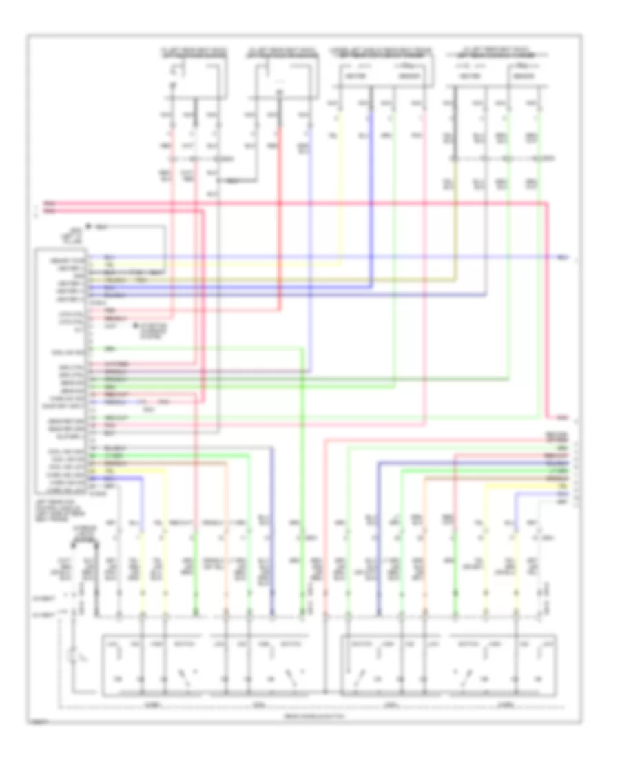 https://portal-diagnostov.com/license.html
Automotive Electricians Portal FZCO
Automotive Electricians Portal FZCO
https://portal-diagnostov.com/license.html
https://portal-diagnostov.com/license.html
Automotive Electricians Portal FZCO
Automotive Electricians Portal FZCOList of elements for Climate Control Seats Wiring Diagram (3 of 4) for Hyundai Equus Ultimate 2014:
- (in left rear seat back) left rear back blower
- (in left rear seat back) left rear ccs back warmer
- (in left rear seat back) left rear cushion blower
- (under left side of rear seat frame) left rear ccs cushion warmer
- 5:5 seat
- 6:4 seat
- Alt
- Blower (-)
- Cool
- Cool ind high
- Cool ind low
- Cool ind mid
- Cool sw sig
- Fs31
- Gf03 (left "c" pillar)
- Gnd
- Heater
- Heater (+)
- Heater (-)
- High
- Ill
- Interior lights system
- Left rear ccs control module (left side of rear seat frame)
- Low
- Memory pwr
- Mid
- Mtr ctrl
- Nca
- On/start input
- Pnk
- Rear console switch
- Red
- S106-a
- S106-b
- S27-a
- S27-b
- S37-a
- S37-b
- Sens return
- Sens sig
- Sensor
- Spd ctrl
- Ss31
- Ss32
- Ss41
- Starting/ charging system
- Switch
- Warm
- Warm ind high
- Warm ind low
- Warm ind mid
- Warm sw sig
Climate Control Seats Wiring Diagram (4 of 4) for Hyundai Equus Ultimate 2014
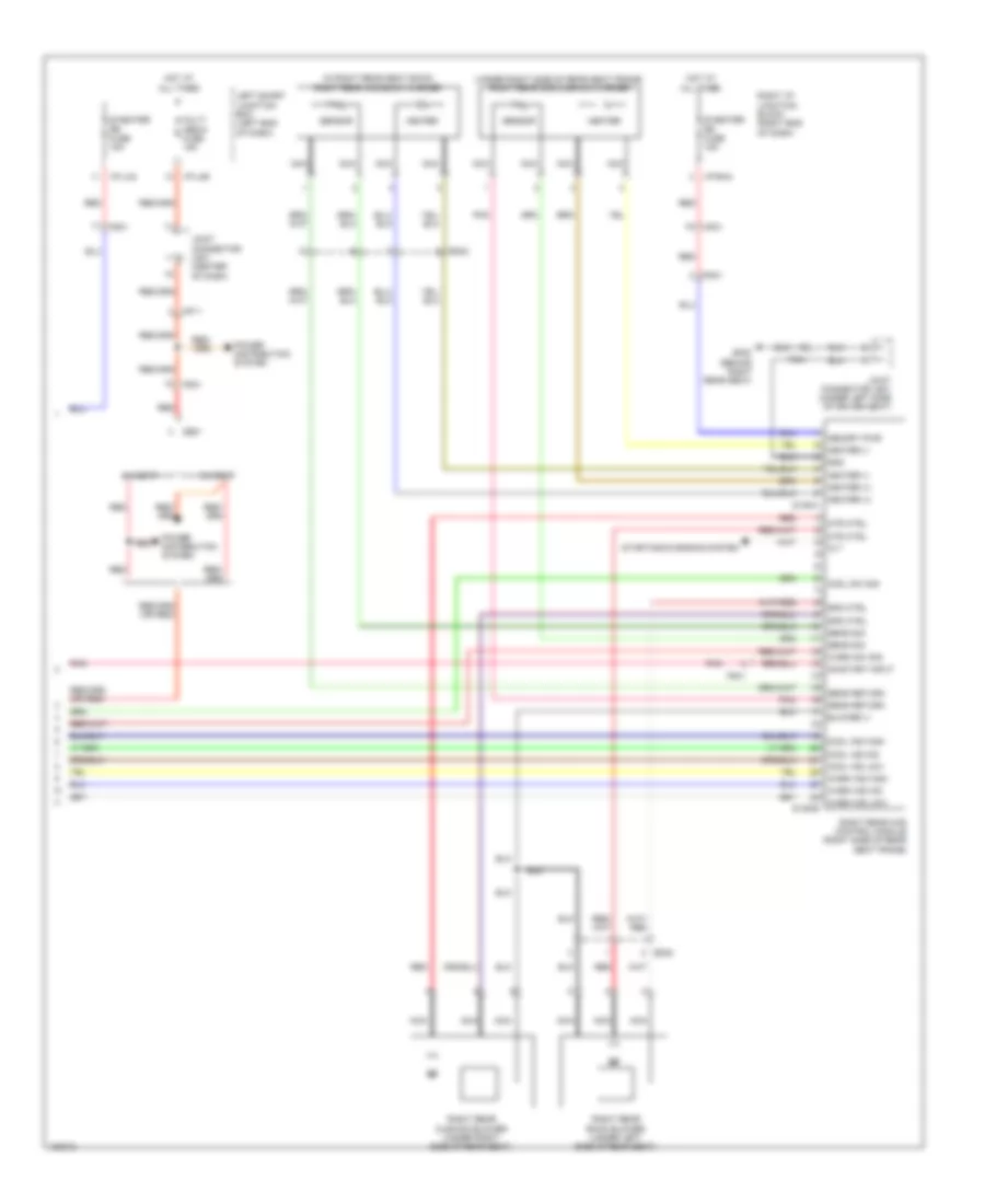 https://portal-diagnostov.com/license.html
Automotive Electricians Portal FZCO
Automotive Electricians Portal FZCO
https://portal-diagnostov.com/license.html
https://portal-diagnostov.com/license.html
Automotive Electricians Portal FZCO
Automotive Electricians Portal FZCOList of elements for Climate Control Seats Wiring Diagram (4 of 4) for Hyundai Equus Ultimate 2014:
- (in right rear seat back) right rear ccs back warmer
- (under right side of rear seat frame) right rear ccs cushion warmer
- 5:5 seat
- 6:4 seat
- Alt
- Blower (-)
- Cool ind high
- Cool ind low
- Cool ind mid
- Cool sw sig
- Fs31
- Fs41
- Gf08 (behind right rear seat)
- Gnd
- Heater
- Heater (+)
- Heater (-)
- Hot at all times
- I/p-lhc
- I/p-lhg
- I/p-rha
- Joint connector jm01 (center of dash)
- Joint connector js31 (under left side of driver seat)
- Left smart junction box (left end of dash)
- Memory pwr
- Mf11
- Mf21
- Mtr ctrl
- Multi media fuse 15a
- Nca
- On/start input
- Pnk
- Power distribution system
- Red
- Right i/p junction block (right end of dash)
- Right rear back blower (under left side of rear seat)
- Right rear ccs control module (right side of rear seat frame)
- Right rear cushion blower (under right side of rear seat)
- S/heater rr fuse 15a
- S146-a
- S146-b
- Sens return
- Sens sig
- Sensor
- Spd ctrl
- Ss31
- Ss42
- Starting/charging system
- Warm ind high
- Warm ind low
- Warm ind mid
- Warm sw sig
Heated Seats Wiring Diagram for Hyundai Equus Ultimate 2014
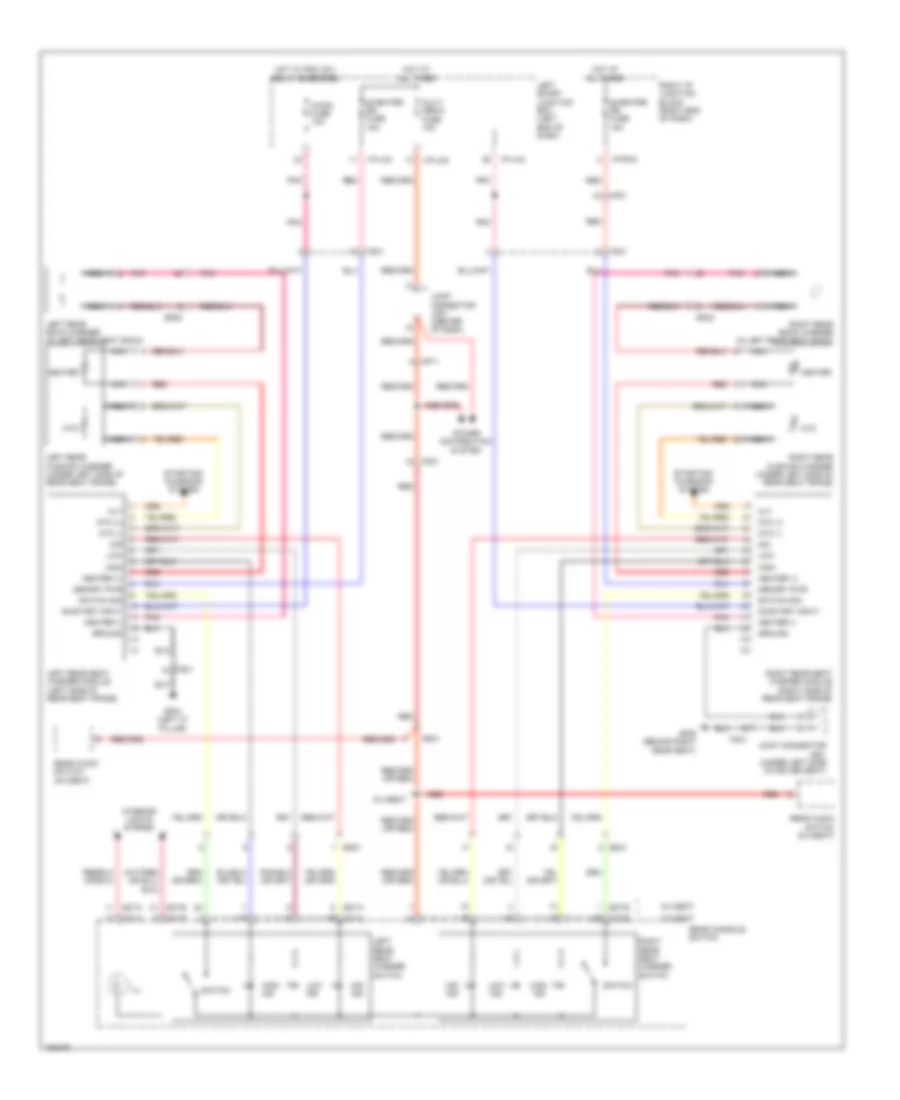 https://portal-diagnostov.com/license.html
Automotive Electricians Portal FZCO
Automotive Electricians Portal FZCO
https://portal-diagnostov.com/license.html
https://portal-diagnostov.com/license.html
Automotive Electricians Portal FZCO
Automotive Electricians Portal FZCOList of elements for Heated Seats Wiring Diagram for Hyundai Equus Ultimate 2014:
- 5:5 seat
- 6:4 seat
- A/con fuse 10a
- Alt
- Fs31
- Fs41
- Gf03 (left "c" pillar)
- Gf08 (behind right rear seat)
- Ground
- Heater
- Heater (+)
- Heater (-)
- High
- High ind
- Hot at all times
- Hot w/ pdm (ig1) relay energized
- I/p-lhc
- I/p-lhg
- I/p-rha
- Ill
- Interior lights system
- Joint connector jm01 (center of dash)
- Joint connector js31 (under left side of driver seat)
- Left rear back warmer (in left rear seat back)
- Left rear cushion warmer (under left side of rear seat frame)
- Left rear seat warmer module (left side of rear seat frame)
- Left rear seat warmer switch
- Left smart junction box (left end of dash)
- Low
- Low ind
- Memory pwr
- Mf11
- Mf21
- Mid
- Mid ind
- Multi media fuse 15a
- Nca
- Ntc
- Ntc (+)
- Ntc (-)
- On/start input
- Pnk
- Power distribution system
- Rear audio switch (5:5 seat)
- Rear audio switch (6:4 seat)
- Rear console switch
- Red
- Right i/p junction block (right end of dash)
- Right rear back warmer (in left rear seat back)
- Right rear cushion warmer (under left side of rear seat frame)
- Right rear seat warmer module (right side of rear seat frame)
- Right rear seat warmer switch
- S/heater rr fuse 15a
- S27-a
- S27-b
- S37-a
- S37-b
- Ss31
- Ss32
- Ss41
- Ss42
- Starting/ charging system
- Switch
- Switch sig
Heated Steering Wheel Wiring Diagram for Hyundai Equus Ultimate 2014
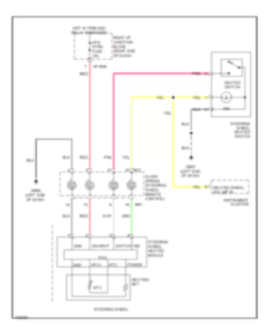 https://portal-diagnostov.com/license.html
Automotive Electricians Portal FZCO
Automotive Electricians Portal FZCO
https://portal-diagnostov.com/license.html
https://portal-diagnostov.com/license.html
Automotive Electricians Portal FZCO
Automotive Electricians Portal FZCOList of elements for Heated Steering Wheel Wiring Diagram for Hyundai Equus Ultimate 2014:
- Clock spring (steering wheel remote control)
- Ecu
- Gm01 (left end of dash)
- Gm06 (left end of dash)
- Gnd
- Heated switch
- Heated wheel sw lmp in
- Heating mat
- Hot w/ pdm (ig2) relay energized
- Htd strg fuse 15a
- I/p-rha
- Ind
- Instrument cluster
- M13
- M91
- Ntc
- Ntc+
- Ntc-
- On input
- Pnk
- Power
- Red
- Right i/p junction block (right end of dash)
- Steering wheel
- Steering wheel heated module
- Steering wheel heated switch
- Switch
Lumbar Wiring Diagram for Hyundai Equus Ultimate 2014
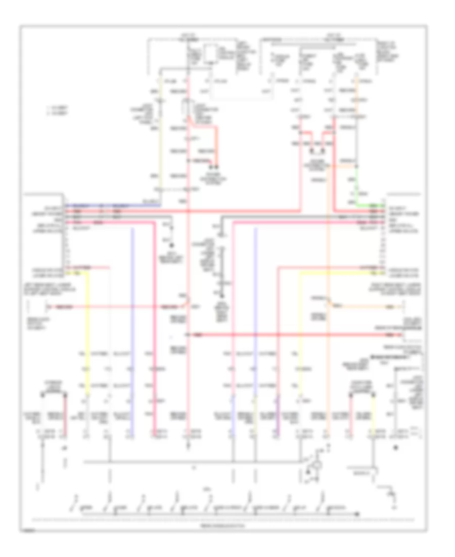 https://portal-diagnostov.com/license.html
Automotive Electricians Portal FZCO
Automotive Electricians Portal FZCO
https://portal-diagnostov.com/license.html
https://portal-diagnostov.com/license.html
Automotive Electricians Portal FZCO
Automotive Electricians Portal FZCOList of elements for Lumbar Wiring Diagram for Hyundai Equus Ultimate 2014:
- 12v
- 5:5 seat
- 6:4 seat
- B-can ic
- Computer data lines system
- Cool box (5:5 seat) (rear of rear console)
- Cpu
- Deflate
- Deflate all
- Fs31
- Fs41
- Gf08 (behind right rear seat)
- Gf10 (behind left rear seat)
- Gnd
- Hot at all times
- Hot in on
- I/p-lhb
- I/p-lhg
- I/p-rha
- I/p-rhd
- Ice box fuse 15a
- Ig2
- Inflate
- Interior lights system
- Ips control module
- Joint connector jf03 (left kick panel)
- Joint connector jm01 (center of dash)
- Joint connector js31 (under left side of driver seat)
- Left rear seat lumbar support control module (in left seat back)
- Left smart junction box (left end of dash)
- Leg down
- Leg support rr fuse 10a
- Leg up
- Lower
- Lower inflate
- Memory power
- Mf11
- Mf21
- Middle inflate
- Module fuse 10a
- Multi media fuse 15a
- On input
- P/seat rr fuse 20a
- Pnk
- Power distribution system
- Rear audio switch (5:5 seat)
- Rear audio switch (6:4 seat)
- Rear console switch
- Red
- Right i/p junction block (right end of dash)
- Right rear seat lumbar support control module (in right seat back)
- S27-a
- S27-b
- S37-a
- S37-b
- Ss31
- Ss32
- Ss41
- Ss42
- Upper
- Upper inflate
- Work in front
- Work in rear
Rear Power Seat Wiring Diagram, 5:5 Seat (1 of 2) for Hyundai Equus Ultimate 2014
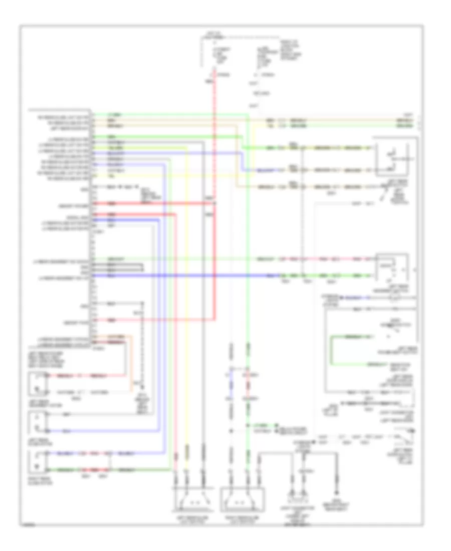 https://portal-diagnostov.com/license.html
Automotive Electricians Portal FZCO
Automotive Electricians Portal FZCO
https://portal-diagnostov.com/license.html
https://portal-diagnostov.com/license.html
Automotive Electricians Portal FZCO
Automotive Electricians Portal FZCOList of elements for Rear Power Seat Wiring Diagram, 5:5 Seat (1 of 2) for Hyundai Equus Ultimate 2014:
- Dd31
- Down
- Easy access switch
- Fd31
- Fs31
- Fs41
- Gf02 (left "b" pillar)
- Gf08 (behind right rear seat)
- Gf10 (behind left rear seat)
- Gnd
- Hot at all times
- I/p-rha
- I/p-rhd
- Ill
- Interior lights system
- Joint connector jd31 (left rear door)
- Joint connector js31 (under left side of driver seat)
- Left rear door module (left rear door)
- Left rear door sw
- Left rear door switch
- Left rear door switch (left "c" pillar)
- Left rear headrest motor
- Left rear headrest switch
- Left rear power seat relay box (left side of rear seat back frame)
- Left rear power seat switch
- Left rear slide limit switch
- Left rear slide motor
- Left rear slide switch
- Leg support rr fuse 10a
- Lh rear headrest mtr dn
- Lh rear headrest mtr up
- Lh rear headrest sw down
- Lh rear headrest sw up
- Lh rear slide limit sw fr
- Lh rear slide limit sw rr
- Lh rear slide motor fr
- Lh rear slide motor rr
- Lh rear slide sw fr
- Lh rear slide sw rr
- Memory power
- Memory pwr
- Mf21
- Nca
- P/seat rr fuse 20a
- Pnk
- Rear pwr seat sw
- Red
- Relax power seats circuit
- Rh rear slide limit sw fr
- Rh rear slide limit sw rr
- Rh rear slide motor fr
- Rh rear slide motor rr
- Rh rear slide sw fr
- Rh rear slide sw rr
- Right i/p junction block (right end of dash)
- Right rear slide limit switch
- Right rear slide motor
- S126-1
- S126-2
- Signal gnd
- Ss31
- Ss32
- Ss41
Rear Power Seat Wiring Diagram, 5:5 Seat (2 of 2) for Hyundai Equus Ultimate 2014
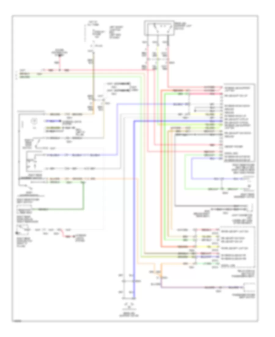 https://portal-diagnostov.com/license.html
Automotive Electricians Portal FZCO
Automotive Electricians Portal FZCO
https://portal-diagnostov.com/license.html
https://portal-diagnostov.com/license.html
Automotive Electricians Portal FZCO
Automotive Electricians Portal FZCOList of elements for Rear Power Seat Wiring Diagram, 5:5 Seat (2 of 2) for Hyundai Equus Ultimate 2014:
- (not used)
- Dd21
- Dd41
- Down
- Easy access switch
- Fd21
- Fd41
- Fr rear leg support limit sw
- Fr rr leg spt limit sw
- Fs21
- Fs22
- Fs31
- Fs41
- Gf03 (left "c" pillar)
- Gf08 (behind right rear seat)
- Ground
- Hot at all times
- I/p-lhc
- Ill
- Interior lights system
- Joint connector js31 (under left side of driver seat)
- Left smart junction box (left end of dash)
- Memory power
- Module 1 fuse 10a
- Nca
- Passenger power seat switch
- Pnk
- Power distribution system
- Rear leg support limit switch
- Rear leg support motor
- Rear pwr seat sw
- Red
- Relax module (bottom of passenger's seat)
- Rh rear hr motor dn
- Rh rear hr motor up
- Rh rear hr sw down
- Rh rear hr sw up
- Rh rear slide sw fr
- Rh rear slide sw rr
- Right rear door module (right rear door)
- Right rear door switch
- Right rear door switch (right "c" pillar)
- Right rear headrest motor
- Right rear headrest switch
- Right rear power seat relay box (right side of rear seat back frame)
- Right rear power seat switch
- Rr leg spt sw dwn
- Rr leg spt sw up
- Rr leg supt mtr dn rr rear leg support limit sw
- Rr leg supt mtr up
- Rr leg supt sw down
- Rr leg supt sw up
- Rr rr leg spt limit sw
- S70-a
- S70-c
- S70-d
- Signal gnd
- Signal line
- Ss42
- Ss43
Rear Power Seat Wiring Diagram, 6:4 Seat (1 of 2) for Hyundai Equus Ultimate 2014
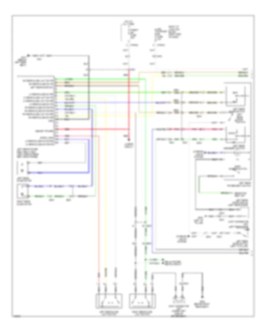 https://portal-diagnostov.com/license.html
Automotive Electricians Portal FZCO
Automotive Electricians Portal FZCO
https://portal-diagnostov.com/license.html
https://portal-diagnostov.com/license.html
Automotive Electricians Portal FZCO
Automotive Electricians Portal FZCOList of elements for Rear Power Seat Wiring Diagram, 6:4 Seat (1 of 2) for Hyundai Equus Ultimate 2014:
- Dd31
- Down
- Easy access switch
- Fd31
- Ff01
- Fs31
- Fs41
- Gf02 (left "b" pillar)
- Gf08 (behind right rear seat)
- Gf10 (behind left rear seat)
- Gnd
- Hot at all times
- I/p-rha
- I/p-rhd
- Ill
- Interior lights system
- Joint connector jd31 (left rear door)
- Joint connector js31 (under left side of driver seat)
- Left rear door module (left rear door)
- Left rear door sw
- Left rear door switch
- Left rear door switch (left "c" pillar)
- Left rear headrest switch
- Left rear power seat relay box (left side of rear seat back frame)
- Left rear power seat switch
- Left rear slide limit switch
- Left rear slide motor
- Left rear slide switch
- Leg support rr fuse 10a
- Lh rear slide limit sw fr
- Lh rear slide limit sw rr
- Lh rear slide motor fr
- Lh rear slide motor rr
- Lh rear slide sw fr
- Lh rear slide sw rr
- Lumbar circuit
- Memory power
- Mf21
- Nca
- P/seat rr fuse 20a
- Pnk
- Rear pwr seat sw
- Red
- Relax power seats circuit
- Rh rear slide limit sw fr
- Rh rear slide limit sw rr
- Rh rear slide motor fr
- Rh rear slide motor rr
- Rh rear slide sw fr
- Rh rear slide sw rr
- Right i/p junction block (right end of dash)
- Right rear slide limit switch
- Right rear slide motor
- Signal gnd
- Ss31
- Ss41
Rear Power Seat Wiring Diagram, 6:4 Seat (2 of 2) for Hyundai Equus Ultimate 2014
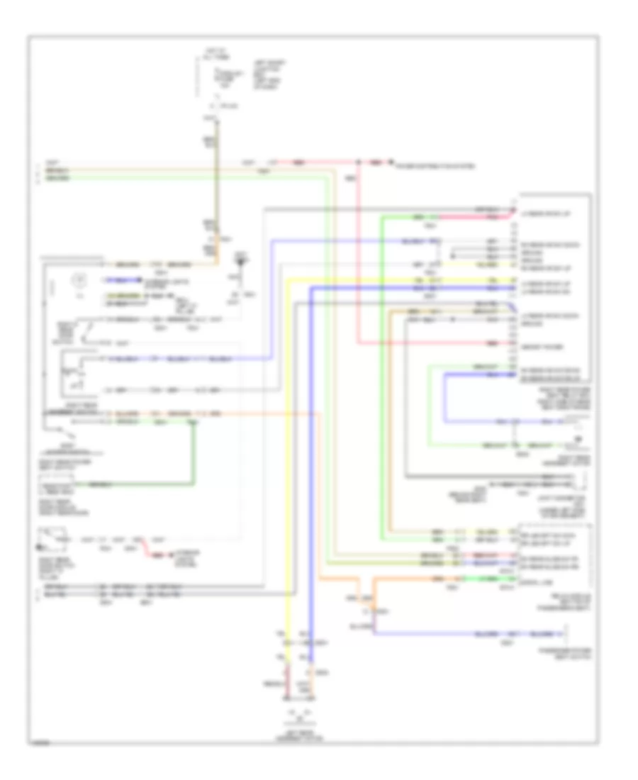 https://portal-diagnostov.com/license.html
Automotive Electricians Portal FZCO
Automotive Electricians Portal FZCO
https://portal-diagnostov.com/license.html
https://portal-diagnostov.com/license.html
Automotive Electricians Portal FZCO
Automotive Electricians Portal FZCOList of elements for Rear Power Seat Wiring Diagram, 6:4 Seat (2 of 2) for Hyundai Equus Ultimate 2014:
- (not used)
- Dd21
- Dd41
- Down
- Easy access switch
- Fd21
- Fd41
- Fs21
- Fs22
- Fs41
- Gf03 (left "c" pillar)
- Gf08 (behind right rear seat)
- Ground
- Hot at all times
- I/p-lhc
- Ill
- Interior lights system
- Joint connector js31 (under left side of driver seat)
- Left rear headrest motor
- Left smart junction box (left end of dash)
- Lh rear hr sw dn
- Lh rear hr sw down
- Lh rear hr sw up
- Memory power
- Module 1 fuse 10a
- Nca
- Passenger power seat switch
- Pnk
- Power distribution system
- Rear pwr seat sw
- Red
- Relax module (bottom of passenger's seat)
- Rh rear hr motor dn
- Rh rear hr motor up
- Rh rear hr sw down
- Rh rear hr sw up
- Rh rear slide sw fr
- Rh rear slide sw rr
- Right rear door module (right rear door)
- Right rear door switch
- Right rear door switch (right "c" pillar)
- Right rear headrest motor
- Right rear headrest switch
- Right rear power seat relay box (right side of rear seat back frame)
- Right rear power seat switch
- Rr leg spt sw dwn
- Rr leg spt sw up
- S70-a
- S70-c
- Signal line
- Ss31
- Ss32
- Ss41
- Ss42
Relax Power Seat Wiring Diagram (1 of 3) for Hyundai Equus Ultimate 2014
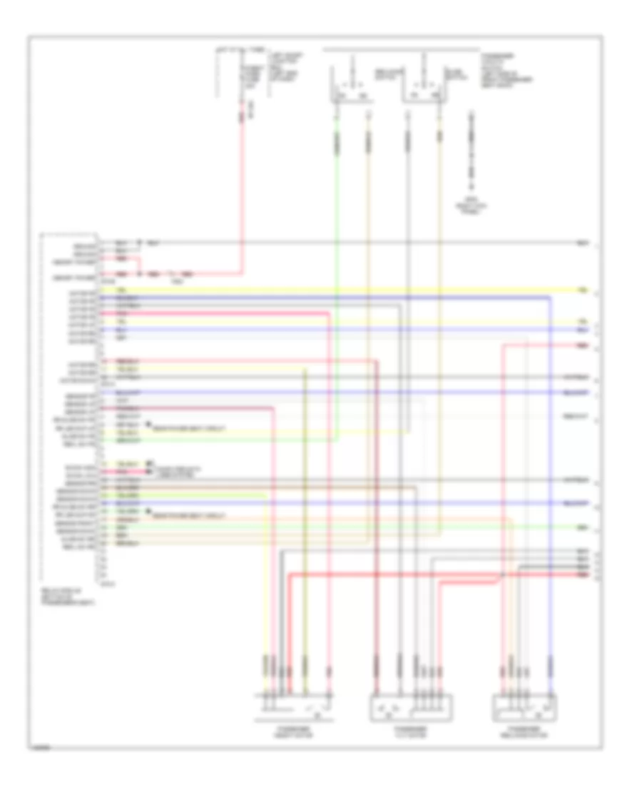 https://portal-diagnostov.com/license.html
Automotive Electricians Portal FZCO
Automotive Electricians Portal FZCO
https://portal-diagnostov.com/license.html
https://portal-diagnostov.com/license.html
Automotive Electricians Portal FZCO
Automotive Electricians Portal FZCOList of elements for Relax Power Seat Wiring Diagram (1 of 3) for Hyundai Equus Ultimate 2014:
- B-can high
- B-can low
- Computer data lines system
- Fs21
- Gf05 (right kick panel)
- Ground
- Hot at all times
- I/p-lha
- Left smart junction box (left end of dash)
- Memory power
- Motor down
- Motor fr
- Motor rr
- Motor up
- P/seat pass fuse 30a
- Passenger height motor
- Passenger reclining motor
- Passenger tilt motor
- Passenger walk in switch (left side of front passenger seat back)
- Pnk
- Rear power seat circuit
- Recl sw fr
- Recl sw rr
- Reclining switch
- Red
- Relax module (bottom of passenger's seat)
- Rr leg sup dn
- Rr leg sup up
- Rr slide sw fr
- Rr slide sw rr
- S70-a
- S70-b
- S70-c
- Sensor down
- Sensor fr
- Sensor front
- Sensor rr
- Sensor up
- Slide sw fr
- Slide sw rr
- Slide switch
Relax Power Seat Wiring Diagram (2 of 3) for Hyundai Equus Ultimate 2014
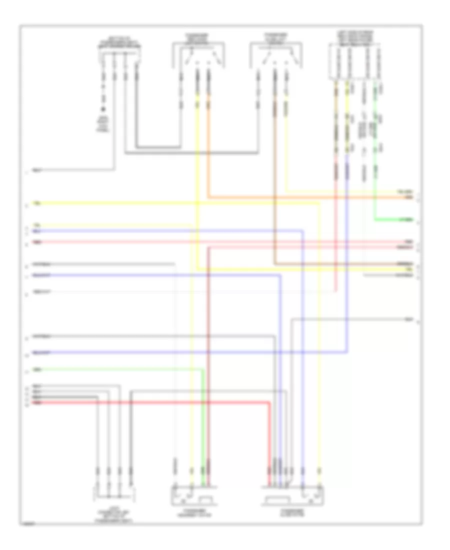 https://portal-diagnostov.com/license.html
Automotive Electricians Portal FZCO
Automotive Electricians Portal FZCO
https://portal-diagnostov.com/license.html
https://portal-diagnostov.com/license.html
Automotive Electricians Portal FZCO
Automotive Electricians Portal FZCOList of elements for Relax Power Seat Wiring Diagram (2 of 3) for Hyundai Equus Ultimate 2014:
- (bottom of passenger's seat) joint connector js21
- (left side of rear seat back frame) left rear power seat relay box
- Fs21
- Fs31
- Gf05 (right kick panel)
- Joint connector js21 (bottom of passenger's seat)
- Nca
- Passenger headrest motor
- Passenger reclining limit switch
- Passenger slide limit switch
- Passenger slide motor
- Red
- Rr slide sw fr
- Rr slide sw rr
- S126-1
- Ss31
- Ss41
Relax Power Seat Wiring Diagram (3 of 3) for Hyundai Equus Ultimate 2014
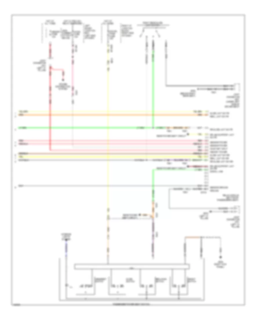 https://portal-diagnostov.com/license.html
Automotive Electricians Portal FZCO
Automotive Electricians Portal FZCO
https://portal-diagnostov.com/license.html
https://portal-diagnostov.com/license.html
Automotive Electricians Portal FZCO
Automotive Electricians Portal FZCOList of elements for Relax Power Seat Wiring Diagram (3 of 3) for Hyundai Equus Ultimate 2014:
- A/con fuse 10a
- Cpu
- Dd21
- Down
- Fd21
- Fs21
- Fs41
- Gf03 (left "c" pillar)
- Gf05 (right kick panel)
- Gf08 (behind right rear seat)
- Ground
- Headrest switch
- Height switch
- Hot at all times
- Hot w/ pdm (ig1) relay energized
- I/p-lhc
- I/p-rhe
- Ill
- Interior lights system
- Joint connector jf01 (left "c" pillar)
- Joint connector js31 (under left side of driver seat)
- Leak current autocut device
- Left smart junction box (left end of dash)
- Memory fuse 10a
- Memory power
- Mf21
- Nca
- O/s hdl pass fuse 15a
- On/start input
- Passenger power seat switch
- Pnk
- Power distribution system
- Rear power seat circuit
- Recl limit sw fr
- Recl limit sw rr
- Reclining switch
- Red
- Relax module (bottom of passenger's seat)
- Right i/p junction block (right end of dash)
- Right rear slide limit switch
- Rr leg support limit sw fr
- Rr leg support limit sw rr
- Rr slide limit sw fr
- Rr slide limit sw rr
- S70-d
- Sensor ground
- Sensor power
- Signal line
- Slide limit sw fr
- Slide limit sw rr
- Slide switch
POWER TOP/SUNROOF
Power Top/Sunroof Wiring Diagram for Hyundai Equus Ultimate 2014
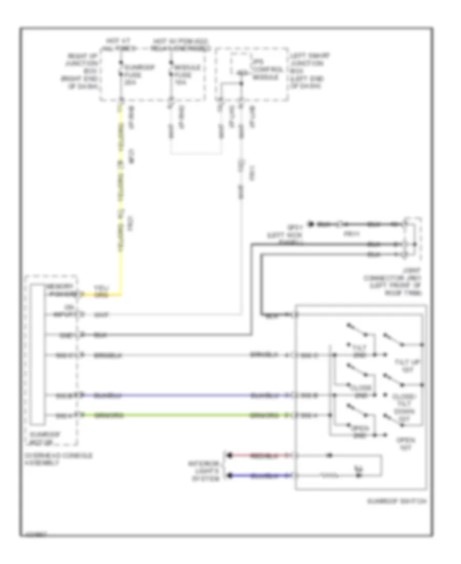 https://portal-diagnostov.com/license.html
Automotive Electricians Portal FZCO
Automotive Electricians Portal FZCO
https://portal-diagnostov.com/license.html
https://portal-diagnostov.com/license.html
Automotive Electricians Portal FZCO
Automotive Electricians Portal FZCOList of elements for Power Top/Sunroof Wiring Diagram for Hyundai Equus Ultimate 2014:
- Close 2nd
- Close/ tilt down 1st
- Fr11
- Fr21
- Gf01 (left kick panel)
- Gnd
- Hot at all times
- Hot w/ pdm (ig2) relay energized
- I/p-lhb
- I/p-lhg
- I/p-rhb
- I/p-rhd
- Ill
- Interior lights system
- Ips control ig2 module
- Joint connector jr01 (left front of roof trim)
- Left smart junction box (left end of dash)
- Memory power
- Mf21
- Module fuse 10a
- On input
- Open 1st
- Open 2nd
- Overhead console assembly
- Right i/p junction box (right end of dash)
- Sig a
- Sig b
- Sig c
- Sunroof fuse 20a
- Sunroof motor
- Sunroof switch
- Tilt 2nd
- Tilt up 1st
POWER WINDOWS
Power Windows Wiring Diagram (1 of 2) for Hyundai Equus Ultimate 2014
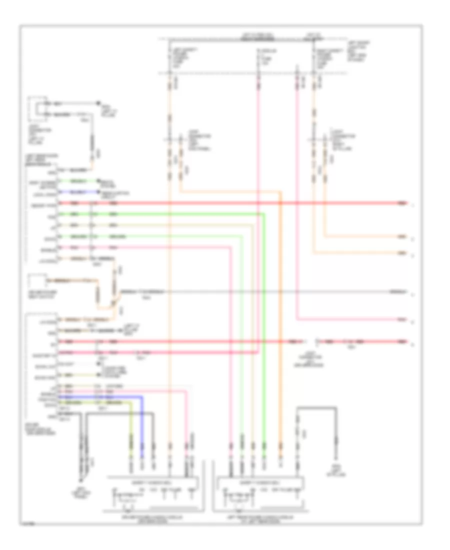 https://portal-diagnostov.com/license.html
Automotive Electricians Portal FZCO
Automotive Electricians Portal FZCO
https://portal-diagnostov.com/license.html
https://portal-diagnostov.com/license.html
Automotive Electricians Portal FZCO
Automotive Electricians Portal FZCOList of elements for Power Windows Wiring Diagram (1 of 2) for Hyundai Equus Ultimate 2014:
- (driver's door)
- (left "c" pillar) gf03
- (left rear door) left rear door module
- B-can high
- B-can low
- Circuit
- Computer data lines system
- D51-a
- D51-c
- Dd11
- Dd31
- Dir
- Down
- Driver door module
- Driver power seat switch
- Driver power window module (driver's door)
- Easy access led pwr
- Enable
- Fd11
- Fd21
- Fd31
- Fd41
- Gf01 (left kick panel)
- Gf02 (left "b" pillar)
- Gf03 (left "c" pillar)
- Gnd
- Hot at all times
- Hot w/ pdm (ig1) relay energized
- I/p-lha
- I/p-lhc
- Joint connector jd11 (driver's door)
- Joint connector jf01 (left "c" pillar)
- Joint connector jf03 (left kick panel)
- Joint connector jf13 (right "b" pillar)
- Left rear power window module (at left rear door)
- Left safety power window fuse 30a
- Left smart junction box (left end of dash)
- Lin comm
- Local comm
- Memory pwr
- Module fuse 10a
- On/start in
- Pnk
- Pos
- Position
- Pulse
- Rear curtain
- Red
- Right safety power window fuse 30a
- Safety window ecu
- Seats
- System
- Vcc
Power Windows Wiring Diagram (2 of 2) for Hyundai Equus Ultimate 2014
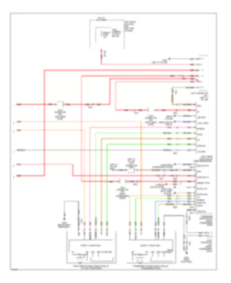 https://portal-diagnostov.com/license.html
Automotive Electricians Portal FZCO
Automotive Electricians Portal FZCO
https://portal-diagnostov.com/license.html
https://portal-diagnostov.com/license.html
Automotive Electricians Portal FZCO
Automotive Electricians Portal FZCOList of elements for Power Windows Wiring Diagram (2 of 2) for Hyundai Equus Ultimate 2014:
- (left "c" pillar) gf03
- (left "c" pillar) joint connector jf01
- (right rear door)
- B-can high
- B-can low
- D61-a
- D61-b
- D61-c
- Dd21
- Dd41
- Dir
- Down
- Ecs output
- Electronic suspension system
- Enable
- Fd21
- Fd31
- Fd41
- Gf03 (left "c" pillar)
- Gf05 (right kick panel)
- Gf09 (behind right rear seat)
- Gnd
- Gnd pwr
- Hot at all times
- I/p-lhc
- Interior lights system
- Joint connector jd21 (front passenger's door)
- Joint connector jd31 (left rear door)
- Joint connector jd41 (right rear door)
- Joint connector jf01 (left "c" pillar)
- Leak current autocut device
- Led pwr
- Left smart junction box (left end of dash)
- Lin comm
- Local comm
- Memory fuse 10a
- Memory pwr
- On/start in
- Passenger door module (front passenger's door)
- Passenger power window module (passenger's door)
- Pnk
- Pos
- Position
- Pulse
- Rear curtain circuit
- Red
- Right rear door module
- Right rear power window module (at right rear door)
- Safety window ecu
- Seats system
- Sens gnd
- Vcc
Rear Curtain Wiring Diagram for Hyundai Equus Ultimate 2014
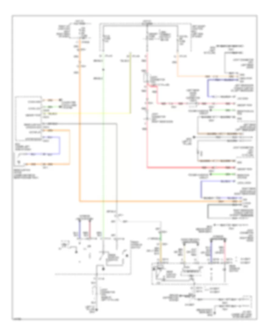 https://portal-diagnostov.com/license.html
Automotive Electricians Portal FZCO
Automotive Electricians Portal FZCO
https://portal-diagnostov.com/license.html
https://portal-diagnostov.com/license.html
Automotive Electricians Portal FZCO
Automotive Electricians Portal FZCOList of elements for Rear Curtain Wiring Diagram for Hyundai Equus Ultimate 2014:
- (behind right rear seat) gf08
- (left "c" pillar) gf03
- (left rear door) joint connector jd31
- 12v
- 5:5 seat
- 6:4 seat
- B-can ic
- Bcm (under left side of dash)
- C-can high
- C-can low
- Computer data lines system
- Cpu
- Dd31
- Dd41
- F/lid fuse 10a
- F11-a
- F11-b
- Fd31
- Fd41
- Fet
- Front console switch
- Fs31
- Fs41
- Gf02 (left "b" pillar)
- Gf03 (left "c" pillar)
- Gf09 (behind right rear seat)
- Gnd
- Ground distribution system
- High
- Hot at all times
- I/p-lhc
- I/p-lhg
- I/p-rhe
- Ill
- Interior lights system
- J/c js31 (under left side of driver seat)
- Joint connector jd31 (left rear door)
- Joint connector jd41 (right rear door)
- Joint connector jf01 (left "c" pillar)
- Joint connector jf02 (base of left "c" pillar)
- Leak current autocut device
- Left rear door module (left rear door)
- Left rear door window curtain (in left rear door)
- Left smart junction box (left end of dash)
- Loc comm
- Local comm
- Low
- M pwr gnd
- M32-a
- M32-b
- M32-c
- Memo pwr sig
- Memory fuse 10a
- Memory pwr
- Mf11
- Mf21
- Motor down
- Motor up
- O/s hdl rr fuse 15a
- Power windows circuit
- Rear console switch
- Rear curtain motor (under center of rear package tray)
- Rear curtain switch
- Rear curtain up/down sw
- Rear pwr win pos
- Red
- Right i/p junction box (right end of dash)
- Right rear door module (right rear door)
- Right rear door window curtain (in right rear door)
- S27-a
- S27-b
- S37-a
- S37-b
- Sig
- Ss31
- Ss41
RADIO
Radio Wiring Diagram (1 of 6) for Hyundai Equus Ultimate 2014
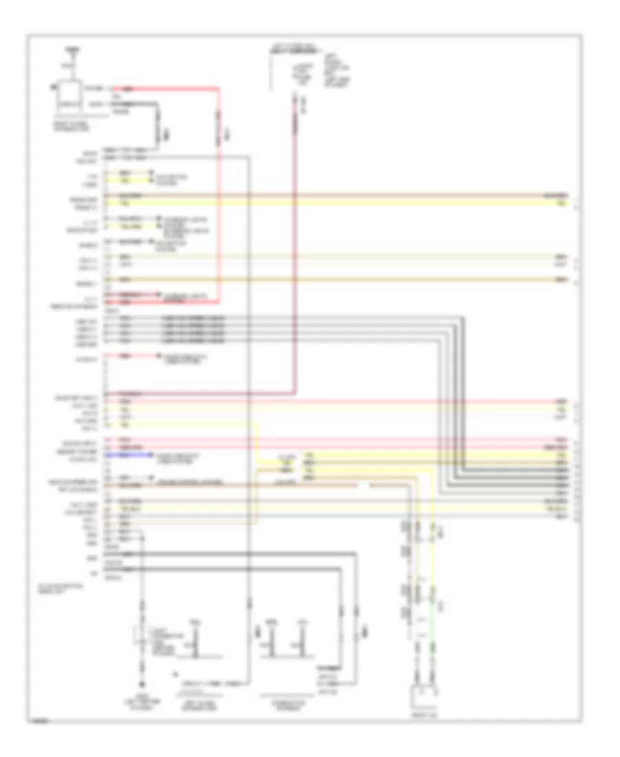 https://portal-diagnostov.com/license.html
Automotive Electricians Portal FZCO
Automotive Electricians Portal FZCO
https://portal-diagnostov.com/license.html
https://portal-diagnostov.com/license.html
Automotive Electricians Portal FZCO
Automotive Electricians Portal FZCOList of elements for Radio Wiring Diagram (1 of 6) for Hyundai Equus Ultimate 2014:
- (+)
- (-)
- (usb high speed cable)
- A/v & navigation head unit
- Acc/on input
- Am/fm
- Anfgr
- Ant-cg
- Ant-cx
- Audio (ig1) fuse 10a
- Aux detect
- Aux gnd
- Aux l
- Aux r
- Aux v gnd
- Aux v sig
- Backup sig
- Circuit
- Combination antenna
- Computer data lines system
- Cruise control system
- F04
- Fm2
- Fm2 ant
- Fr11
- Front mic
- Frt mic shield
- Gm03 (left center of dash)
- Gnd
- Gps
- Hot w/ pdm (ig1) relay energized
- I/p-lhg
- Ill (+)
- Ill (-)
- Interior lights system
- Interior lights system exterior lights system
- Joint connector jm05 (center of dash)
- Left glass antenna amp
- Left smart junction box (left end of dash)
- M-can hi
- M-can low
- M03-a
- M03-b
- M03-cg
- M03-cx
- Memory power
- Mf11
- Mf21
- Mic (+)
- Mic (-)
- Mm21
- Mm31
- Navi (+)
- Navi (-)
- Navigation system
- Nca
- On/start input
- Pnk
- Power
- Red
- Remote antenna
- Right glass antenna amp
- Rs485 (+)
- Rs485 (-)
- Rs485 gnd
- Shield
- Usb d (+)
- Usb d (-)
- Usb gnd
- Usb vcc
- V-gnd
- V-in
- Vehicle speed sig
- W/ mts
- W/o mts
Radio Wiring Diagram (2 of 6) for Hyundai Equus Ultimate 2014
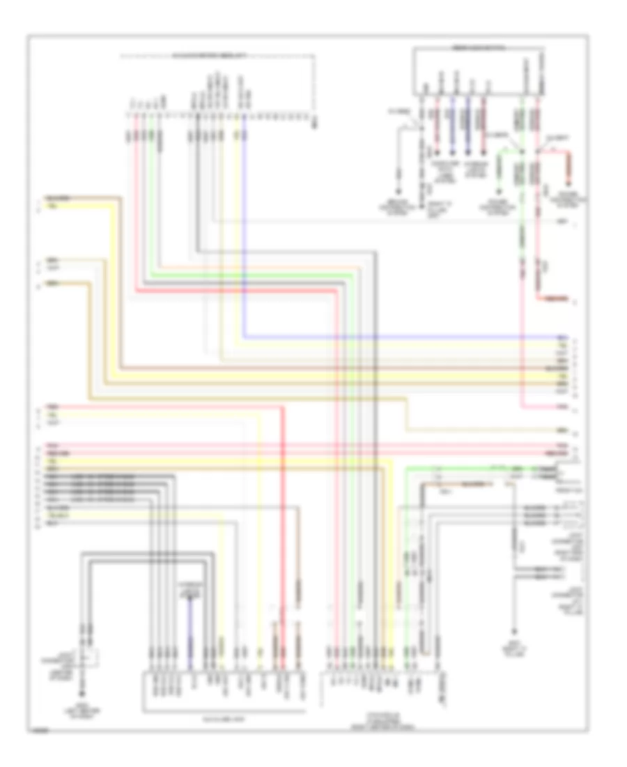 https://portal-diagnostov.com/license.html
Automotive Electricians Portal FZCO
Automotive Electricians Portal FZCO
https://portal-diagnostov.com/license.html
https://portal-diagnostov.com/license.html
Automotive Electricians Portal FZCO
Automotive Electricians Portal FZCOList of elements for Radio Wiring Diagram (2 of 6) for Hyundai Equus Ultimate 2014:
- (right "c" pillar) gf07
- (usb high speed cable)
- 6:4 seat
- A/v & navigation head unit
- Acc/on input
- Aux & usb jack
- Aux det
- Aux gnd
- Aux l
- Aux r
- Aux v sig
- Aux vgnd
- Computer data lines system
- Fr mic +
- Fr mic -
- Fr11
- Front mic
- Frt b/l on/off
- Fs31
- Gf07 (right "c" pillar)
- Gm03 (left center of dash)
- Gnd
- Ground distribution system
- Ill (+)
- Ill (-)
- Interior lights system
- Joint connector jf11 (right "c" pillar)
- Joint connector jm05 (center of dash)
- Joint connector jm07 (right end of dash)
- Lh rr on/off
- M-can hi
- M-can lo
- M03-c
- Memory power
- Mf11
- Mic +
- Mic -
- Mic shield
- Mts (+)
- Mts (-)
- Mts module (if equipped) (right center of dash)
- Nca
- Nca (+)
- Nca (-)
- Pnk
- Power distribution system
- Rear audio switch
- Red
- Rh rr on/off
- Rr lock det
- Rr pnd
- Rx +
- Rx -
- Sgnd
- Shield
- Ss31
- Tx +
- Tx -
- Usb d (+)
- Usb d (-)
- Usb gnd
- Usb vcc
Radio Wiring Diagram (3 of 6) for Hyundai Equus Ultimate 2014
 https://portal-diagnostov.com/license.html
Automotive Electricians Portal FZCO
Automotive Electricians Portal FZCO
https://portal-diagnostov.com/license.html
https://portal-diagnostov.com/license.html
Automotive Electricians Portal FZCO
Automotive Electricians Portal FZCOList of elements for Radio Wiring Diagram (3 of 6) for Hyundai Equus Ultimate 2014:
- (center of dash) joint connector jm05
- (left center of dash) gm03
- (left center side of dash) gm03
- Acc/on input
- Computer data lines system
- Front dis switch (center of floor console)
- Front monitor
- Frt b/l on/off
- Gf07 (right "c" pillar)
- Gm03 (left center of dash)
- Gnd
- Hot at all times
- I/p-lhc
- I/p-lhg
- Ill +
- Ill -
- Interior lights system
- Joint connector jf11 (right "c" pillar)
- Joint connector jm05 (center of dash)
- Left smart junction box (left end of dash)
- Lh rr on/off
- M-can hi
- M-can lo
- M25g
- M25h
- Memory power
- Memory pwr
- Mf11
- Multi media fuse 15a
- Pnk
- Red
- Rh rr on/off
- Rr lock det
- Rr pnd
- Split unit (under center floor console)
Radio Wiring Diagram (4 of 6) for Hyundai Equus Ultimate 2014
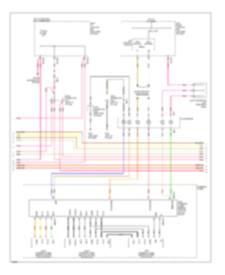 https://portal-diagnostov.com/license.html
Automotive Electricians Portal FZCO
Automotive Electricians Portal FZCO
https://portal-diagnostov.com/license.html
https://portal-diagnostov.com/license.html
Automotive Electricians Portal FZCO
Automotive Electricians Portal FZCOList of elements for Radio Wiring Diagram (4 of 6) for Hyundai Equus Ultimate 2014:
- Agnd
- Audio fuse 10a
- B-can
- B-can high
- B-can low
- Can hi
- Can lo
- Clockspring
- Computer data lines system
- Gf03 (left "c" pillar)
- Gm01 (left end of dash)
- Gnd
- Hot at all times
- Hot w/ pdm (acc) relay energized
- I/p-lhf
- I/p-rhd
- I/p-rhe
- Ill (+)
- Ill (-)
- Ips 3 (1ch)
- Ips 3 control
- Ips control module
- Joint connector jf01 (left "c" pillar)
- Joint connector jf11 (right "c" pillar)
- Joint connector jm01 (center of dash)
- Joint connector jm03 (right end of dash)
- Left smart junction box (left end of dash)
- Left steering wheel remote control switch (down)
- Left steering wheel remote control switch (up)
- M13
- M91
- M93-dl1
- M93-dl2
- Mem pwr
- Mf11
- Mf21
- Nca
- Pnk
- Power distribution system
- Red
- Right i/p junction box (right end of dash)
- Right steering wheel remote control switch (down)
- Right steering wheel remote control switch (up)
- Sig 1
- Sig 2
- Sig 3
- Steering wheel
Radio Wiring Diagram (5 of 6) for Hyundai Equus Ultimate 2014
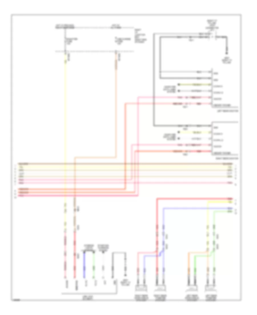 https://portal-diagnostov.com/license.html
Automotive Electricians Portal FZCO
Automotive Electricians Portal FZCO
https://portal-diagnostov.com/license.html
https://portal-diagnostov.com/license.html
Automotive Electricians Portal FZCO
Automotive Electricians Portal FZCOList of elements for Radio Wiring Diagram (5 of 6) for Hyundai Equus Ultimate 2014:
- (right "c" pillar) joint connector jf11
- Acc/on
- Alt
- Computer data lines system
- Dd31
- E-shifter fuse 10a
- Fd31
- Fd41
- Fs11
- Fs21
- Fs31
- Gf07 (right "c" pillar)
- Gnd
- Hot at all times
- Hot w/ pdm (acc) relay energized
- I/p-rhd
- I/p-rhe
- Ill (+)
- Ill (-)
- Interior lights system
- Left rear door middle speaker
- Left rear monitor
- Left rear tweeter speaker
- M-can hi
- M-can lo
- Mem pwr
- Memory power
- Mf21
- Nca
- Pnk
- Red
- Right i/p junction box (right end of dash)
- Right rear door middle speaker
- Right rear monitor
- Right rear tweeter speaker
- Ss31
- Starting/ charging system
- Usb charge fuse 10a
- Usb jack (6:4 seat)
Radio Wiring Diagram (6 of 6) for Hyundai Equus Ultimate 2014
 https://portal-diagnostov.com/license.html
Automotive Electricians Portal FZCO
Automotive Electricians Portal FZCO
https://portal-diagnostov.com/license.html
https://portal-diagnostov.com/license.html
Automotive Electricians Portal FZCO
Automotive Electricians Portal FZCOList of elements for Radio Wiring Diagram (6 of 6) for Hyundai Equus Ultimate 2014:
- (+)
- (-)
- (right "c" pillar) gf07
- Acc/on input
- Amp (right side of trunk)
- Amp fuse 30a
- Center (+)
- Center (-)
- Center speaker
- Computer data lines system
- Dd11
- Dd21
- Driver door middle speaker
- Driver door speaker
- Driver tweeter speaker
- E/r fuse & relay box (left side of engine compt)
- Ef21
- F03-a
- F03-b
- F03-c
- Fd11
- Fd21
- Fd31
- Fd41
- Ff01
- Fl (+)
- Fl (-)
- Fr (+)
- Fr (-)
- Gnd
- Hot at all times
- Left deck speaker
- Left rear door speaker
- Lh (+)
- Lh (-)
- M-can hi
- M-can lo
- Mem pwr
- Mf21
- Navi (+)
- Navi (-)
- Nca
- Passenger door middle speaker
- Passenger door speaker
- Passenger tweeter speaker
- Pnk
- Red
- Rh (+)
- Rh (-)
- Right deck speaker
- Right rear door speaker
- Rl (+)
- Rl (-)
- Rr (+)
- Rr (-)
- Spdif (+)
- Spdif (-)
- Spdif shield
- Sub 1 (+)
- Sub 1 (-)
- Sub 2 (+)
- Sub 2 (-)
- Sub woofer
SHIFT INTERLOCK
Electric Parking Brake Wiring Diagram for Hyundai Equus Ultimate 2014
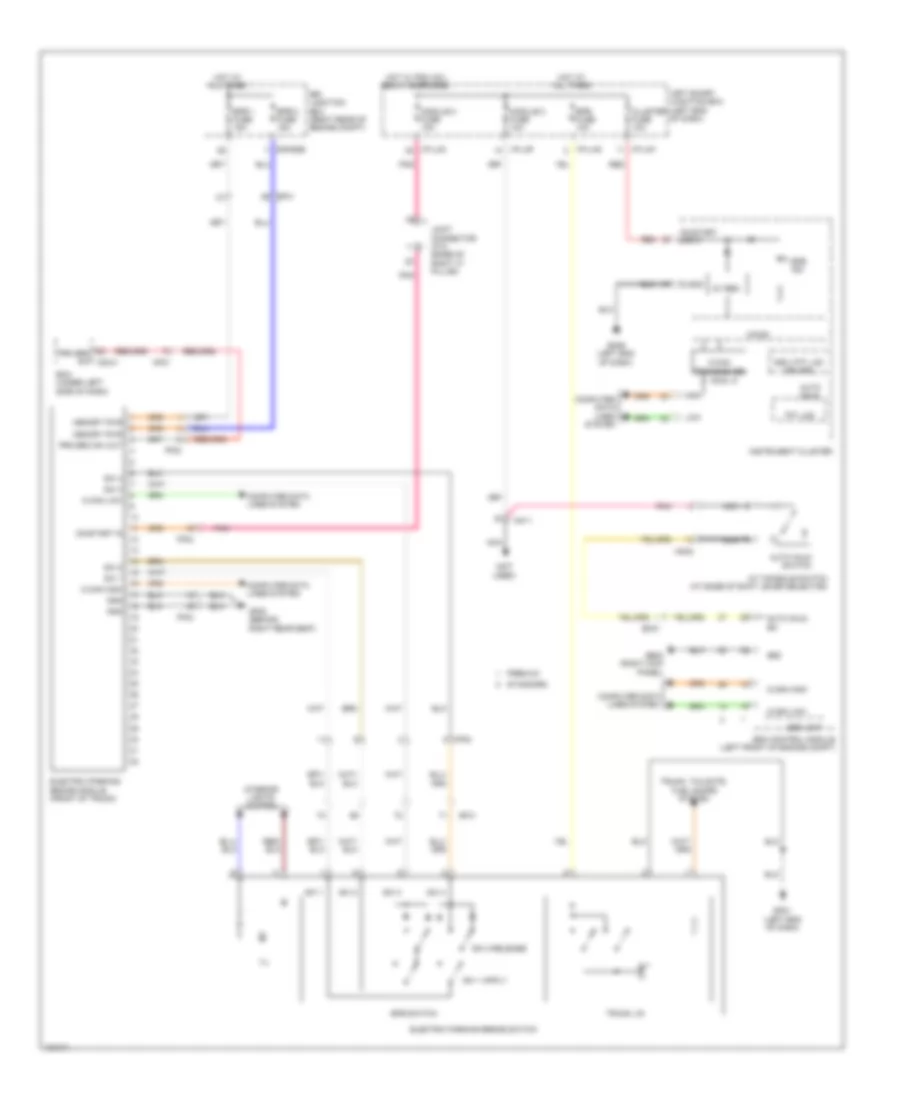 https://portal-diagnostov.com/license.html
Automotive Electricians Portal FZCO
Automotive Electricians Portal FZCO
https://portal-diagnostov.com/license.html
https://portal-diagnostov.com/license.html
Automotive Electricians Portal FZCO
Automotive Electricians Portal FZCOList of elements for Electric Parking Brake Wiring Diagram for Hyundai Equus Ultimate 2014:
- (not used)
- 5v reg
- A/t console switch (at base of shift lever selector)
- Auto hold
- Auto hold sw
- Auto hold switch
- Bcm (under left side of dash)
- C-can high
- C-can low
- C-can transceiver
- Cluster fuse 10a
- Computer data lines system
- E/r junction box (right rear of engine compt)
- E/r-e2b
- Ef31
- Electric parking brake module (front of trunk)
- Electric parking brake switch
- Em31
- Epb 1 fuse 15a
- Epb 2 fuse 15a
- Epb fuse 10a
- Epb ind
- Epb switch
- Esc control module (left front of engine compt)
- Esc unit
- Ff02
- Gdc (tft lcd driver)
- Ge02 (right kick panel)
- Gf08 (behind right rear seat)
- Gm01 (left end of dash)
- Gm06 (left end of dash)
- Gnd
- High
- Hot at all times
- Hot w/ pdm (ig1) relay energized
- I/p-lhc
- I/p-lhf
- I/p-lhg
- Ill
- Instrument cluster
- Interior lights system
- Joint connector jf12 (base of right "c" pillar)
- Left smart junction box (left end of dash)
- Low
- Memory pwr
- Mf21
- Micom
- Mm02
- Mm11
- Module 2 fuse 10a
- Module 3 fuse 10a
- Nca
- On/start in
- On/start input
- Pnk
- Premium
- Prk brk sw m32-a
- Prk brk sw out
- Red
- S gnd
- Standard
- Sw 1
- Sw 2
- Sw 2 release
- Sw 3
- Sw 4
- Tft lcd
- Trunk lid
- Trunk, tailgate, fuel doors system
Shift Interlock Wiring Diagram for Hyundai Equus Ultimate 2014
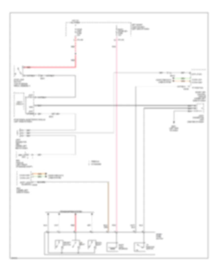 https://portal-diagnostov.com/license.html
Automotive Electricians Portal FZCO
Automotive Electricians Portal FZCO
https://portal-diagnostov.com/license.html
https://portal-diagnostov.com/license.html
Automotive Electricians Portal FZCO
Automotive Electricians Portal FZCOList of elements for Shift Interlock Wiring Diagram for Hyundai Equus Ultimate 2014:
- "p" position
- "p" position switch
- Bcm (under left side of dash)
- Brk lp sw
- C-can high
- C-can low
- Computer data lines system
- Down shift
- Em-31
- Em31
- Esc module (left front of engine compt)
- Gm01 (left end of dash)
- Gnd
- Hot at all times
- I/p-lhe
- I/p-lhg
- Input circuit
- Joint connector je02 (under left end of dash)
- Joint connector jm05 (center of dash)
- Left smart junction box (left end of dash)
- M30-b
- Pnk
- Premium
- Red
- Select switch
- Shift lever (b+) fuse 10a
- Shift lock solenoid
- Shift lock solenoid m32-b
- Smart key control module (under left side of dash)
- Sport mode switch
- Standard
- Stop lamp fuse 10a
- Stop lamp switch (top of brake pedal assembly)
- Stop signal electronic module (left side of dash)
- Stp lp sig
- Stp lp sw
- Transmissions system
- Up shift
STARTING/CHARGING
Charging Wiring Diagram for Hyundai Equus Ultimate 2014
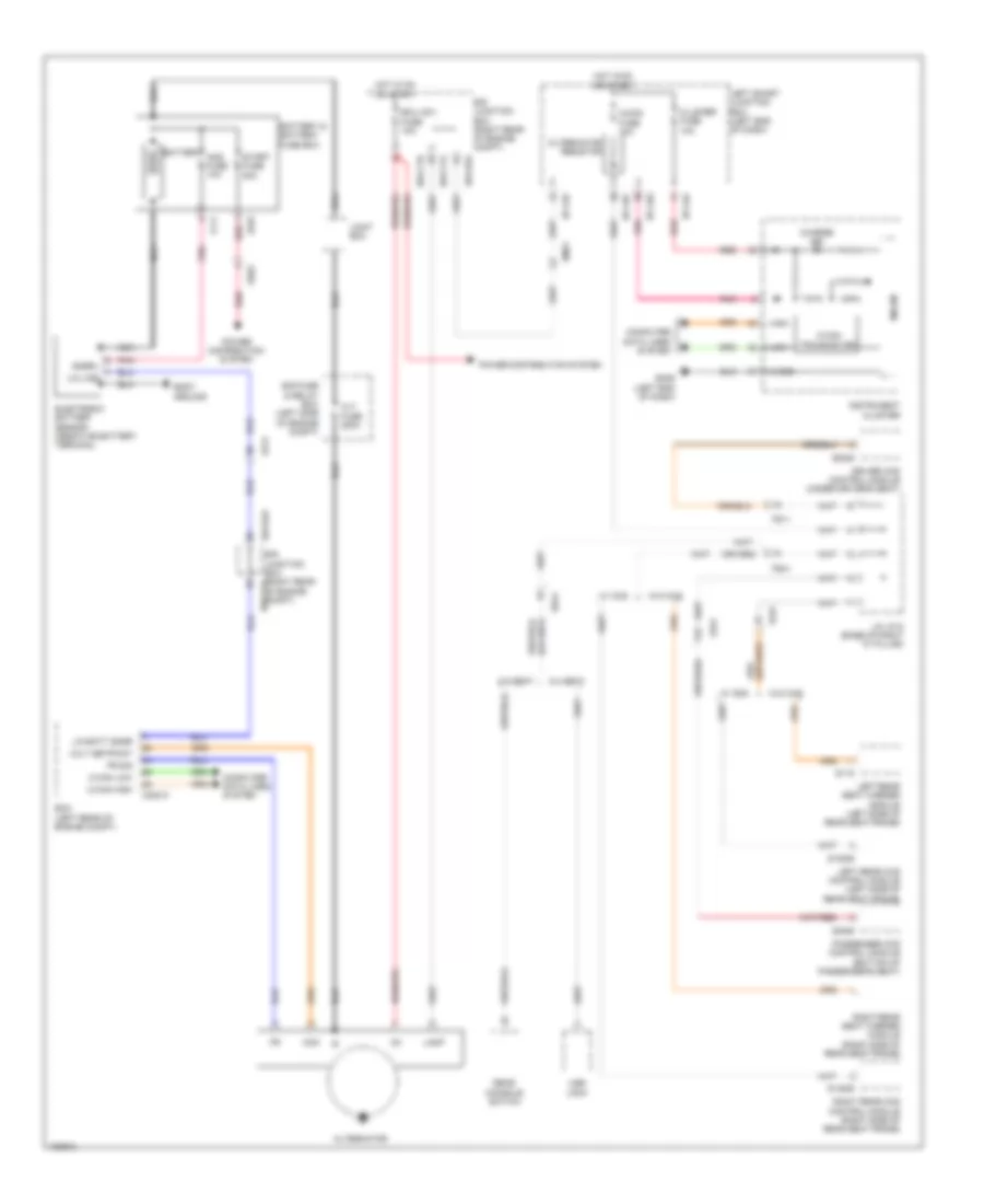 https://portal-diagnostov.com/license.html
Automotive Electricians Portal FZCO
Automotive Electricians Portal FZCO
https://portal-diagnostov.com/license.html
https://portal-diagnostov.com/license.html
Automotive Electricians Portal FZCO
Automotive Electricians Portal FZCOList of elements for Charging Wiring Diagram for Hyundai Equus Ultimate 2014:
- 5:5 seat
- 6:4 seat
- A/con fuse 10a
- Alt fuse 200a
- Alternator
- Alternator resistor
- Ams fuse 10a
- Battery
- Battery & battery fuse box
- Body ground
- C-can high
- C-can low
- C-can transceiver
- C200-k
- Charge ind
- Cluster fuse 10a
- Com
- Computer data lines system
- Driver ccs control module (under driver's seat)
- E/r fuse & relay box (left side of engine compt)
- E/r junction box (right rear e/r-cta of engine compt)
- E/r junction box (right rear of engine compt)
- E/r-cta
- E/r-ctb
- E/r-e2a
- Ecm (left rear of engine compt)
- Ecu (ig1) fuse 10a
- Ee01
- Ef01
- Ef21
- Em21
- Ff11
- Fr sig
- Fs11
- Fs21
- Fs31
- Fs41
- Gm06 (left end of dash)
- High
- Hot in on or start
- I/p-lhc
- I/p-lhf
- I/p-lhg
- Ig1
- Instrument cluster
- J/c jf12 (base of right "c" pillar)
- Joint box
- Lamp
- Left rear ccs control module (left side of rear seat frame)
- Left rear seat warmer module (left side of rear seat frame)
- Left smart junction box (left end of dash)
- Lin batt snsr
- Lin line
- Low
- Micom
- Nca
- Passenger ccs control module (bottom of passenger's seat)
- Pnk
- Power distribution system
- Rear console switch
- Red
- Right rear ccs control module (right side of rear seat frame)
- Right rear seat warmer module (right side of rear seat frame)
- S-gnd
- S06-b
- S106-b
- S115
- S146-b
- S46-b
- Snsr+
- Ss41
- Start fuse 50a
- Usb jack
- Volt setpoint
- W/ ccs
- W/o ccs
Starting Wiring Diagram for Hyundai Equus Ultimate 2014
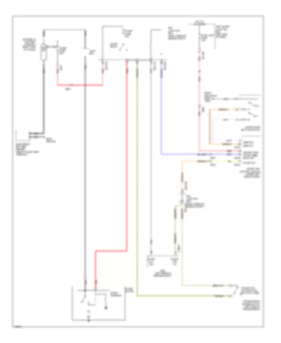 https://portal-diagnostov.com/license.html
Automotive Electricians Portal FZCO
Automotive Electricians Portal FZCO
https://portal-diagnostov.com/license.html
https://portal-diagnostov.com/license.html
Automotive Electricians Portal FZCO
Automotive Electricians Portal FZCOList of elements for Starting Wiring Diagram for Hyundai Equus Ultimate 2014:
- (right center of dash)
- Battery
- Battery & battery fuse box (right side of trunk)
- Body ground
- C200-k
- E/r junction box (right rear of e/r-ctb
- E/r junction box (right rear of engine compt)
- E/r-cta
- E/r-e1a
- E/r-e2a
- E/r-e2b
- Ecm (left rear of engine compt)
- Ee01
- Ef01
- Em31
- Em41
- Engine compt)
- Gm04
- Hot at all times
- I/p-lhe
- Joint box
- Left smart junction box (left end of dash)
- M30-a
- M30-b
- Memory pwr start feed/ back sig
- Nca
- P/n switch (p/n position switch close)
- Red
- Smart key control module (under left side of dash)
- Ssb sw1
- Ssb sw2
- Start fuse 30a
- Start fuse 50a
- Start motor
- Start relay
- Start rly
- Start rly o/p
- Start sig i/p
- Start solenoid
- Start/stop button switch
- Stop lamp fuse 10a
- Transmission range switch (left side of transmission)
SUPPLEMENTAL RESTRAINTS
Air Bag Wiring Diagram (1 of 3) for Hyundai Equus Ultimate 2014
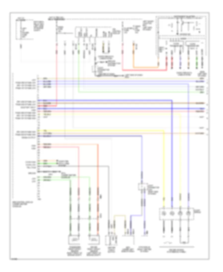 https://portal-diagnostov.com/license.html
Automotive Electricians Portal FZCO
Automotive Electricians Portal FZCO
https://portal-diagnostov.com/license.html
https://portal-diagnostov.com/license.html
Automotive Electricians Portal FZCO
Automotive Electricians Portal FZCOList of elements for Air Bag Wiring Diagram (1 of 3) for Hyundai Equus Ultimate 2014:
- (left end of dash) gm01
- A/bag fuse 15a
- A/bag ind fuse 10a
- Air bag ind
- Bcm (under left side of dash)
- C-can high
- C-can low
- C-can transceiver
- Center fascia switch
- Clock spring
- Cluster fuse 10a
- Computer data lines system
- Crash output
- Driver air bag (in steering wheel)
- Driver front impact sensor (left front of engine compt)
- Drv 1st stage high
- Drv 1st stage low
- Drv 2nd stage high
- Drv 2nd stage low
- E/r fuse & relay box (left side of engine compt)
- Ee21
- Em01
- Gf13 (under center console)
- Gm06 (left end of dash)
- Ground
- Ground distribution system
- High
- High b-can
- Hot at all times
- Hot w/ pdm (ig1) relay energized
- I/p-lhb
- I/p-lhd
- I/p-lhf
- Ign1
- Instrument cluster
- Ips control module
- Joint connector jm03 (right end of dash)
- Joint connector jm05 (center of dash)
- Left i/p power fuse 80a
- Left smart junction box (left end of dash)
- Low
- Low b-can
- M-can transceiver
- M06
- M32-a
- M32-b
- M53
- Mf01
- Micom
- Mts module (right center of dash)
- Nca
- On/start input
- Pass 1st stage high
- Pass 1st stage low
- Pass 2nd stage high
- Pass 2nd stage low
- Pass 3rd stage high
- Pass 3rd stage low
- Passenger front impact sensor (right front of engine compt)
- Pwr gnd
- Red
- S-gnd
- Sbr ind
- Seat belt ind
- Seat blt drv
- Seat blt pass
- Srs control module (under center console)
- Telltale
Air Bag Wiring Diagram (2 of 3) for Hyundai Equus Ultimate 2014
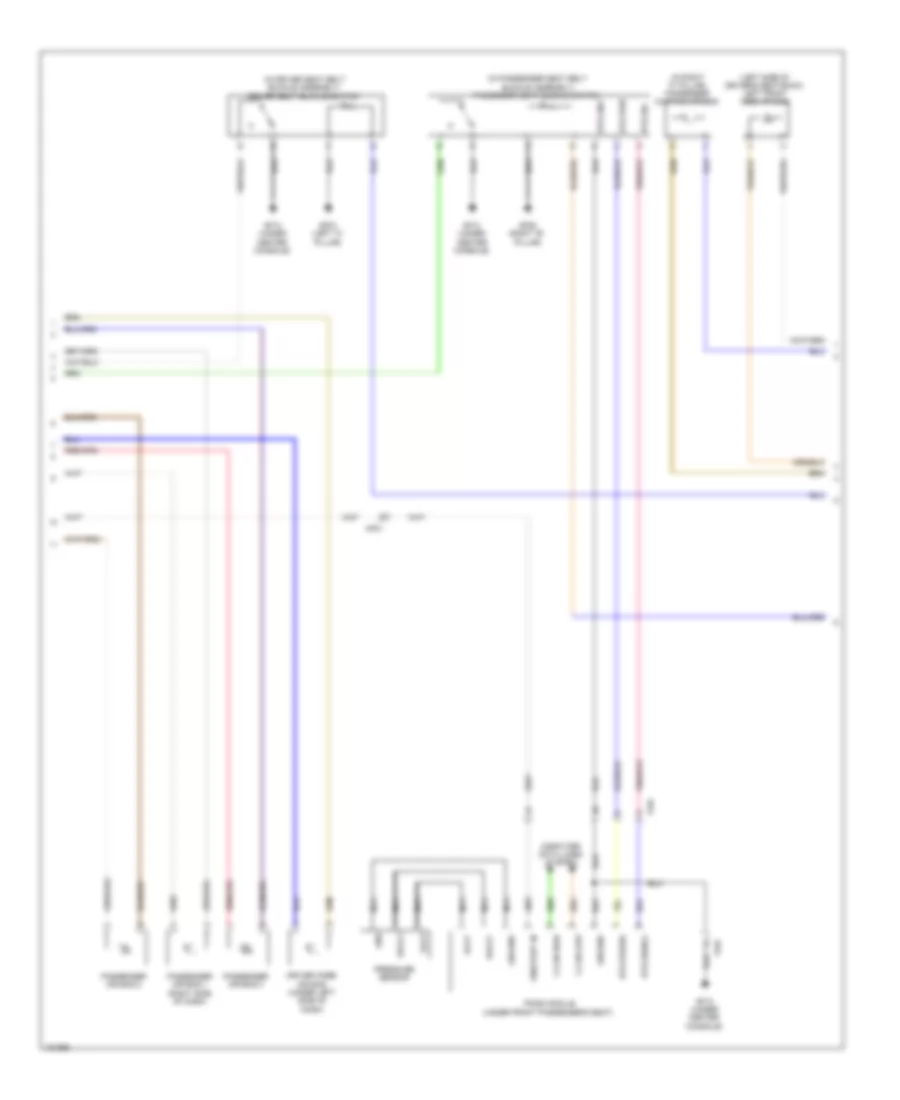 https://portal-diagnostov.com/license.html
Automotive Electricians Portal FZCO
Automotive Electricians Portal FZCO
https://portal-diagnostov.com/license.html
https://portal-diagnostov.com/license.html
Automotive Electricians Portal FZCO
Automotive Electricians Portal FZCOList of elements for Air Bag Wiring Diagram (2 of 3) for Hyundai Equus Ultimate 2014:
- (in driver seat belt buckle assembly) driver seat buckle switch
- (in passenger seat belt buckle assembly) passenger seat buckle switch
- (in right "c" pillar) passenger curtain air bag
- (left side of driver's seat back) left front side air bag
- Bts gnd
- Bts power
- Bts pwr
- Bts sig
- Bts signal
- C-can high
- C-can low
- Computer data lines system
- Driver knee air bag (under left side of dash)
- Ff04
- Gf03 (left "c" pillar)
- Gf06 (right "b" pillar)
- Gf13 (under center console)
- Gnd
- Ground
- Mf01
- Nca
- On/start in
- Passenger air bag 1 (right side of dash)
- Passenger air bag 2
- Passenger air bag 3
- Pods module (under front passenger's seat)
- Pressure sensor
- Svolt
- Vovt
Air Bag Wiring Diagram (3 of 3) for Hyundai Equus Ultimate 2014
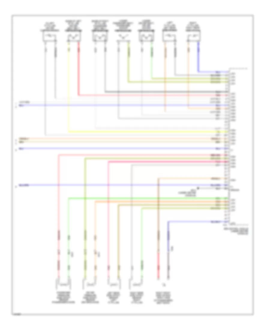 https://portal-diagnostov.com/license.html
Automotive Electricians Portal FZCO
Automotive Electricians Portal FZCO
https://portal-diagnostov.com/license.html
https://portal-diagnostov.com/license.html
Automotive Electricians Portal FZCO
Automotive Electricians Portal FZCOList of elements for Air Bag Wiring Diagram (3 of 3) for Hyundai Equus Ultimate 2014:
- (+)
- (base of left "b" pillar) driver seat belt pretensioner
- (base of right "b" pillar) passenger seat belt pretensioner
- (in left "c" pillar) driver curtain air bag
- (left "c" pillar) left rear side air bag
- (right "c" pillar) right rear side air bag
- (under driver seat) driver anchor pretensioner
- (under passenger seat) passenger anchor pretensioner
- Driver pressure side impact sensor (driver's door)
- F10
- Fd11
- Fd21
- Ff04
- Gf13 (under center console)
- Ground
- High
- Left rear side impact sensor (left "c" pillar)
- Low
- Passenger pressure side impact sensor (passenger's door)
- Pnk
- Red
- Right front side air bag (right side of passenger's seat back)
- Right rear side impact sensor (right "c" pillar)
- Srs control module (under center console)
Electronic Active Headrest Wiring Diagram for Hyundai Equus Ultimate 2014
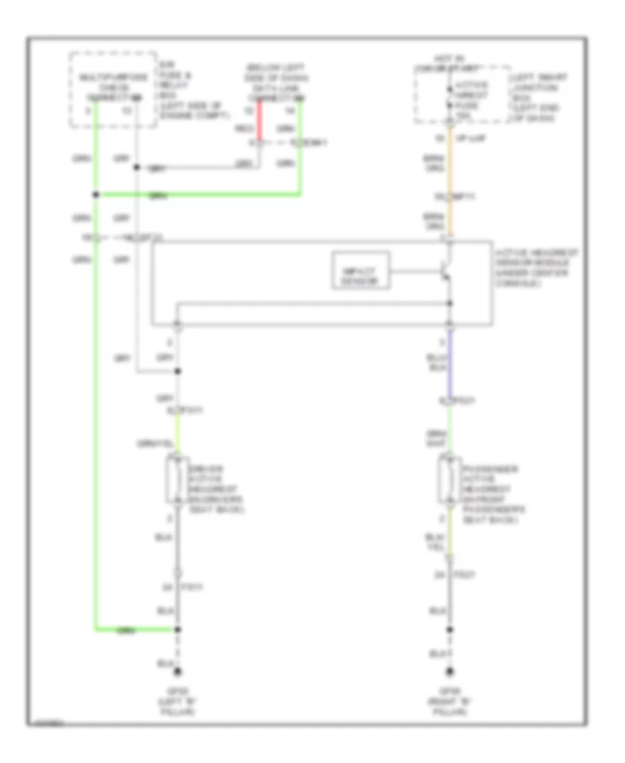 https://portal-diagnostov.com/license.html
Automotive Electricians Portal FZCO
Automotive Electricians Portal FZCO
https://portal-diagnostov.com/license.html
https://portal-diagnostov.com/license.html
Automotive Electricians Portal FZCO
Automotive Electricians Portal FZCOList of elements for Electronic Active Headrest Wiring Diagram for Hyundai Equus Ultimate 2014:
- (below left side of dash) data link connector
- Active h/rest fuse 10a
- Active headrest sensor module (under center console)
- Driver active headrest (in driver's seat back)
- E/r fuse & relay box (left side of engine compt)
- Ef31
- Em41
- Fs11
- Fs21
- Gf02 (left "b" pillar)
- Gf06 (right "b" pillar)
- Hot in on or start
- I/p-lhf
- Impact sensor
- Left smart junction box (left end of dash)
- Mf11
- Multipurpose check connector
- Passenger active headrest (in front passenger's seat back)
- Red
Pre-Safe Seat Belt Wiring Diagram for Hyundai Equus Ultimate 2014
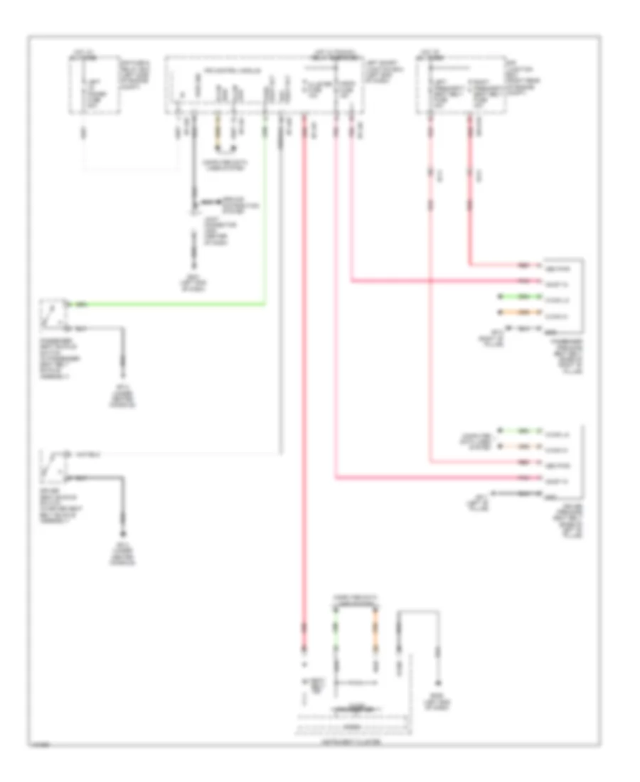 https://portal-diagnostov.com/license.html
Automotive Electricians Portal FZCO
Automotive Electricians Portal FZCO
https://portal-diagnostov.com/license.html
https://portal-diagnostov.com/license.html
Automotive Electricians Portal FZCO
Automotive Electricians Portal FZCOList of elements for Pre-Safe Seat Belt Wiring Diagram for Hyundai Equus Ultimate 2014:
- A/bag fuse 15a
- C-can
- C-can hi
- C-can lo
- Cluster fuse 10a
- Computer data lines system
- Driver pre-safe seat belt (base of left "b" pillar)
- Driver seat buckle switch (in driver seat belt buckle assembly)
- E/r fuse & relay box (left side of engine compt)
- E/r junction box (right rear of engine compt)
- E/r-e1b
- Ef11
- Ef21
- Gf11 (left "b" pillar)
- Gf12 (right "b" pillar)
- Gf13 (under center console)
- Gm01 (left end of dash)
- Gm06 (left end of dash)
- Gnd
- Ground distribution system
- High
- High b-can
- Hot at all times
- Hot w/ pcm(ig1) relay energized
- I/p-lhb
- I/p-lhc
- I/p-lhd
- I/p-lhf
- Instrument cluster
- Ips control module
- Joint connector jm05 (center of dash)
- Left i/p power fuse 80a
- Left presafety seat belt fuse 40a
- Left smart junction box (left end of dash)
- Low
- Low b-can
- Mem pwr
- Micom
- On/st in
- Passenger pre-safe seat belt (base of right "b" pillar)
- Passenger seat buckle switch (in passenger seat belt buckle assembly)
- Pnk
- Pwr gnd
- Red
- Right presafety seat belt fuse 40a
- S-gnd
- Seat belt ind
- Seat blt drv
- Seat blt pass
- Transceiver
TRANSMISSION
Transmission Wiring Diagram (1 of 3) for Hyundai Equus Ultimate 2014
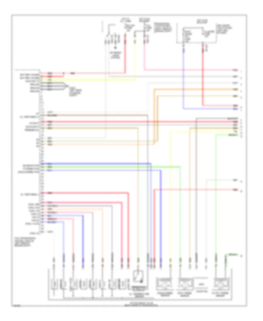 https://portal-diagnostov.com/license.html
Automotive Electricians Portal FZCO
Automotive Electricians Portal FZCO
https://portal-diagnostov.com/license.html
https://portal-diagnostov.com/license.html
Automotive Electricians Portal FZCO
Automotive Electricians Portal FZCOList of elements for Transmission Wiring Diagram (1 of 3) for Hyundai Equus Ultimate 2014:
- Atm solenoid valve (right rear of transmission)
- Battery power
- Cluster fuse 10a
- D-sol 27
- D-sol 35r
- D-sol 4 & od
- D-sol 6
- D-sol 8lr
- D-sol ud
- Down shift
- E/r-ctb
- E/r-e2b
- Ecu (b+) fuse 15a
- Engine room junction box (right rear of engine compt)
- Exterior lights system
- Gc201 (left rear of engine compt)
- Ground
- Hot at all times
- Hot in on or start
- I/p speed pwr
- I/p-lhf
- Input speed sensor
- Left smart junction box (left end of dash)
- Middle speed pwr
- Middle speed sensor
- Oil temp sens (+)
- Oil temp sens (-)
- Oil temperature sensor
- On/off sol
- On/start ip
- Output speed sensor
- Pnk
- Presser sw
- Pressure sw
- Red
- Shift lever (ig1) fuse 10a
- Solenoid pwr
- Tcm (transmission control module) (left rear of engine compt)
- Tcu fuse 15a
- Up shift
- Vfs dc
- Vfs lp
Transmission Wiring Diagram (2 of 3) for Hyundai Equus Ultimate 2014
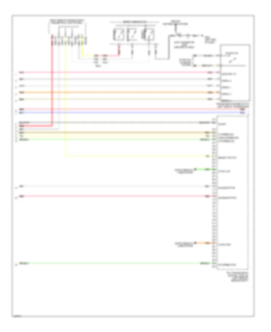 https://portal-diagnostov.com/license.html
Automotive Electricians Portal FZCO
Automotive Electricians Portal FZCO
https://portal-diagnostov.com/license.html
https://portal-diagnostov.com/license.html
Automotive Electricians Portal FZCO
Automotive Electricians Portal FZCOList of elements for Transmission Wiring Diagram (2 of 3) for Hyundai Equus Ultimate 2014:
- (right rear of engine compt) engine room junction box
- C-can high
- C-can low
- Computer data lines system
- Down shift
- E/r-cta
- E/r-ctb
- E/r-e2a
- E/r-e2b
- Em41
- Gm01 (left end of dash)
- Ground distribution system
- I/p speed sig
- Joint connector jm05 (center of dash)
- Middle speed sig
- O/p speed pwr
- O/p speed sig
- On/off
- On/start i/p
- P/n switch
- Pnk
- Red
- Select switch
- Signal 1
- Signal 2
- Signal 3
- Signal 4
- Solenoid pwr
- Solenoid pwr 2
- Sport mode switch
- Starting/ charging system
- Tcm (transmission control module) (left rear of engine compt)
- Transmission range switch (left side of transmission)
- Up shift
Transmission Wiring Diagram (3 of 3) for Hyundai Equus Ultimate 2014
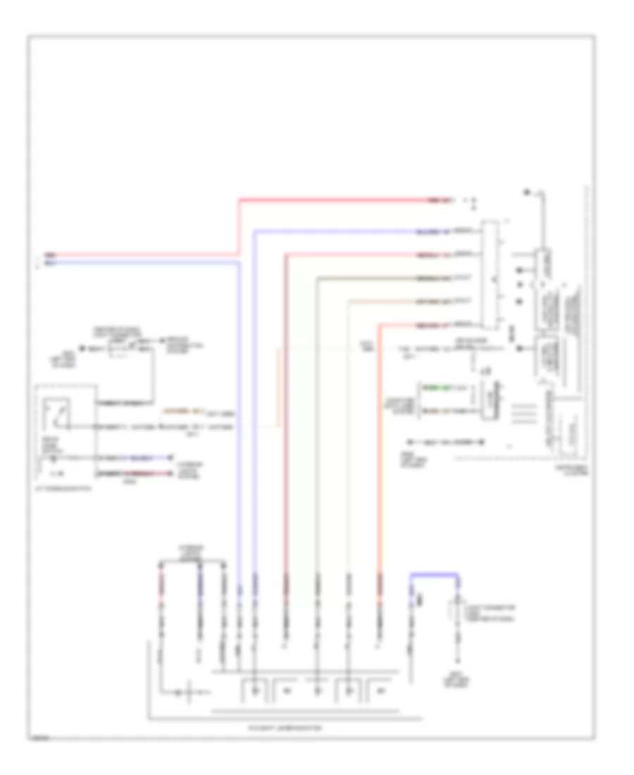 https://portal-diagnostov.com/license.html
Automotive Electricians Portal FZCO
Automotive Electricians Portal FZCO
https://portal-diagnostov.com/license.html
https://portal-diagnostov.com/license.html
Automotive Electricians Portal FZCO
Automotive Electricians Portal FZCOList of elements for Transmission Wiring Diagram (3 of 3) for Hyundai Equus Ultimate 2014:
- (center of dash) joint connector jm05
- (not used)
- +/-
- 1.5v/1.275v
- 1.8v reg (full tft lcd type)
- 3.3v reg
- 5w 5v
- A/t console switch
- Atm shift lever indicator
- C-can transceiver
- Computer data lines system
- D-out
- Detent
- Drive mode sw i/p
- Drive mode switch
- Gdc (tft lcd driver)
- Gm01 (left end of dash)
- Gm06 (left end of dash)
- Gnd
- Ground distribution system
- High
- I/f
- Ign1
- Ill
- Ill (+)
- Ill (-)
- Instrument cluster
- Interior lights system
- Joint connector jm05 (center of dash)
- Lcd type) (7 inch tft 1.2v reg
- Lcd type) reg (full tft
- Low
- Mf11
- Micom
- Mm02
- N-out
- Nca
- P-out
- R-out
- Red
- S-gnd
- S-out
- Tft lcd
TRUNK, TAILGATE, FUEL DOOR
Power Tailgate Wiring Diagram (1 of 2) for Hyundai Equus Ultimate 2014
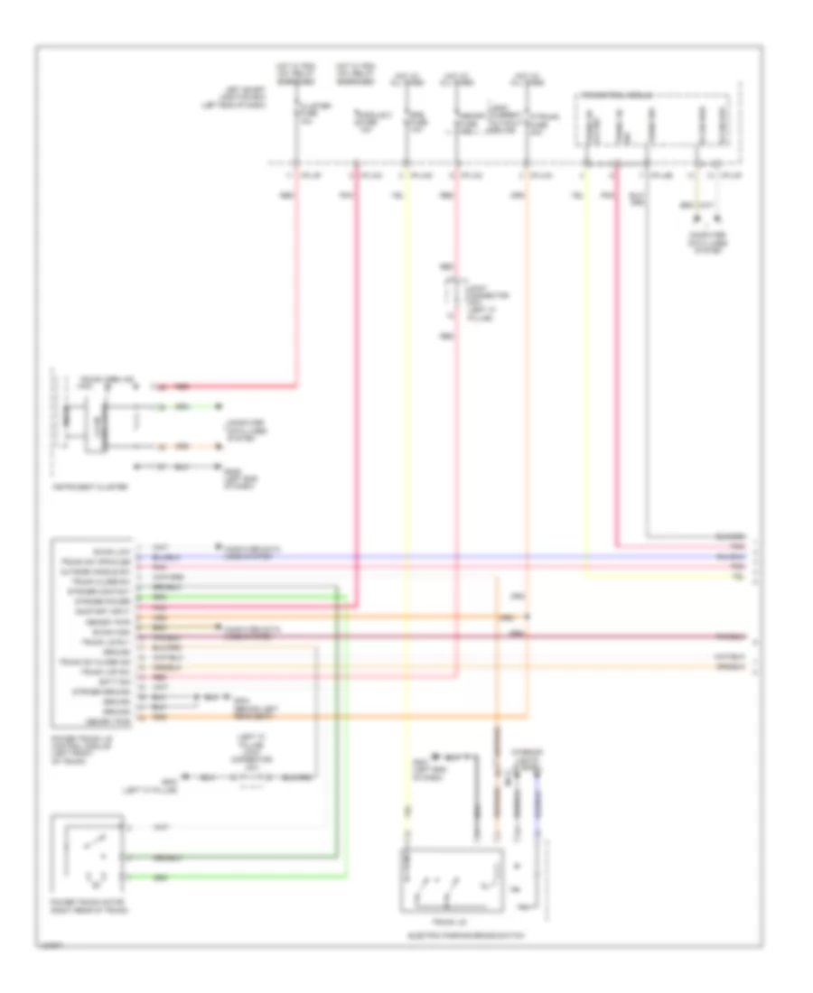 https://portal-diagnostov.com/license.html
Automotive Electricians Portal FZCO
Automotive Electricians Portal FZCO
https://portal-diagnostov.com/license.html
https://portal-diagnostov.com/license.html
Automotive Electricians Portal FZCO
Automotive Electricians Portal FZCOList of elements for Power Tailgate Wiring Diagram (1 of 2) for Hyundai Equus Ultimate 2014:
- (left "c" pillar) joint connector jf01
- B-can high
- B-can low
- B-can-low
- Batt sig
- Cluster fuse 10a
- Computer data lines system
- Electric parking brake switch
- Epb fuse 10a
- Gf03 (left "c" pillar)
- Gf04 (behind left rear seat)
- Gm01 (left end of dash)
- Gm06 (left end of dash)
- Ground
- Hot at all times
- Hot w/ pdm (ig1) relay energized
- I/p-lha
- I/p-lhb
- I/p-lhc
- I/p-lhf
- I/p-lhg
- Ill
- Instrument cluster
- Interior lights system
- Ips control module
- Joint connector jf01 (left "c" pillar)
- Leak current autocut device
- Left smart junction box (left end of dash)
- Memory fuse 10a
- Memory pwr
- Mf11
- Micom
- Module 2 fuse 10a
- On/start input
- Outside handle sw
- P/trunk fuse 30a
- Pnk
- Power trunk lid control module (left front of trunk)
- Power trunk motor (right rear of trunk)
- Red
- Striker contact
- Striker ground
- Striker power
- Transceiver c-can
- Trunk close sw
- Trunk dr lck sw
- Trunk lid
- Trunk lid rly
- Trunk lid sw
- Trunk lmp sw
- Trunk open ind
- Trunk sw
- Trunk sw close ind
- Trunk sw opn/clse
Power Tailgate Wiring Diagram (2 of 2) for Hyundai Equus Ultimate 2014
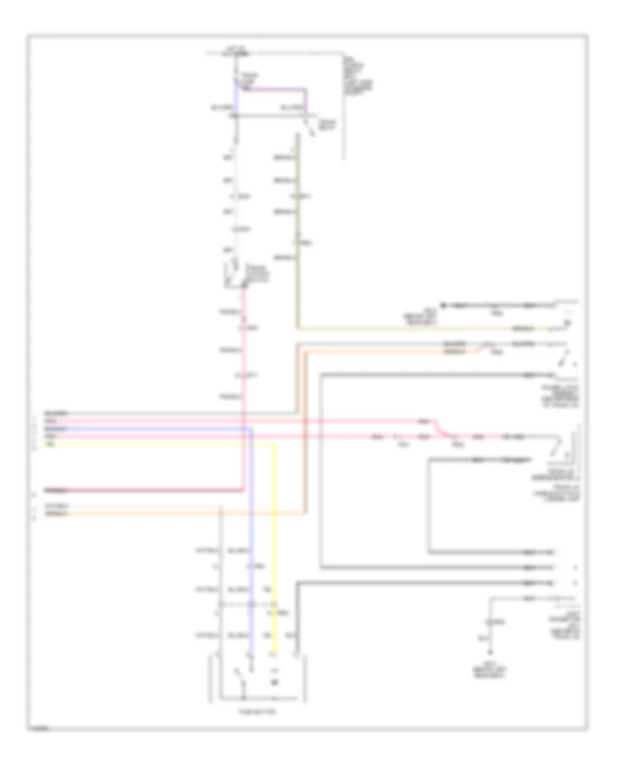 https://portal-diagnostov.com/license.html
Automotive Electricians Portal FZCO
Automotive Electricians Portal FZCO
https://portal-diagnostov.com/license.html
https://portal-diagnostov.com/license.html
Automotive Electricians Portal FZCO
Automotive Electricians Portal FZCOList of elements for Power Tailgate Wiring Diagram (2 of 2) for Hyundai Equus Ultimate 2014:
- (behind left rear seat)
- E/r fuse & relay box (left side of engine compt)
- Ef11
- Em21
- Ff01
- Fr01
- Fr02
- Gf10
- Gf10 (behind left rear seat)
- Hot at all times
- Joint connector jr11 (center of trunk lid)
- Mf11
- Mm01
- Nca
- Pnk
- Power latch assembly (center rear of trunk lid)
- Push button
- Trunk fuse 10a
- Trunk lid handle switch
- Trunk lid handle switch & license lamp
- Trunk lid main switch
- Trunk relay
Trunk & Fuel Door Release Wiring Diagram for Hyundai Equus Ultimate 2014
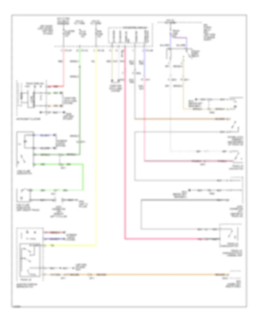 https://portal-diagnostov.com/license.html
Automotive Electricians Portal FZCO
Automotive Electricians Portal FZCO
https://portal-diagnostov.com/license.html
https://portal-diagnostov.com/license.html
Automotive Electricians Portal FZCO
Automotive Electricians Portal FZCOList of elements for Trunk & Fuel Door Release Wiring Diagram for Hyundai Equus Ultimate 2014:
- (left end of dash)
- (left end of dash) gm01
- B-can high
- B-can-low
- Bcm (under left side of dash)
- Cluster fuse 10a
- Computer data lines system
- Dd11
- Door switch
- E/r fuse & relay box (left side of engine compt)
- Ef11
- Electric parking brake switch
- Em21
- Epb fuse 10a
- F/lid fuse 10a
- Fd11
- Fr02
- Fuel filler
- Fuel filler door motor (left side of trunk)
- Gf03 (left "c" pillar)
- Gf10 (behind left rear seat)
- Gm06
- Hot at all times
- Hot w/ pdm (ig1) relay energized
- I/p-lhb
- I/p-lhc
- I/p-lhf
- I/p-lhg
- Ill
- Instrument cluster
- Interior
- Ips control module
- Joint connector jf02 (base of left "c" pillar)
- Joint connector jr11 (center of trunk lid)
- Left smart junction box (left end of dash)
- Lights system
- M32-a
- Mf11
- Micom
- Mm01
- Nca
- Pnk
- Power latch assembly (center rear of trunk lid)
- Red
- Transceiver c-can
- Trunk fuse 10a
- Trunk lid
- Trunk lid handle switch
- Trunk lid handle switch & license lamp
- Trunk lid main switch
- Trunk lid sw
- Trunk open ind
- Trunk open relay
- Trunk opn actuator
- Trunk sw
WARNING SYSTEMS
Chime Wiring Diagram for Hyundai Equus Ultimate 2014
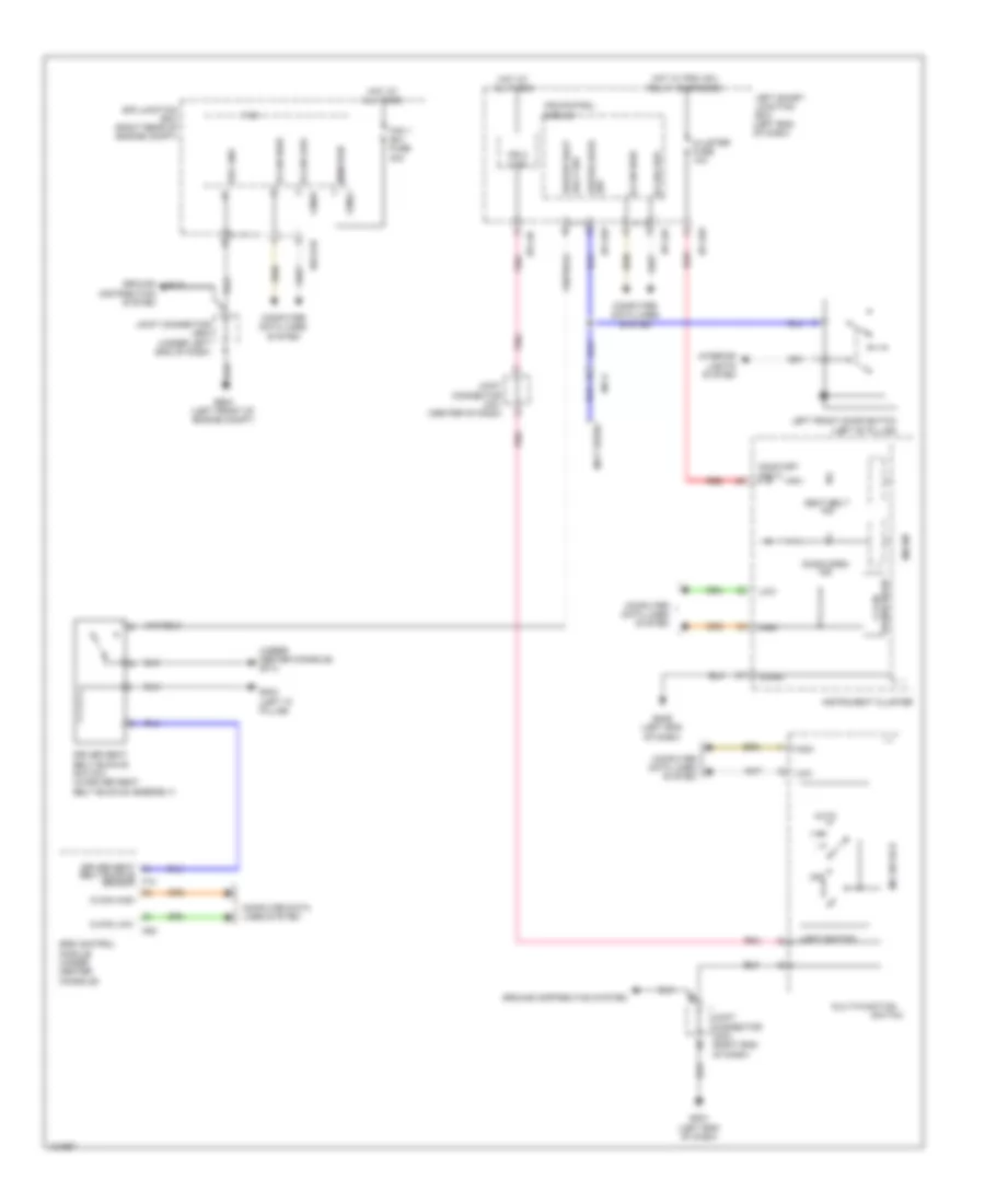 https://portal-diagnostov.com/license.html
Automotive Electricians Portal FZCO
Automotive Electricians Portal FZCO
https://portal-diagnostov.com/license.html
https://portal-diagnostov.com/license.html
Automotive Electricians Portal FZCO
Automotive Electricians Portal FZCOList of elements for Chime Wiring Diagram for Hyundai Equus Ultimate 2014:
- (not used)
- (under center console) gf13
- Auto
- B-can high
- B-can low
- Belt buckle sensor
- C-can high
- C-can low
- Cluster fuse 10a
- Computer data lines system
- Door open ind
- Driver door sw
- Driver seat
- Driver seat belt buckle switch (in driver seat belt buckle assembly)
- Driver seat belt sw
- Drl gnd
- E/r junction box (right rear of engine compt)
- E/r-e1b
- F10
- Fam
- Fam 1 (b+) fuse 40a
- Fam-a
- Fam-b
- Ge03 (left front of engine compt)
- Gf03 (left "c" pillar)
- Gm01 (left end of dash)
- Gm06 (left end of dash)
- Ground distribution system
- High
- Hot at all times
- Hot w/ pdm (ig1) relay energized
- I/p-lhb
- I/p-lhf
- Instrument cluster
- Interior lights system
- Ips 3 (1ch)
- Ips control module
- Joint connector je02 (under left end of dash)
- Joint connector jm01 (center of dash)
- Joint connector jm03 (right end of dash)
- Left front door switch (left "b" pillar)
- Left smart junction box (left end of dash)
- Light switch
- Low
- M/f sw ecu
- M53
- Mem pwr
- Mf11
- Micom
- Multi-function
- Off
- On/start input
- Pnk
- Red
- S-gnd
- Seat belt ind
- Srs control module (under center console)
- Switch
- Transceiver c-can
Tire Pressure Monitoring Wiring Diagram for Hyundai Equus Ultimate 2014
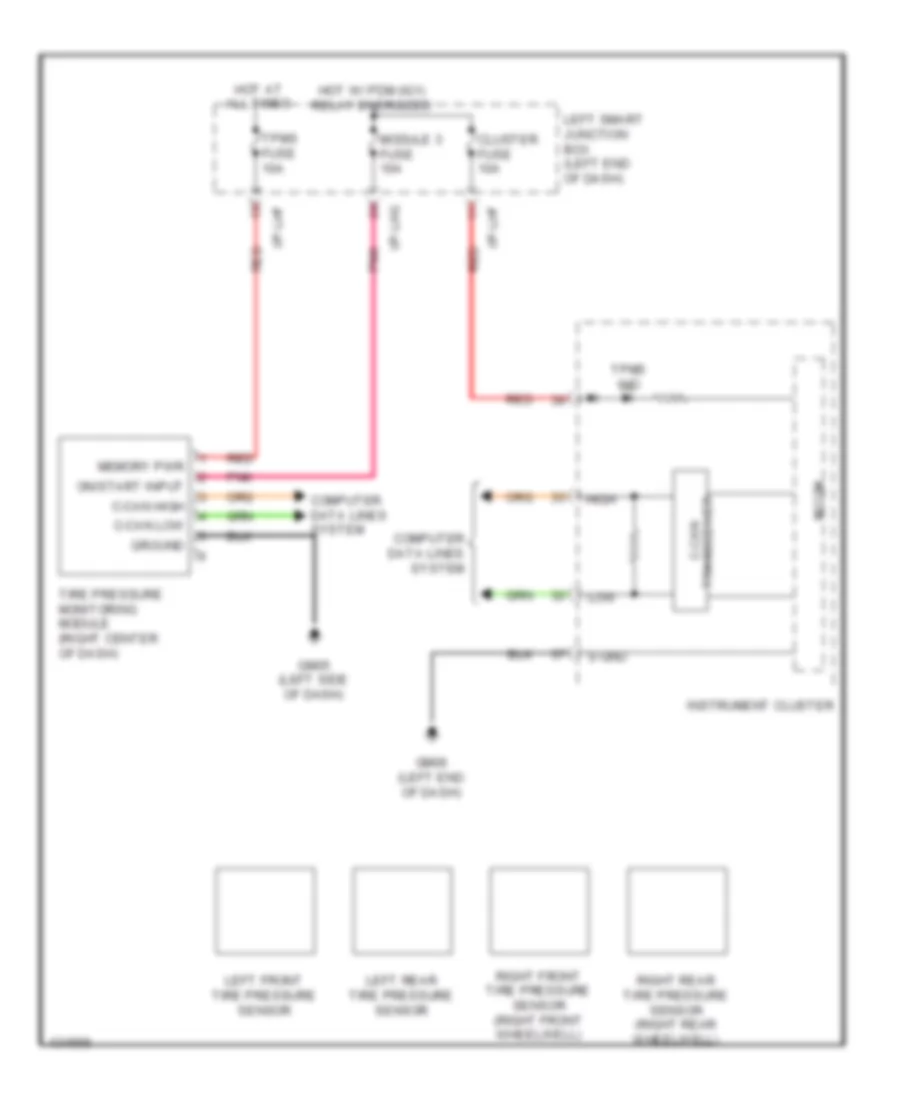 https://portal-diagnostov.com/license.html
Automotive Electricians Portal FZCO
Automotive Electricians Portal FZCO
https://portal-diagnostov.com/license.html
https://portal-diagnostov.com/license.html
Automotive Electricians Portal FZCO
Automotive Electricians Portal FZCOList of elements for Tire Pressure Monitoring Wiring Diagram for Hyundai Equus Ultimate 2014:
- C-can high
- C-can low
- Cluster fuse 10a
- Computer data lines system
- Gm05 (left side of dash)
- Gm06 (left end of dash)
- Ground
- High
- Hot at all times
- Hot w/ pdm (ig1) relay energized
- I/p-lhf
- I/p-lhg
- Instrument cluster
- Left front tire pressure sensor
- Left rear tire pressure sensor
- Left smart junction box (left end of dash)
- Low
- Memory pwr
- Micom
- Module 3 fuse 10a
- On/start input
- Pnk
- Red
- Right front tire pressure sensor (right front wheelwell)
- Right rear tire pressure sensor (right rear wheelwell)
- S-gnd
- Tire pressure monitoring module (right center of dash)
- Tpms fuse 10a
- Tpms ind
- Transceiver c-can
WIPER/WASHER
Wiper/Washer Wiring Diagram for Hyundai Equus Ultimate 2014
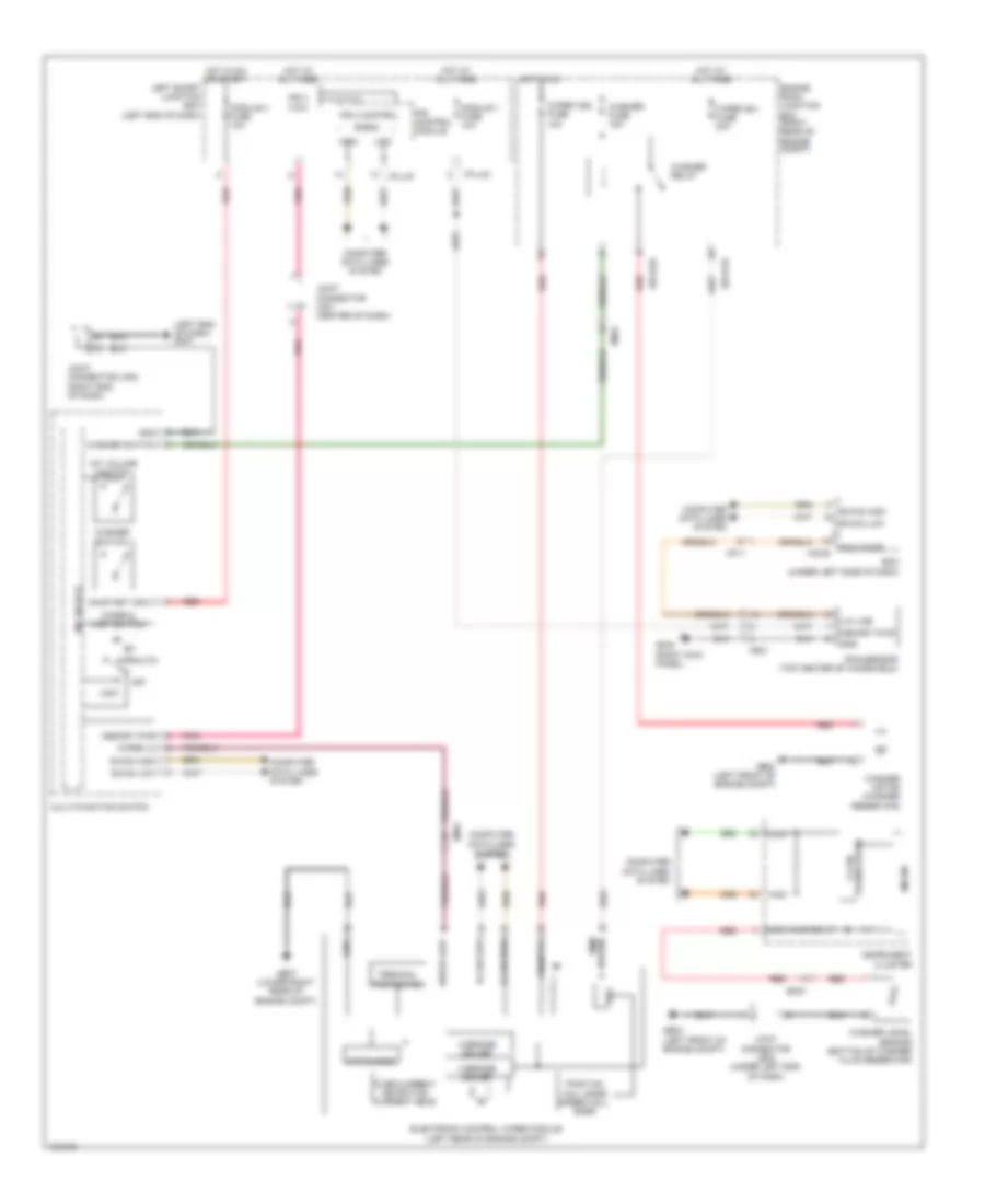 https://portal-diagnostov.com/license.html
Automotive Electricians Portal FZCO
Automotive Electricians Portal FZCO
https://portal-diagnostov.com/license.html
https://portal-diagnostov.com/license.html
Automotive Electricians Portal FZCO
Automotive Electricians Portal FZCOList of elements for Wiper/Washer Wiring Diagram for Hyundai Equus Ultimate 2014:
- (left end of dash) gm01
- B-can
- B-can high
- B-can low
- Bcm (under left side of dash)
- Computer data lines system
- E/r-e1b
- E/r-e2b
- Electronic control wiper module (left rear of engine compt)
- Em21
- Em31
- Engine room junction box (right rear of engine compt)
- Fr21
- Ge03 (left front of engine compt)
- Ge07 (lower right rear of engine compt)
- Gf05 (right kick panel)
- Gnd
- H-bridge driver
- High
- Hot at all times
- Hot in on
- Hot in on or start
- I/p-lhc
- I/p-lhf
- Instrument cluster
- Int (auto)
- Int volume switch
- Ips 3 (1ch)
- Ips 3 control
- Ips control module
- Joint connector je02 (under left end of dash)
- Joint connector jm01 (center of dash)
- Joint connector jm03 (right end of dash)
- Left smart junction box (left end of dash)
- Lin line
- Low
- Low washer i/p
- M/f sw ecu
- M32-b
- Memory pwr
- Mf11
- Micom
- Mist
- Module 1 fuse 10a
- Module 4 fuse 10a
- Multi-function switch
- Off
- On input
- On/start input
- Over current detection current meas
- Pnk
- Position hall snsr speed hall snsr
- Power mem
- Rain sensor (top center of windshield)
- Rain snsr
- Red
- Reg
- Terminal protection
- Transceiver c-can
- Washer fuse 15a
- Washer level sensor (bottom of washer fluid reservoir)
- Washer motor (washer reservoir)
- Washer relay
- Washer switch
- Watch-dog
- Wiper & mist switch
- Wiper (b+) fuse 30a
- Wiper (ig2) fuse 10a
- Wiper lo
- Wiper low

 Čeština
 Dansk
Dansk Deutsch
 Ελληνικά
 English
 English
 Español
 Suomi
Suomi Français
 Français
 עברית
עברית Hrvatski
 Magyar
 Italiano
 日本語
日本語 한국어
한국어 Nederlands
 Polski
 Português
 Português
 Română
 Русский
 Slovenčina
 Slovenščina
 Svenska
 Türkçe
