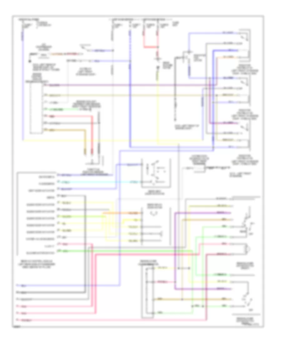
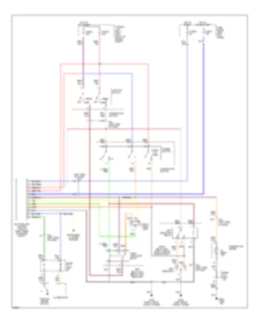
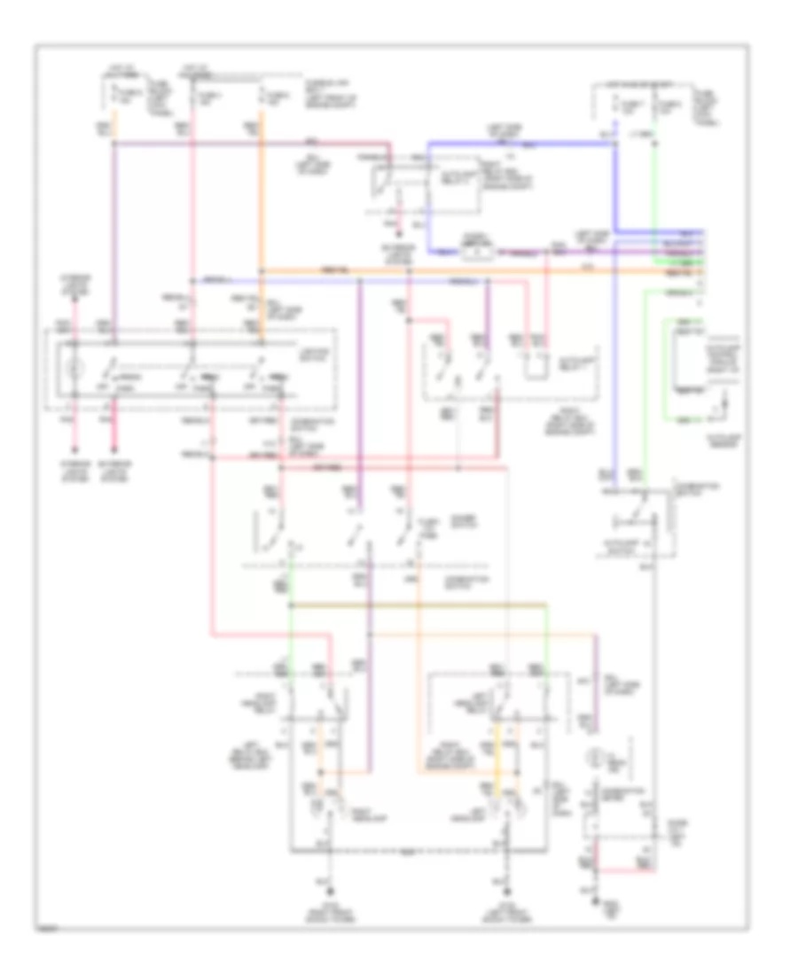
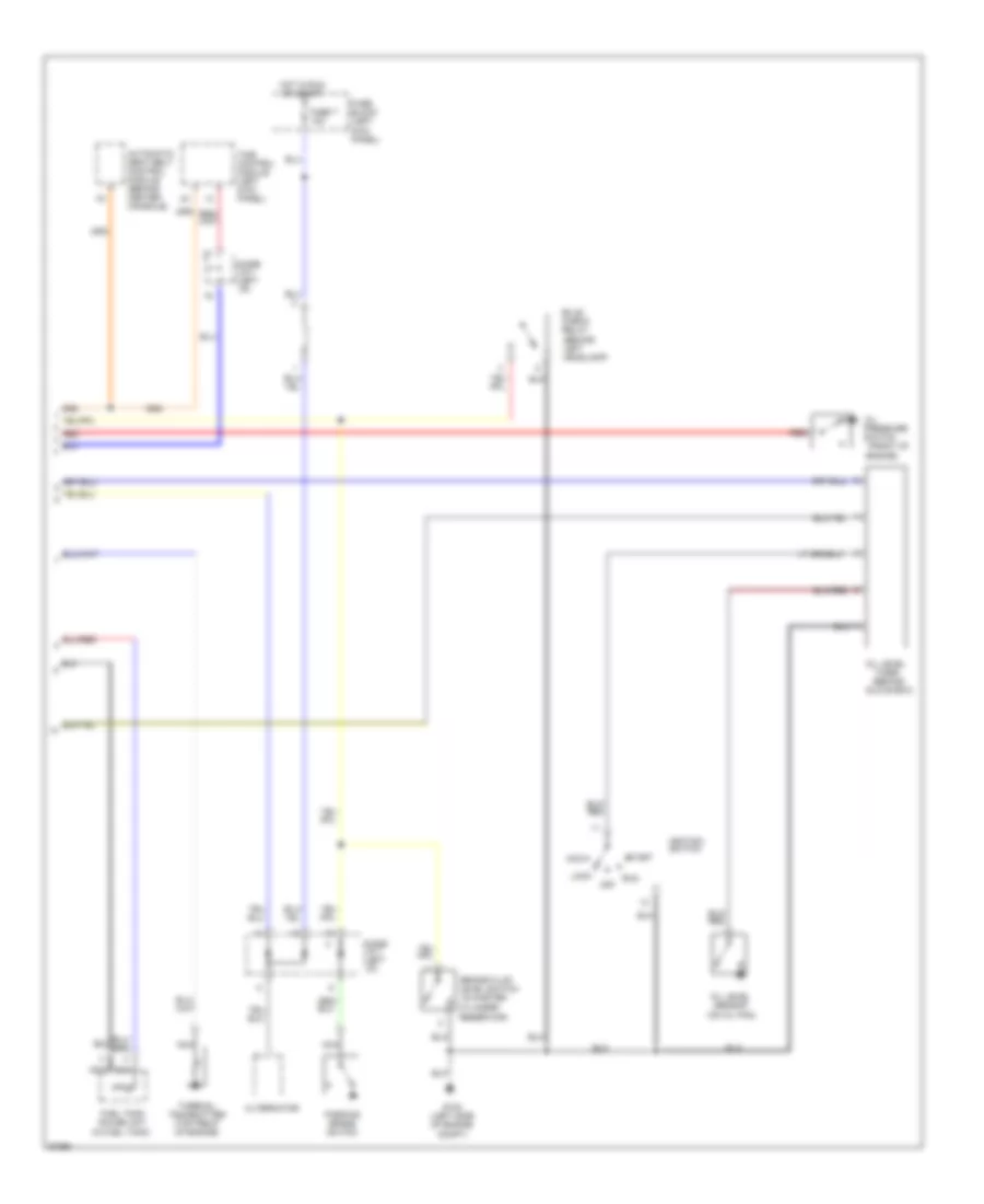
AIR CONDITIONING
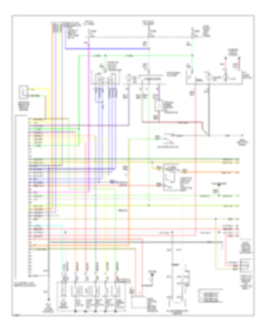
Air Conditioning Wiring Diagrams (1 of 2) for Nissan Quest GXE 1994
 https://portal-diagnostov.com/license.html
Automotive Electricians Portal FZCO
Automotive Electricians Portal FZCO
https://portal-diagnostov.com/license.html
https://portal-diagnostov.com/license.html
Automotive Electricians Portal FZCO
Automotive Electricians Portal FZCO
List of elements for Air Conditioning Wiring Diagrams (1 of 2) for Nissan Quest GXE 1994:
- 1994 vftc c
- A/c control module (center of i/p)
- A/c high pressure switch (right front of engine)
- A/c low pressure switch (right side of engine comp., on accumulator)
- A/c pressure
- A/c request
- Acc
- Battery
- Bi-level/floor in
- Defog
- Engine comp.)
- Engine control module (behind glove box)
- Exterior lights system
- Floor/defog
- Fnt blend door
- Fnt blend door mtr
- Fnt blower mtr relay
- Front air mix door motor (behind right center of i/p, on a/c plenum)
- Front blower motor
- Front blower motor relay (behind left side of i/p)
- Front blower motor resistor (behind right side of i/p, in a/c- heater plenum)
- Front blower motor switch
- Front intake door motor (behind right side of i/p, on a/c-heater plenum)
- Front intake dr cont
- Fuse a 20a
- Fuse b 20a
- Fuse block
- Fuse m 10a
- Fuse u 10a
- G100 (left front of
- G110 (left front
- G201 (right side
- G202 (left side
- Ground
- Hot at all times
- Hot in on or start
- Iac relay- ficd relay (right side of engine comp.)
- Iac valve ficd solenoid valve (front of engine)
- Ignition switch
- Illumination power
- Illumination return
- J/c 1
- Lock
- Med hi
- Med lo
- Mode actuator
- Mode actuator mtr
- Mode actuator signal
- Mode door motor (behind left center of i/p)
- Of engine)
- Of i/p)
- Off
- Pnk
- Position switch
- Power
- Power in
- Run
- Start
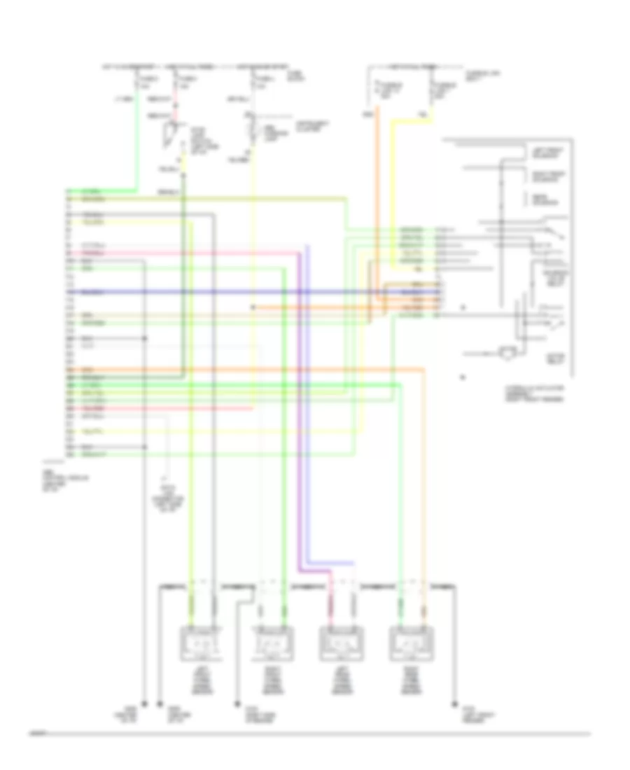
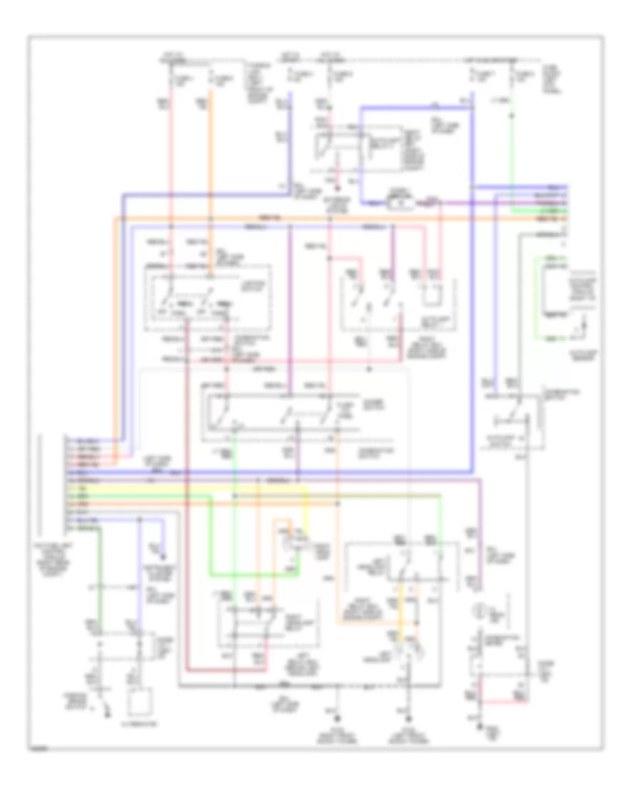
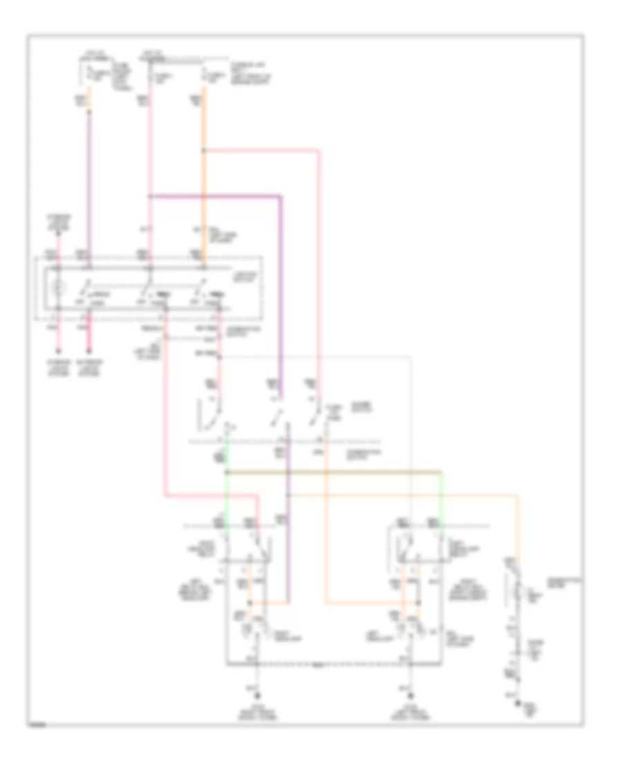
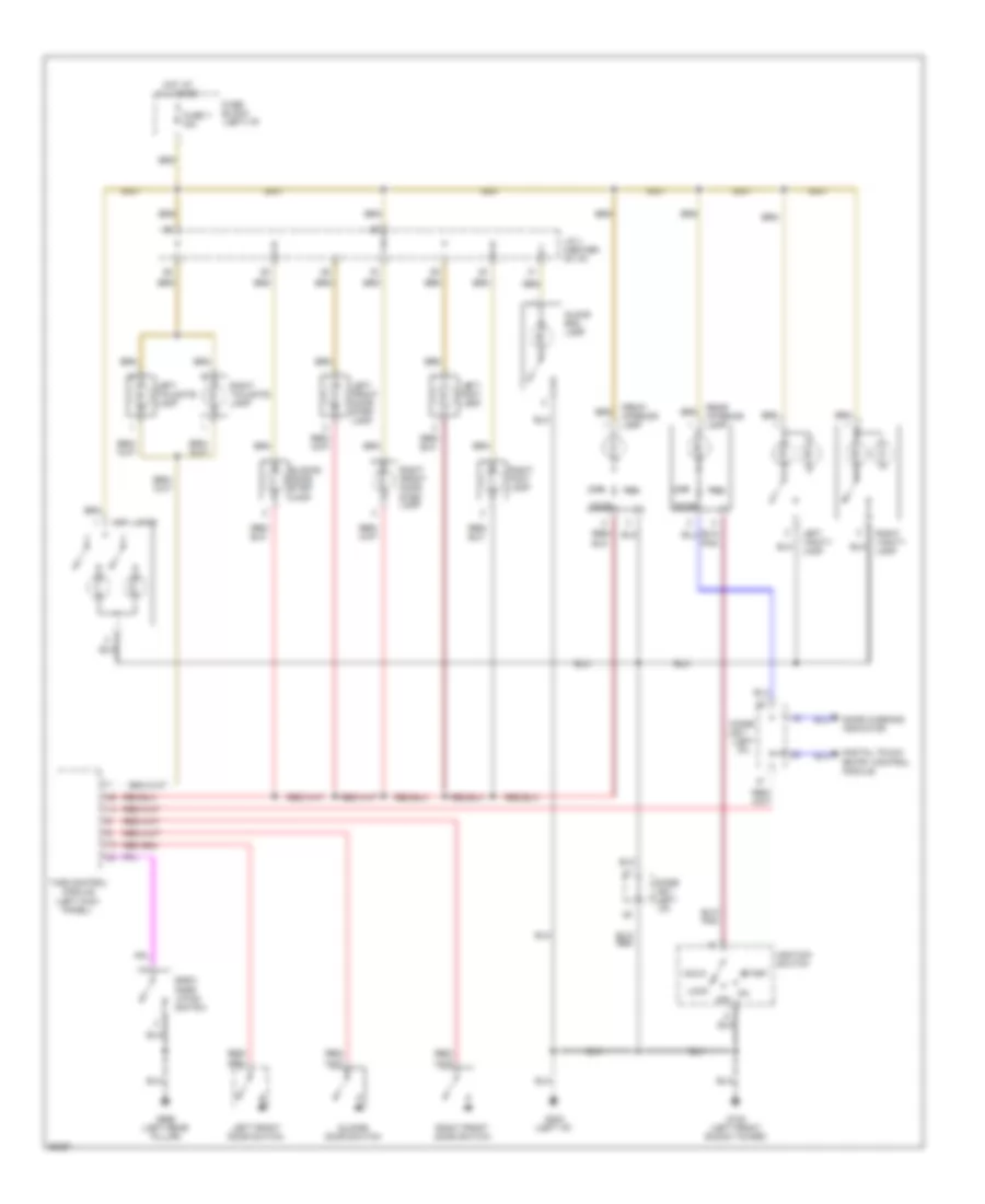
Air Conditioning Wiring Diagrams (2 of 2) for Nissan Quest GXE 1994
 https://portal-diagnostov.com/license.html
Automotive Electricians Portal FZCO
Automotive Electricians Portal FZCO
https://portal-diagnostov.com/license.html
https://portal-diagnostov.com/license.html
Automotive Electricians Portal FZCO
Automotive Electricians Portal FZCOList of elements for Air Conditioning Wiring Diagrams (2 of 2) for Nissan Quest GXE 1994:
- (left front of engine comp.)
- (left front of engine comp., in relay box)
- (left front of engine)
- (left rear side of passenger
- A/c compressor clutch
- A/c relay
- Area, behind "b" pillar)
- Blend door actuator
- Blower motor switch
- Defog
- Engine comp.)
- Engine comp., on side of strut tower)
- Engine control module (behind glove box)
- Engine coolant temperature sensor (right front of engine)
- Floor/defog
- Fuse 7 65a
- Fuse box
- Fuse e 15a
- Fuse t 10a
- Fuse u 10a
- Fusible link box #1
- G100 (left front of
- G104 (left rear of
- G110 (left front
- Hot at all times
- Hot in acc or run
- Hot in on or run
- Ign power in
- Illum lt
- Motor resistor
- Of engine)
- Off
- Pnk
- Radiator fan motor
- Radiator fan relay #1
- Radiator fan relay #2
- Radiator fan relay #3
- Rear
- Rear a/c control module
- Rear air mix door motor
- Rear blower
- Rear blower motor
- Rear blower motor switch (front)
- Rear blower motor switch (rear) 1994 vftc c
- Rear vent door actuator
- Red
- Throttle position sensor
- Vent door actuator
- Water cock solenoid valve (right rear of engine)
- Water valve solenoid
ANTI-LOCK BRAKES
Anti-lock Brake Wiring Diagrams for Nissan Quest GXE 1994
 https://portal-diagnostov.com/license.html
Automotive Electricians Portal FZCO
Automotive Electricians Portal FZCO
https://portal-diagnostov.com/license.html
https://portal-diagnostov.com/license.html
Automotive Electricians Portal FZCO
Automotive Electricians Portal FZCOList of elements for Anti-lock Brake Wiring Diagrams for Nissan Quest GXE 1994:
- 10a
- 15a
- Abs control module (center of i/p)
- Abs warning lamp
- Data link connector (left side of i/p)
- Fuse block
- Fuse u
- Fuse x
- Fuse z
- Fusible link 1 20a
- Fusible link 14 30a
- Fusible link box-1
- G100 (left front fender)
- G120 (right side of engine)
- G206 (center of i/p)
- Hot at all times
- Hot in on or start
- Hydraulic actuator assembly (right front fender)
- Instrument cluster
- Left front solenoid
- Left front wheel speed sensor
- Left rear wheel speed sensor
- Motor
- Motor relay
- Nca
- Rear solenoid
- Right front solenoid
- Right front wheel speed sensor
- Right rear wheel speed sensor
- Solenoid valve relay
- Stop lamp switch (left side of i/p)
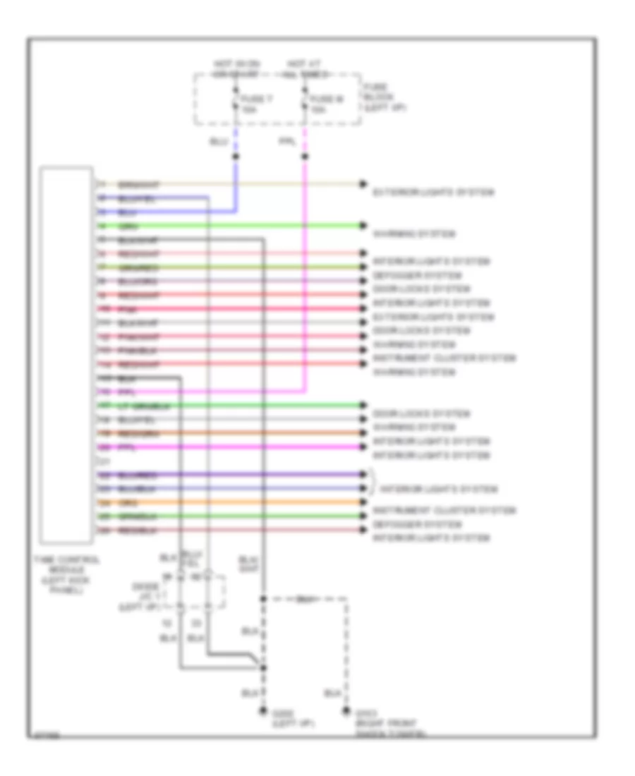
BODY COMPUTER
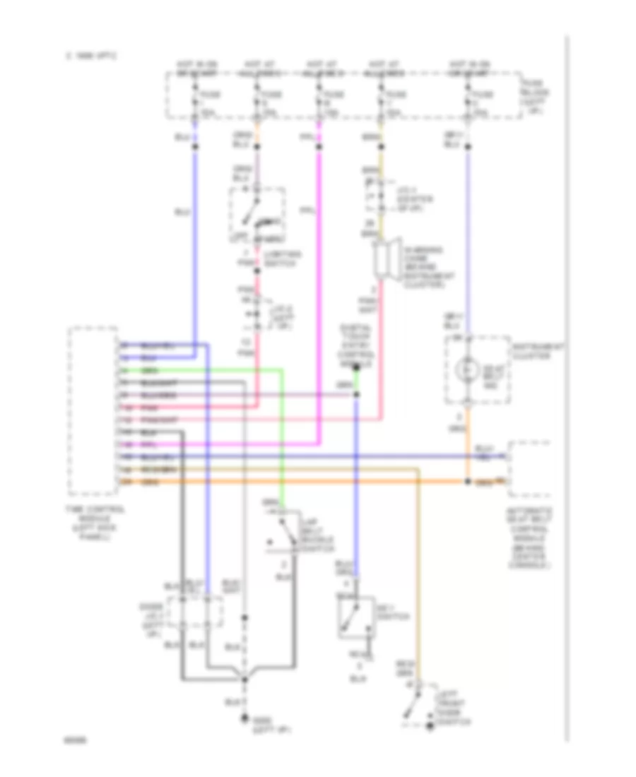
Time Control Module Wiring Diagram for Nissan Quest GXE 1994
 https://portal-diagnostov.com/license.html
Automotive Electricians Portal FZCO
Automotive Electricians Portal FZCO
https://portal-diagnostov.com/license.html
https://portal-diagnostov.com/license.html
Automotive Electricians Portal FZCO
Automotive Electricians Portal FZCOList of elements for Time Control Module Wiring Diagram for Nissan Quest GXE 1994:
- Defogger system
- Diode j/c 1 (left i/p)
- Door locks system
- Exterior lights system
- Fuse block (left i/p)
- Fuse m 10a
- Fuse t 10a
- G103 (right front shock tower)
- G202 (left i/p)
- Hot at all times
- Hot in on or start
- Instrument cluster system
- Interior lights system
- Pnk
- Time control module (left kick panel)
- Warning system
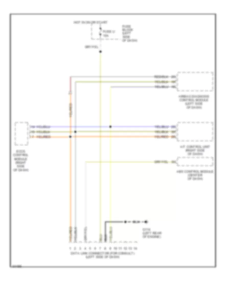
COMPUTER DATA LINES
Computer Data Lines for Nissan Quest GXE 1994
 https://portal-diagnostov.com/license.html
Automotive Electricians Portal FZCO
Automotive Electricians Portal FZCO
https://portal-diagnostov.com/license.html
https://portal-diagnostov.com/license.html
Automotive Electricians Portal FZCO
Automotive Electricians Portal FZCOList of elements for Computer Data Lines for Nissan Quest GXE 1994:
- A/t control unit (right side of dash)
- Abs control module (center of dash)
- Airbag diagnosis control module (left side of dash)
- Data link connector (for consult) (left side of dash)
- Eccs control module (right side of dash)
- Fuse block (left side of dash)
- Fuse u 10a
- G114 (left rear of engine)
- Hot in on or start
Data Link Connector Wiring Diagram for Nissan Quest GXE 1994
 https://portal-diagnostov.com/license.html
Automotive Electricians Portal FZCO
Automotive Electricians Portal FZCO
https://portal-diagnostov.com/license.html
https://portal-diagnostov.com/license.html
Automotive Electricians Portal FZCO
Automotive Electricians Portal FZCOList of elements for Data Link Connector Wiring Diagram for Nissan Quest GXE 1994:
- A/t control unit (right side of dash)
- Abs control module (center of dash)
- Airbag diagnosis control module (left side of dash)
- Data link connector (for consult) (left side of dash)
- Eccs control module (right side of dash)
- Fuse block (left side of dash)
- Fuse u 10a
- G114 (left rear of engine)
- Hot in on or start
COOLING FAN
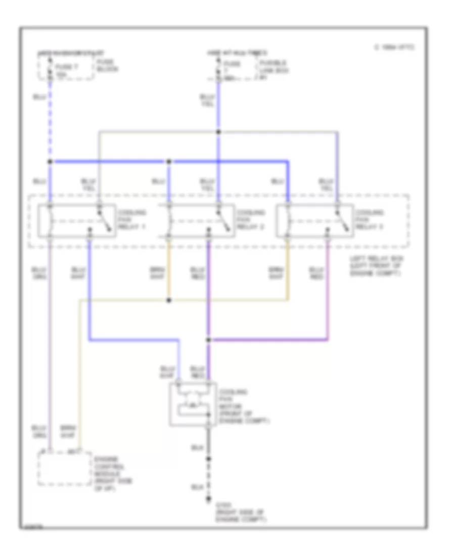
Cooling Fan Wiring Diagram for Nissan Quest GXE 1994
 https://portal-diagnostov.com/license.html
Automotive Electricians Portal FZCO
Automotive Electricians Portal FZCO
https://portal-diagnostov.com/license.html
https://portal-diagnostov.com/license.html
Automotive Electricians Portal FZCO
Automotive Electricians Portal FZCOList of elements for Cooling Fan Wiring Diagram for Nissan Quest GXE 1994:
- 1994 vftc c
- Cooling fan motor (front of engine compt)
- Cooling fan relay 1
- Cooling fan relay 2
- Cooling fan relay 3
- Engine control module (right side of i/p)
- Fuse 65a
- Fuse block
- Fuse t 10a
- Fusible link box #1
- G103 (right side of engine compt)
- Hot at all times
- Hot in on or start
- Left relay box (left front of engine compt)
CRUISE CONTROL
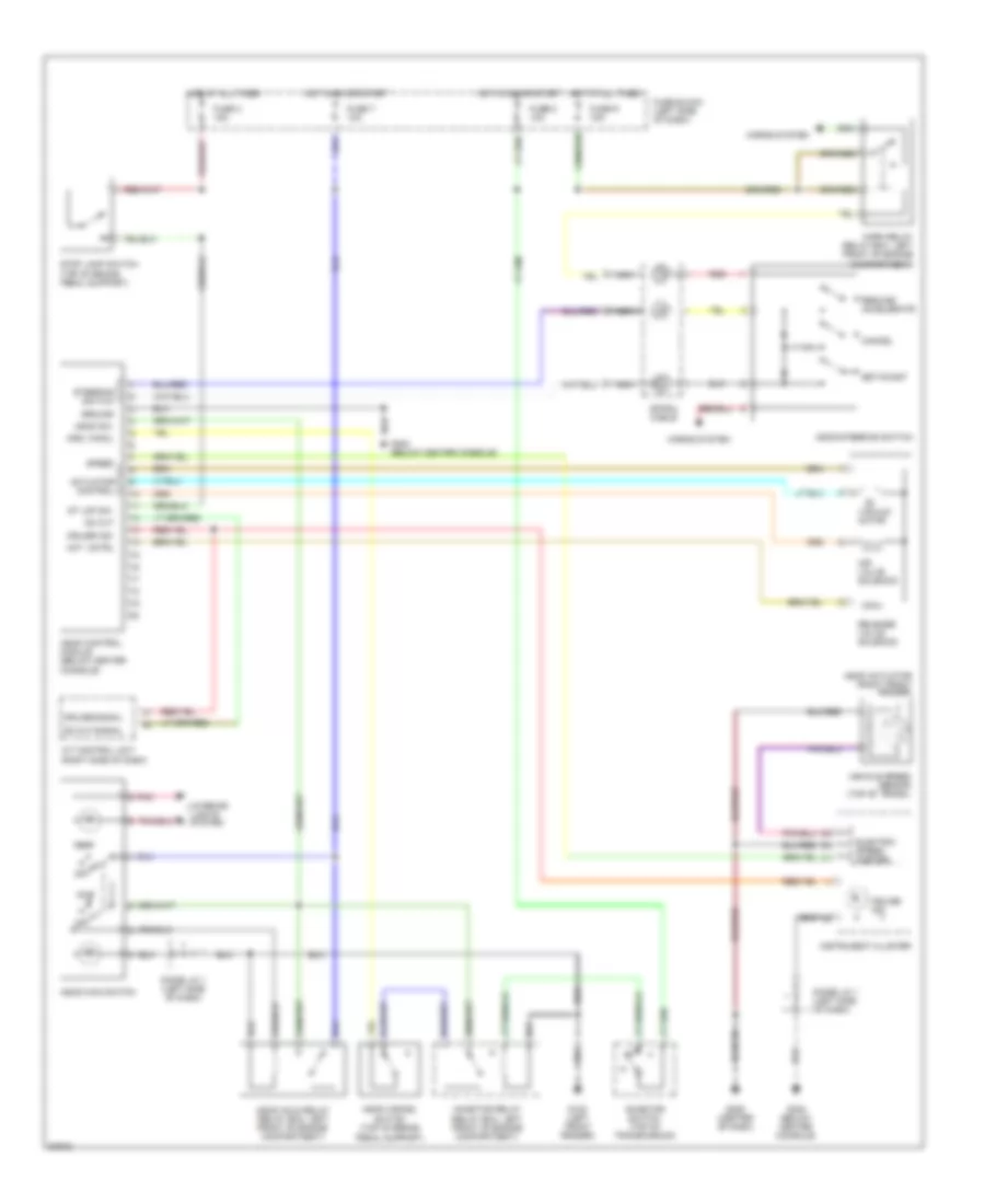
Cruise Control Wiring Diagram for Nissan Quest GXE 1994
 https://portal-diagnostov.com/license.html
Automotive Electricians Portal FZCO
Automotive Electricians Portal FZCO
https://portal-diagnostov.com/license.html
https://portal-diagnostov.com/license.html
Automotive Electricians Portal FZCO
Automotive Electricians Portal FZCOList of elements for Cruise Control Wiring Diagram for Nissan Quest GXE 1994:
- A/t control unit (right side of dash)
- Act. cntrl
- Actuator control
- Air valve solenoid
- Ascd actuator (right front fender)
- Ascd cancel switch (top of brake
- Ascd control module (below center
- Ascd hold relay (relay box, left front of engine compartment)
- Ascd main switch
- Ascd steering switch
- Ascd sw.
- Cancel
- Console)
- Crs. cancl
- Cruise ind.
- Cruise signal
- Diode j/c 1 (left side of dash)
- Electric speed- ometer
- Fuse block (left side of dash)
- Fuse r 15a
- Fuse t 10a
- Fuse x 15a
- Fuse z 10a
- G100 (left front fender)
- G206 (center of dash)
- G302 (below center console)
- Ground
- Horn relay (relay box, left front of engine compartment)
- Horns system
- Hot at all times
- Hot at all times hot in on or start
- Hot in on or start
- Inhibitor relay (relay box, left front of engine compartment)
- Inhibitor switch (top of transmission)
- Instrument cluster
- Interior lights system
- Nca
- Od cut
- Od cut signal
- Off
- Pedal support)
- Pnk
- Red
- Release valve solenoid
- Resume/ accelerate
- Set/coast
- Speed
- Spiral cable
- St lmp sw.
- Steering switch
- Stop lamp switch (top of brake pedal support)
- Vacuum motor
- Vehicle speed sensor (top of trans.)
DEFOGGERS
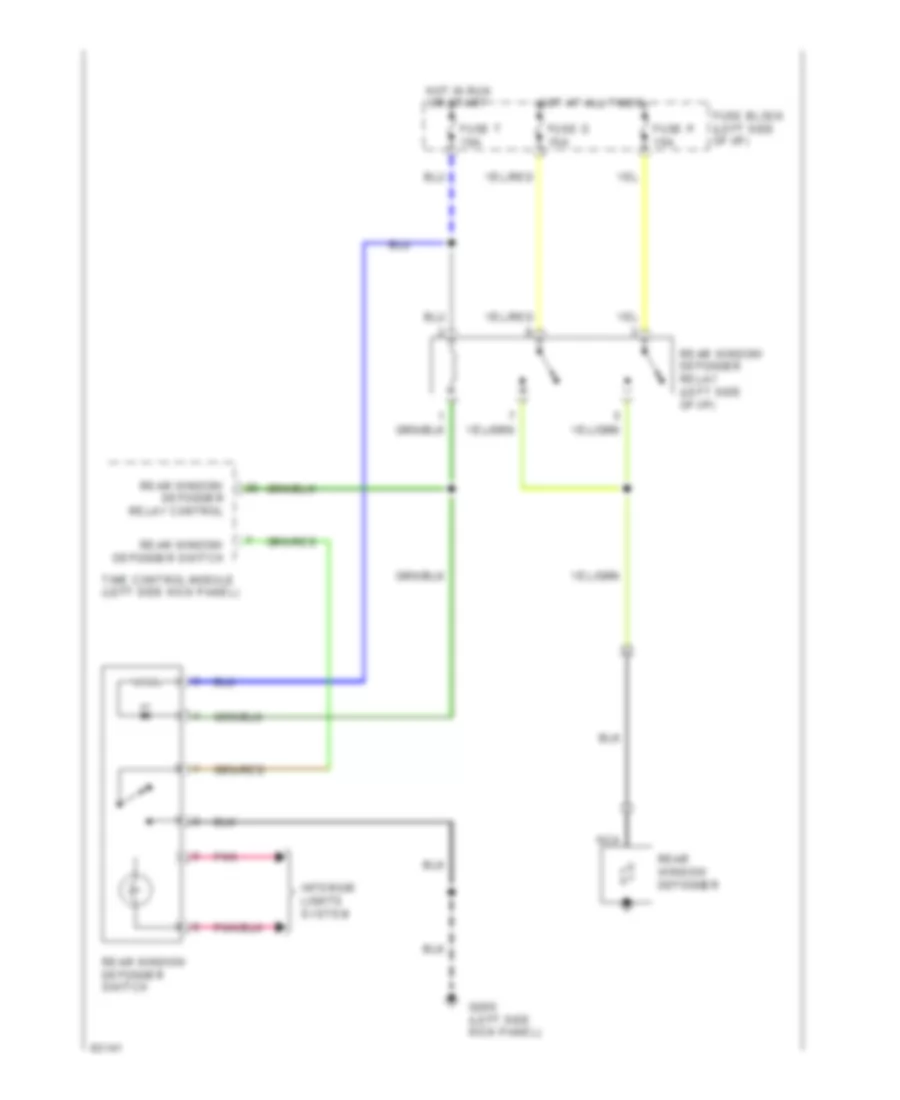
Defogger Wiring Diagram for Nissan Quest GXE 1994
 https://portal-diagnostov.com/license.html
Automotive Electricians Portal FZCO
Automotive Electricians Portal FZCO
https://portal-diagnostov.com/license.html
https://portal-diagnostov.com/license.html
Automotive Electricians Portal FZCO
Automotive Electricians Portal FZCOList of elements for Defogger Wiring Diagram for Nissan Quest GXE 1994:
- Fuse block (left side of i/p)
- Fuse o 10a
- Fuse p 10a
- Fuse t 10a
- G200 (left side kick panel)
- Hot at all times
- Hot in run or start
- Interior lights system
- Nca
- Pnk
- Rear window defogger
- Rear window defogger relay (left side of i/p)
- Rear window defogger relay control
- Rear window defogger switch
- Time control module (left side kick panel)
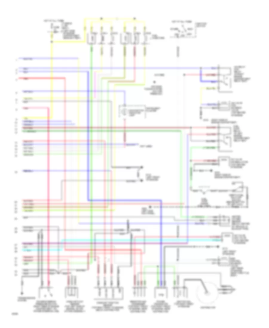
ENGINE PERFORMANCE
3.0L
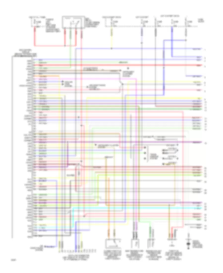
3.0L, Engine Performance Wiring Diagrams (1 of 2) for Nissan Quest GXE 1994
 https://portal-diagnostov.com/license.html
Automotive Electricians Portal FZCO
Automotive Electricians Portal FZCO
https://portal-diagnostov.com/license.html
https://portal-diagnostov.com/license.html
Automotive Electricians Portal FZCO
Automotive Electricians Portal FZCOList of elements for 3.0L, Engine Performance Wiring Diagrams (1 of 2) for Nissan Quest GXE 1994:
- mil
- (left side of i/p, on bottom
- (w/ electronic cluster only)
- 10a
- 15a
- 25a
- Acr
- Air conditioning system
- Air conditioning system (a/c relay)
- Ckp
- Ckpref
- Closed throttle postition switch (top left rear of engine on throttle body)
- Cooling fans system
- Data link connector
- Dlc
- Dtc
- Ecm control module (behind top right side of i/p, behind glow box)
- Ecm relay (in left engine compartment fuse panel)
- Ect
- Egr temperature sensor (on underside of throttle body, air intake)
- Egrc
- Egrt
- Engine coolant temperature sensor (top right rear
- Engine, on throttle body)
- Ffs
- Fpr
- Fuse
- Fuse block
- Fuse e
- Fuse g
- Fuse h
- Fuse t
- Fuse u
- Fusible link box-1 (left side of engine compartment near battery)
- Gnd
- Hfan1/hfan2
- Ho2s
- Hot at all times
- Hot in start
- Hot in start or on
- Hps
- Iac
- Idl+
- Idl-
- Ignc
- Ing
- Ings
- Inj1
- Inj2
- Inj3
- Inj4
- Inj5
- Inj6
- Instrument cluster system
- Instrument clusters system
- Kapwr
- Knock sensor (left side of engine)
- Lfan
- Maf+
- Maf-
- Nca
- Of engine)
- Of i/p fuse/relay panel)
- Pcmr
- Pnk
- Pnps
- Psp
- Red
- Rpm
- Sigrtn
- Tcm (tp)
- Throttle position sensor (top left rear of
- Trans- missions system
- Vpwr
- Vref
- Vss
- Vst
3.0L, Engine Performance Wiring Diagrams (2 of 2) for Nissan Quest GXE 1994
 https://portal-diagnostov.com/license.html
Automotive Electricians Portal FZCO
Automotive Electricians Portal FZCO
https://portal-diagnostov.com/license.html
https://portal-diagnostov.com/license.html
Automotive Electricians Portal FZCO
Automotive Electricians Portal FZCOList of elements for 3.0L, Engine Performance Wiring Diagrams (2 of 2) for Nissan Quest GXE 1994:
- (inside fuel tank)
- (left front of engine)
- (left side kick panel)
- (left side of engine compartment near battery)
- (not used)
- (right side of engine compartment)
- (top center of engine)
- Acc
- Air condi- tioning system (a/c high press sw)
- Camshaft position sensor (top right front of engine, below distributor)
- Ckp out
- Ckp ref
- Distributor
- Egr control solenoid valve (left rear of engine, near throttle body)
- Fuel injectors
- Fuel pump
- Fuel pump relay (in left engine compartment relay box)
- Fuse 25a
- Fusible link box-1
- G103
- G103 (right side of engine compartment)
- G110
- G110 (left front of engine)
- G200
- Gnd
- Heated oxygen sensor (below center of vehicle, in exhaust pipe)
- Hot at all times
- Iac relay ficd relay (in right engine compartment relay box)
- Iac valve aac valve
- Iac valve air regulator
- Iac valve ficd solenoid valve (top center of engine)
- Ignitiion switch
- Ignition coil (top right front of engine)
- Inertia fuel shut-off switch (behind bottom of left cowl panel)
- Instrument cluster
- Lock
- Malfunction indicator lamp
- Mass air flow sensor (top left side of engine, on air intake assembly)
- Nca
- Off
- Pnk
- Power steering pressure switch (right rear of engine compartment, on power steering line)
- Power transistor (top right front of engine, near distributor)
- Pwr in
- Red
- Resistor and condenser (top right front of engine, near distributor)
- Start
- Transmissions system
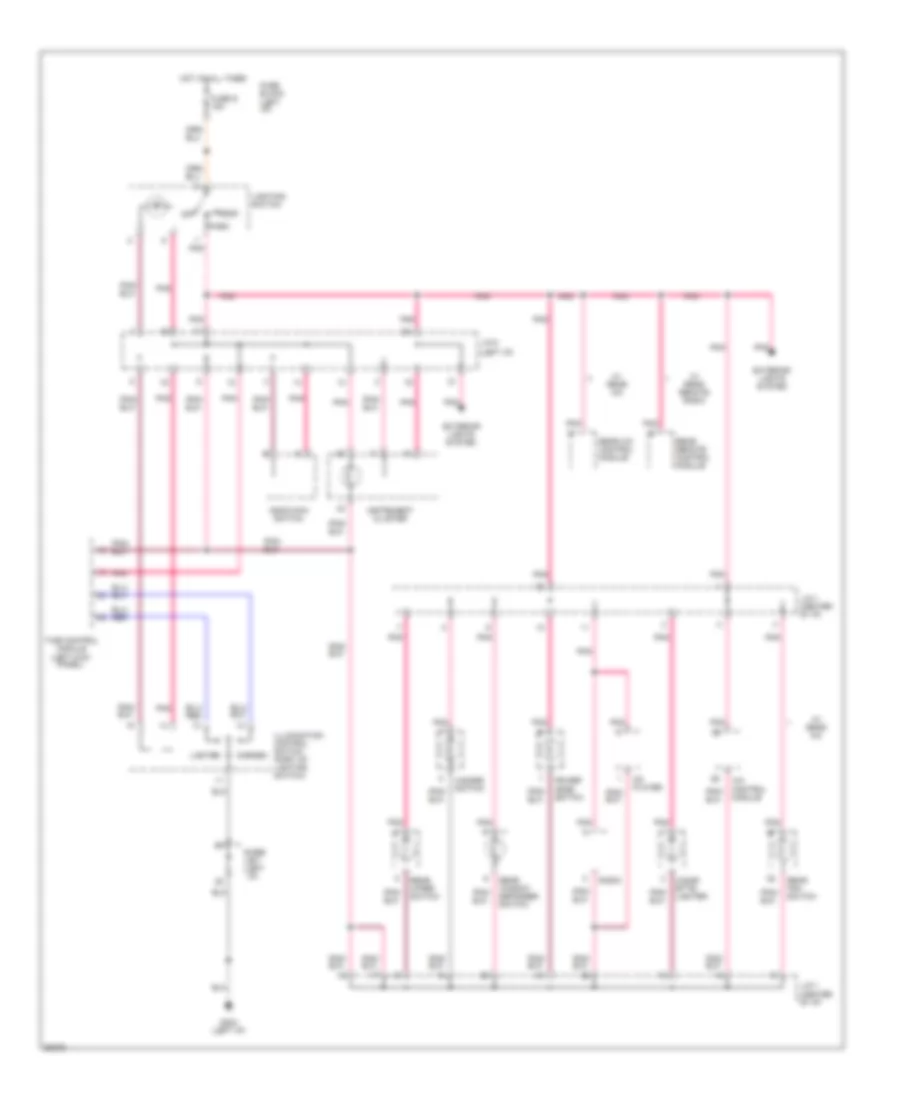
EXTERIOR LIGHTS
Backup & Turn Lamps Wiring Diagram for Nissan Quest GXE 1994
 https://portal-diagnostov.com/license.html
Automotive Electricians Portal FZCO
Automotive Electricians Portal FZCO
https://portal-diagnostov.com/license.html
https://portal-diagnostov.com/license.html
Automotive Electricians Portal FZCO
Automotive Electricians Portal FZCOList of elements for Backup & Turn Lamps Wiring Diagram for Nissan Quest GXE 1994:
- (left front fender)
- (left side "d" pillar)
- (left side of i/p)
- (right front fender)
- Combination flasher unit (left side of i/p)
- Diode j/c 1 (left side of i/p)
- Fuse block (left side of i/p)
- Fuse q 15a
- Fuse v 10a
- Fuse z 10a
- G100
- G101
- G202
- G203 (right side of i/p)
- G999
- Hazard
- Hazard switch
- Hot at all times
- Hot in run or start
- Ill.
- Inhibitor switch (on trans)
- Instrument cluster
- Interior lights system
- Left back-up light
- Left front turn signal light
- Left rear tail/ stop/ turn lights
- Left turn ind.
- Pnk
- Right back-up light
- Right front turn signal light
- Right rear tail/ stop/ turn lights
- Right turn ind.
- Trailer tow connector (behind left side of rear bumper)
- Trailer tow module connector (left rear quarter panel)
- Turn signal & cornering switch
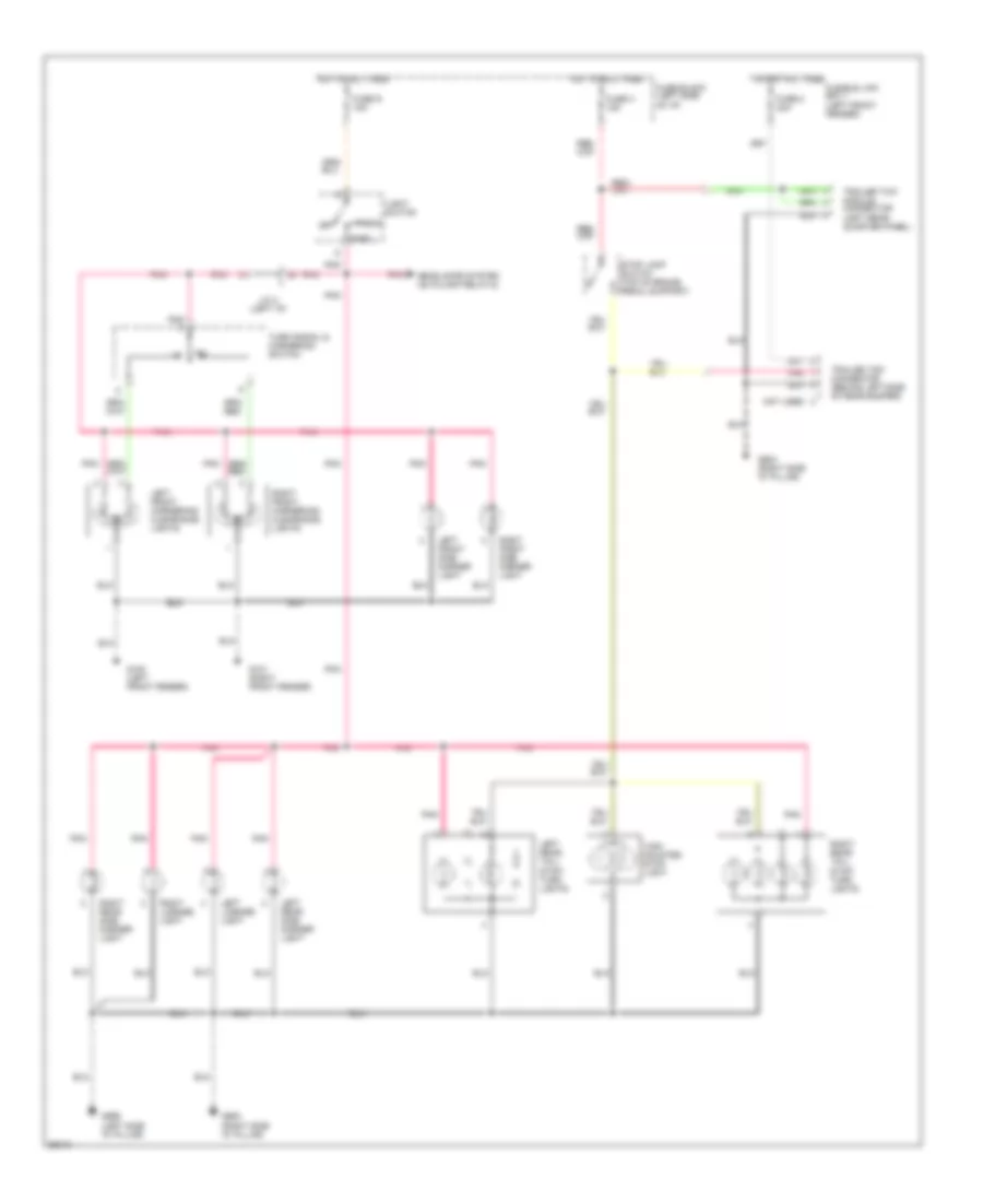
Park, Stop, Tail, & Cornering Lamp Wiring Diagram for Nissan Quest GXE 1994
 https://portal-diagnostov.com/license.html
Automotive Electricians Portal FZCO
Automotive Electricians Portal FZCO
https://portal-diagnostov.com/license.html
https://portal-diagnostov.com/license.html
Automotive Electricians Portal FZCO
Automotive Electricians Portal FZCOList of elements for Park, Stop, Tail, & Cornering Lamp Wiring Diagram for Nissan Quest GXE 1994:
- (left side "d" pillar)
- (right side "d" pillar)
- Fuse 2 20a
- Fuse block (left side of i/p)
- Fuse s 15a
- Fuse x 15a
- Fusible link box 1 (left front fender)
- G100 (left front fender)
- G101 (right front fender)
- G904 (right side "d" pillar)
- G905
- G999
- Head
- Headlamps system (autolamp relay-2)
- High
- Hot at all times
- J/c 2 (left i/p)
- Left front cornering/ clearance lights
- Left front side marker light
- Left license light
- Left rear side marker light
- Left rear tail/ stop/ turn lights
- Light switch
- Mounted
- Not used
- Off
- Park
- Pnk
- Right front cornering/ clearance lights
- Right front side marker light
- Right license light
- Right rear side marker light
- Right rear tail/ stop/ turn lights
- Stop lamp switch (top of brake pedal support)
- Stop light
- Trailer tow connector (behind left side of rear bumper)
- Trailer tow module connector (left rear quarter panel)
- Turn signal & cornering switch
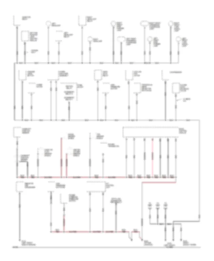
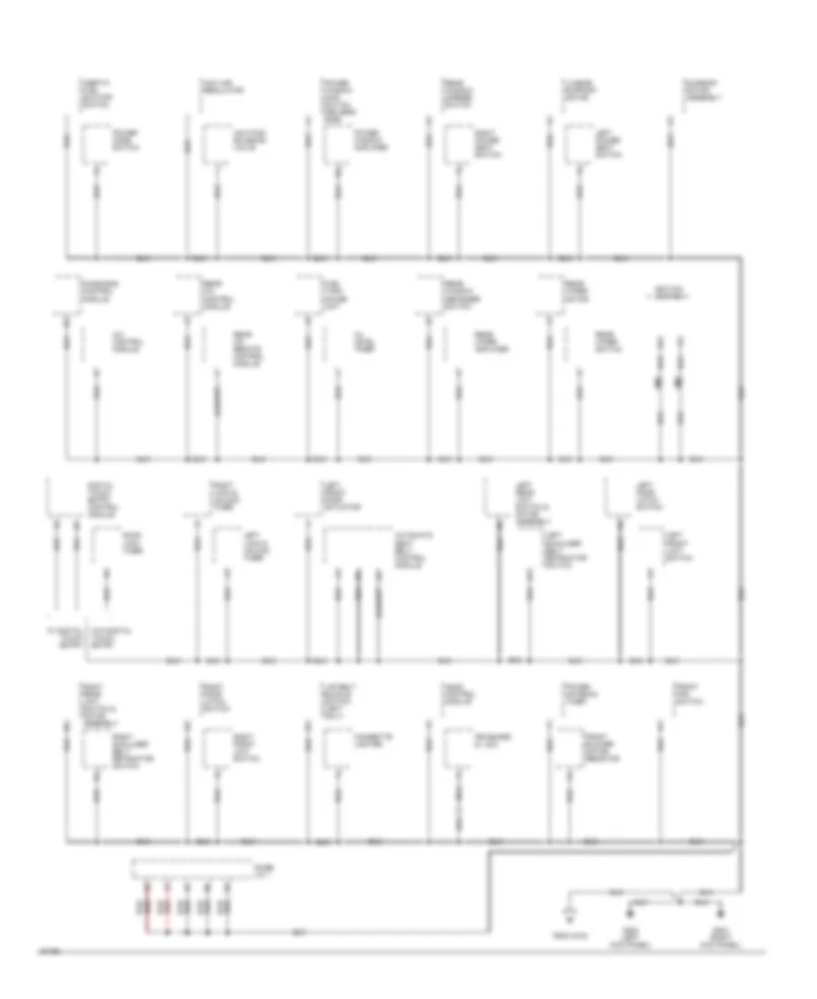
GROUND DISTRIBUTION
Ground Distribution Wiring Diagram (1 of 3) for Nissan Quest GXE 1994
 https://portal-diagnostov.com/license.html
Automotive Electricians Portal FZCO
Automotive Electricians Portal FZCO
https://portal-diagnostov.com/license.html
https://portal-diagnostov.com/license.html
Automotive Electricians Portal FZCO
Automotive Electricians Portal FZCOList of elements for Ground Distribution Wiring Diagram (1 of 3) for Nissan Quest GXE 1994:
- A/t control unit
- Accessory relay-1
- Accessory relay-2
- Ascd hold relay
- Camshaft position sensor
- Camshaft position sensor shield
- Canada only
- Compressor
- Cooling fan motor
- Data link connector for consult
- Daytime running lamp control module
- Eccs control module
- Fuse block
- G102 (left shock tower)
- G103 (right shock tower)
- G110 (left front side of engine)
- G131 g131 (intake manifold)
- Heated oxygen sensor shield
- High pressure switch
- High pressure switch #2
- Ignition relay
- Inhibitor relay
- Knock sensor shield
- Left front cornering/ clearance lamp
- Left front side marker lamp
- Left front turn signal lamp
- Left headlamp
- Left headlamp relay
- Mass air flow sensor shield
- Nca
- Power steering pressure switch
- Power transistor
- Resistor and condenser
- Right front cornering/ clearance lamp
- Right front side marker lamp
- Right front turn signal lamp
- Right headlamp
- Right headlamp relay
- To g200
- To g404
- To g405
- Tps sensor shield
- Transaxle gear selector switch-od
- W/ rear a/c
- Washer level switch
- Water cock solenoid valve
- Wiper amplifier assembly
- Wiper motor
Ground Distribution Wiring Diagram (2 of 3) for Nissan Quest GXE 1994
 https://portal-diagnostov.com/license.html
Automotive Electricians Portal FZCO
Automotive Electricians Portal FZCO
https://portal-diagnostov.com/license.html
https://portal-diagnostov.com/license.html
Automotive Electricians Portal FZCO
Automotive Electricians Portal FZCOList of elements for Ground Distribution Wiring Diagram (2 of 3) for Nissan Quest GXE 1994:
- A/c control module
- Ascd control module
- Automatic seat belt control module
- Cigarette lighter
- Diagnosis control module
- Digital touch entry control module
- Diode j/c 1
- Door lock timer
- From g102
- Front blower motor resistor
- Front fan switch
- Fuel tank gauge unit
- G200 (left kick panel)
- G203 (right kick panel)
- Iacv-air regulator
- Iacv-ficd solenoid valve
- Ignition switch
- Inertia fuel shutoff switch
- Keyboard & l.e.d.
- Lap belt buckle switch (left only)
- Left door latch switch
- Left front door actuator
- Left front limit switch
- Left lock & unlock timer
- Left power seat switch
- Left rear limit switch & motor assembly
- Left shoulder belt retractor switch
- Lumbar support motor
- Nca
- Oil level timer
- Power antenna timer
- Power mode switch
- Power window amplifier
- Power window main switch (driver's side)
- Rear a/c control module
- Rear a/c remote control module
- Rear window defogger switch
- Rear window opener switch
- Rear wiper amplifier
- Rear wiper motor
- Rear wiper switch
- Right door latch switch
- Right front limit switch
- Right lock & unlock timer
- Right power seat switch
- Right rear limit switch & motor assembly
- Right shoulder belt retractor switch
- Smj
- Sunroof motor assembly
- W/ digital touch entry
- W/o digital touch entry
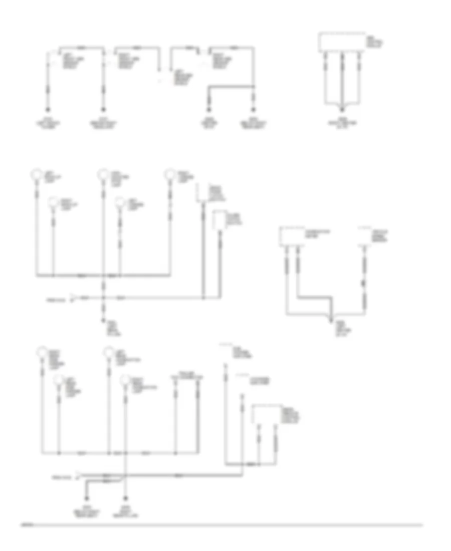
Ground Distribution Wiring Diagram (3 of 3) for Nissan Quest GXE 1994
 https://portal-diagnostov.com/license.html
Automotive Electricians Portal FZCO
Automotive Electricians Portal FZCO
https://portal-diagnostov.com/license.html
https://portal-diagnostov.com/license.html
Automotive Electricians Portal FZCO
Automotive Electricians Portal FZCOList of elements for Ground Distribution Wiring Diagram (3 of 3) for Nissan Quest GXE 1994:
- 4-channel amplifier
- Abs control module
- Back door latch switch
- Combination meter
- From g102
- G102 (left shock tower)
- G107 (behind right headlamp)
- G206 (center ofi/p)
- G206 (left center of i/p)
- G206 (right center of i/p)
- G303 (below right rear seat)
- G404 (left rear pillar)
- G405 (right rear pillar)
- G800 (below right rear seat)
- Glass hatch switch
- High- mounted stop lamp
- Left front abs sensor shield
- Left back-up lamp
- Left license lamp
- Left rear abs sensor shield
- Left rear combination lamp
- Left rear side marker lamp
- Nca
- Rear remote control module
- Right back-up lamp
- Right front abs sensor shield
- Right license lamp
- Right rear abs sensor shield
- Right rear combination lamp
- Right rear side marker lamp
- Smj
- Sub woofer amplifier
- Trailer tow connector
- Vehicle speed sensor
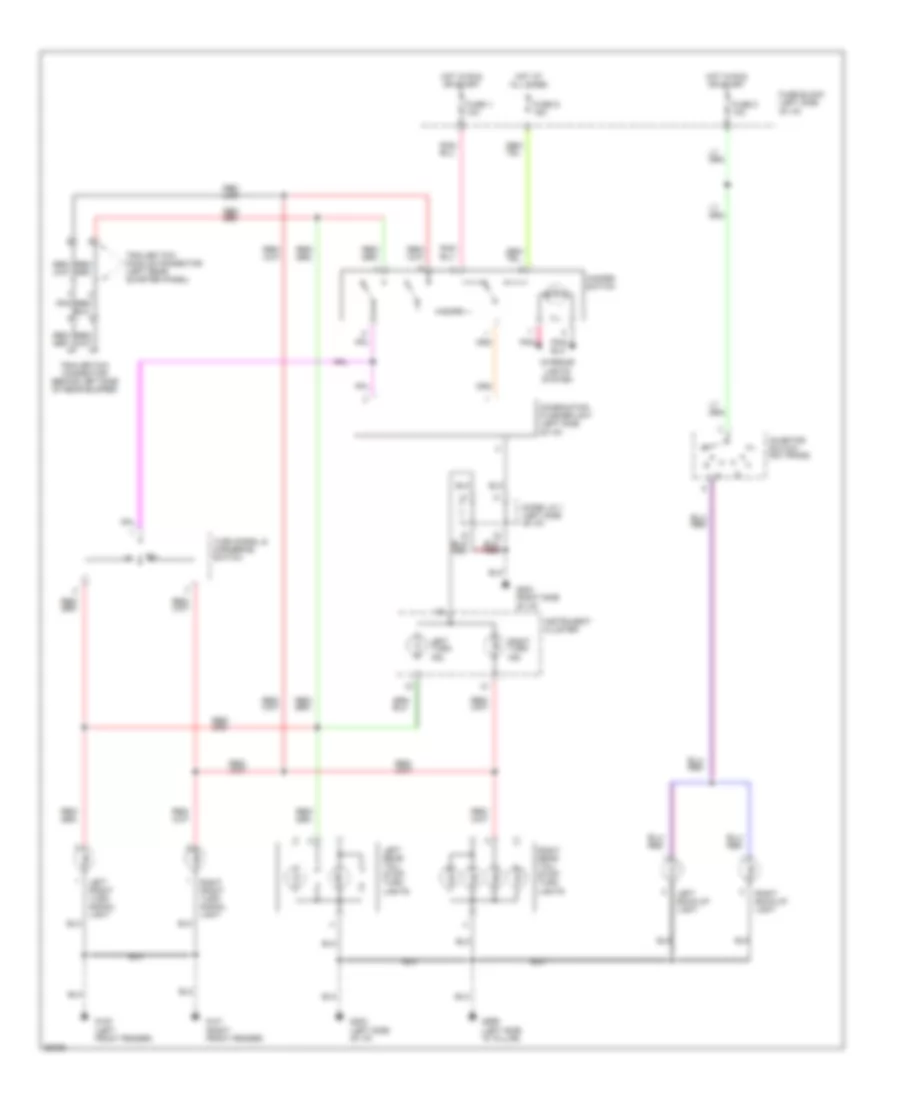
HEADLIGHTS
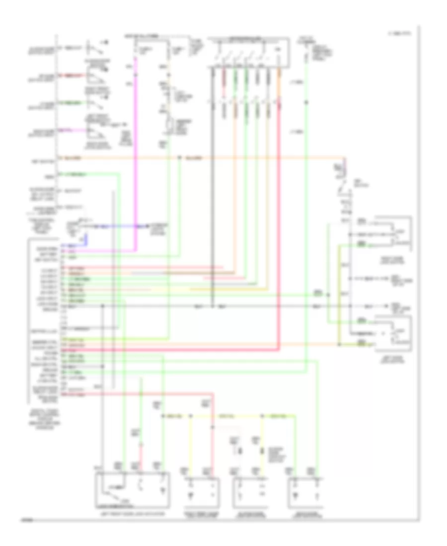
Headlight Wiring Diagram, with DRL, without Autolamps for Nissan Quest GXE 1994
 https://portal-diagnostov.com/license.html
Automotive Electricians Portal FZCO
Automotive Electricians Portal FZCO
https://portal-diagnostov.com/license.html
https://portal-diagnostov.com/license.html
Automotive Electricians Portal FZCO
Automotive Electricians Portal FZCOList of elements for Headlight Wiring Diagram, with DRL, without Autolamps for Nissan Quest GXE 1994:
- (left side of dash) smj
- Alternator
- B10
- Combination meter
- Combination switch
- Daytime light control module (right rear of engine compt)
- Dimmer switch
- Diode j/c 1 (left i/p)
- Flash -to- pass
- Fuse 4 15a
- Fuse 5 15a
- Fuse block (left kick panel)
- Fuse c 5a
- Fuse t 10a
- Fusible link box 1 (left front of engine compt)
- G1o2 (left front shock tower)
- G1o3 (right front shock tower)
- G202 (left i/p)
- H12
- Head
- Headlamp
- Hi beam ind.
- Hot at all times
- Hot in on or start
- Hot in start
- I10
- I12
- Instrument cluster system
- Left
- Left headlamp relay
- Left relay box (behind left headlamp)
- Lighting switch
- Off
- Park
- Parking brake switch
- Red
- Relay
- Right
- Right head- lamp
- Right relay box (right side of engine compt)
- Smj (left side of dash)
Headlight Wiring Diagram, withDRL, with Autolamps for Nissan Quest GXE 1994
 https://portal-diagnostov.com/license.html
Automotive Electricians Portal FZCO
Automotive Electricians Portal FZCO
https://portal-diagnostov.com/license.html
https://portal-diagnostov.com/license.html
Automotive Electricians Portal FZCO
Automotive Electricians Portal FZCOList of elements for Headlight Wiring Diagram, withDRL, with Autolamps for Nissan Quest GXE 1994:
- (left side of dash) smj
- Alternator
- Autolamp control module (right i/p)
- Autolamp relay 1
- Autolamp relay 2
- Autolamp sensor
- Autolamp switch
- B10
- Combination meter
- Combination switch
- Combination switch smj (left side of dash)
- Daytime light control module (right rear of engine compt)
- Dimmer switch
- Diode 1 (left i/p)
- Diode j/c 1 (left i/p)
- Exterior lights system
- Flash -to- pass
- Fuse 4 15a
- Fuse 5 15a
- Fuse block (left kick panel)
- Fuse c 5a
- Fuse s 15a
- Fuse t 10a
- Fuse z 10a
- Fusible link box 1 (left front of engine compt)
- G1o2 (left front shock tower)
- G1o3 (right front shock tower)
- G202 (left i/p)
- H12
- Head
- Headlamp
- Hi beam ind.
- Hot at all times
- Hot in on or start
- Hot in start
- I10
- I12
- Instrument cluster system
- Left
- Left headlamp relay
- Left relay box (behind left headlamp)
- Lighting switch
- Off
- Park
- Parking brake switch
- Pnk
- Pnk/
- Relay
- Right
- Right head- lamp
- Right relay box (right side of engine compt)
- Smj (left side of dash)
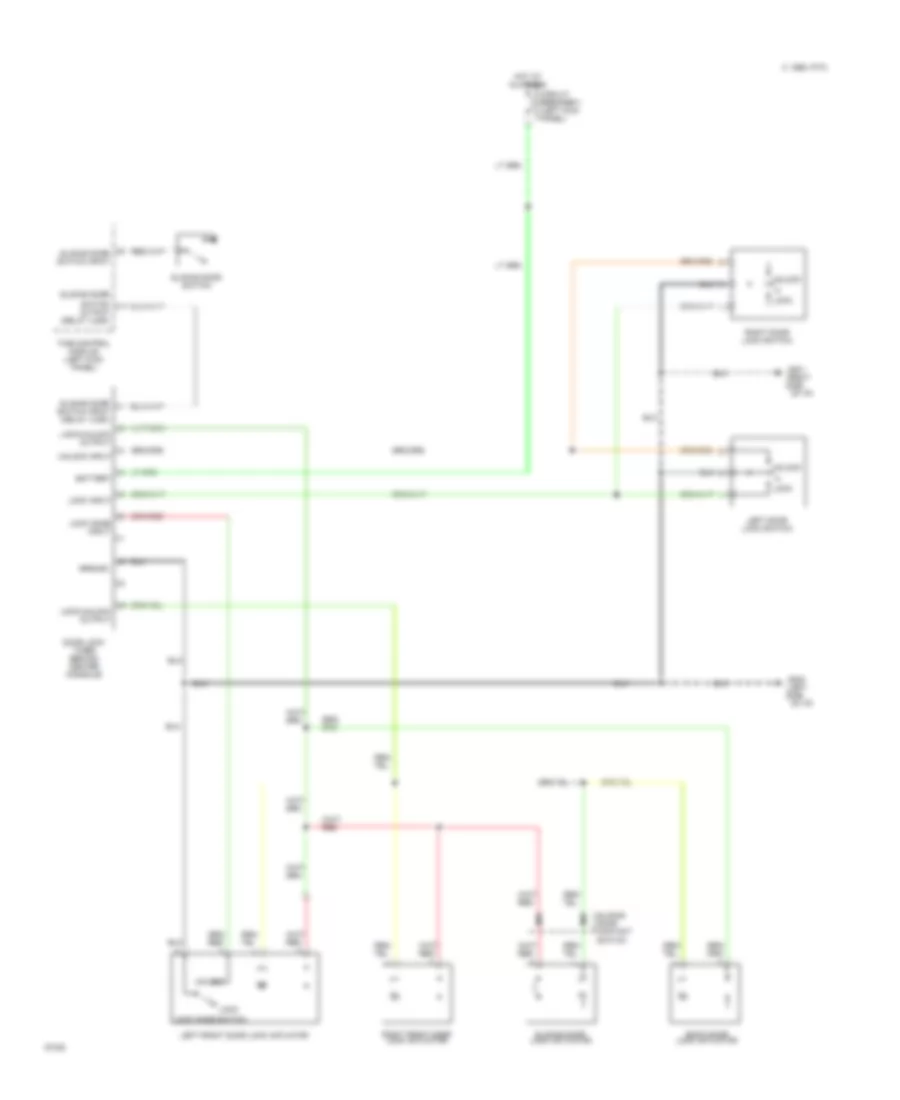
Headlight Wiring Diagram, without DRL, with Autolamps for Nissan Quest GXE 1994
 https://portal-diagnostov.com/license.html
Automotive Electricians Portal FZCO
Automotive Electricians Portal FZCO
https://portal-diagnostov.com/license.html
https://portal-diagnostov.com/license.html
Automotive Electricians Portal FZCO
Automotive Electricians Portal FZCOList of elements for Headlight Wiring Diagram, without DRL, with Autolamps for Nissan Quest GXE 1994:
- (left side of dash) smj
- (right side of engine compt)
- A10
- Autolamp control module (right i/p)
- Autolamp relay 1
- Autolamp relay 2
- Autolamp sensor
- Autolamp switch
- B10
- Combination meter
- Combination switch
- Dimmer switch
- Diode j/c 1 (left i/p)
- Diode-1 (left i/p)
- Exterior lights system
- Flash -to- pass
- Fuse 4 15a
- Fuse 5 15a
- Fuse block (left kick panel)
- Fuse s 15a
- Fuse t 10a
- Fuse z 10a
- Fusible link box 1 (left front of engine compt)
- G11
- G1o2 (left front shock tower)
- G1o3 (right front shock tower)
- G202 (left i/p)
- H12
- Head
- Headlamp
- Hi beam ind.
- Hot at all times
- Hot in on or start
- I10
- Interior lights system
- Left
- Left headlamp relay
- Left relay box (behind left headlamp)
- Lighting switch
- Off
- Park
- Pnk
- Relay box
- Right
- Right headlamp
- Right headlamp relay
- Right relay box (right side of engine compt)
- Smj (left side of dash)
Headlight Wiring Diagram, without DRL, without Autolamps for Nissan Quest GXE 1994
 https://portal-diagnostov.com/license.html
Automotive Electricians Portal FZCO
Automotive Electricians Portal FZCO
https://portal-diagnostov.com/license.html
https://portal-diagnostov.com/license.html
Automotive Electricians Portal FZCO
Automotive Electricians Portal FZCOList of elements for Headlight Wiring Diagram, without DRL, without Autolamps for Nissan Quest GXE 1994:
- Combination meter
- Combination switch
- Dimmer switch
- Diode j/c 1 (left i/p)
- Exterior lights system
- Flash -to- pass
- Fuse 4 15a
- Fuse 5 15a
- Fuse block (left kick panel)
- Fuse s 15a
- Fusible link box 1 (left front of engine compt)
- G1o2 (left front shock tower)
- G1o3 (right front shock tower)
- G202 (left i/p)
- H12
- Head
- Headlamp
- Hi beam ind.
- Hot at all times
- I1 smj (left side of dash)
- Interior lights system
- Left
- Left headlamp
- Left relay box (behind left headlamp)
- Lighting switch
- Off
- Park
- Pnk
- Relay
- Right headlamp
- Right headlamp relay
- Right relay box (right side of engine compt)
- Smj (left side of dash)
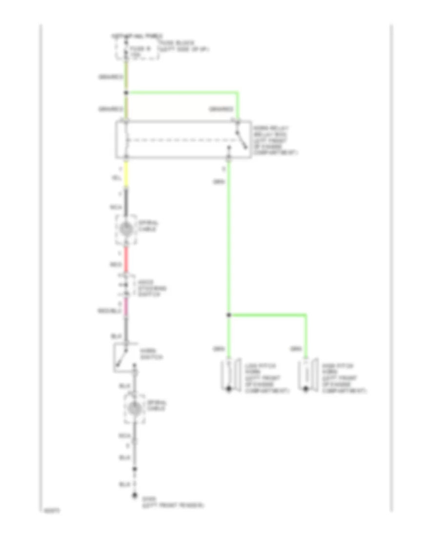
HORN
Horn Wiring Diagram for Nissan Quest GXE 1994
 https://portal-diagnostov.com/license.html
Automotive Electricians Portal FZCO
Automotive Electricians Portal FZCO
https://portal-diagnostov.com/license.html
https://portal-diagnostov.com/license.html
Automotive Electricians Portal FZCO
Automotive Electricians Portal FZCOList of elements for Horn Wiring Diagram for Nissan Quest GXE 1994:
- Ascd steering switch
- Fuse block (left side of i/p)
- Fuse r 15a
- G100 (left front fender)
- High pitch horn (left front of engine compartment)
- Horn relay (relay box, left front of engine compartment)
- Horn switch
- Hot at all times
- Low pitch horn (left front of engine compartment)
- Nca
- Red
- Spiral cable
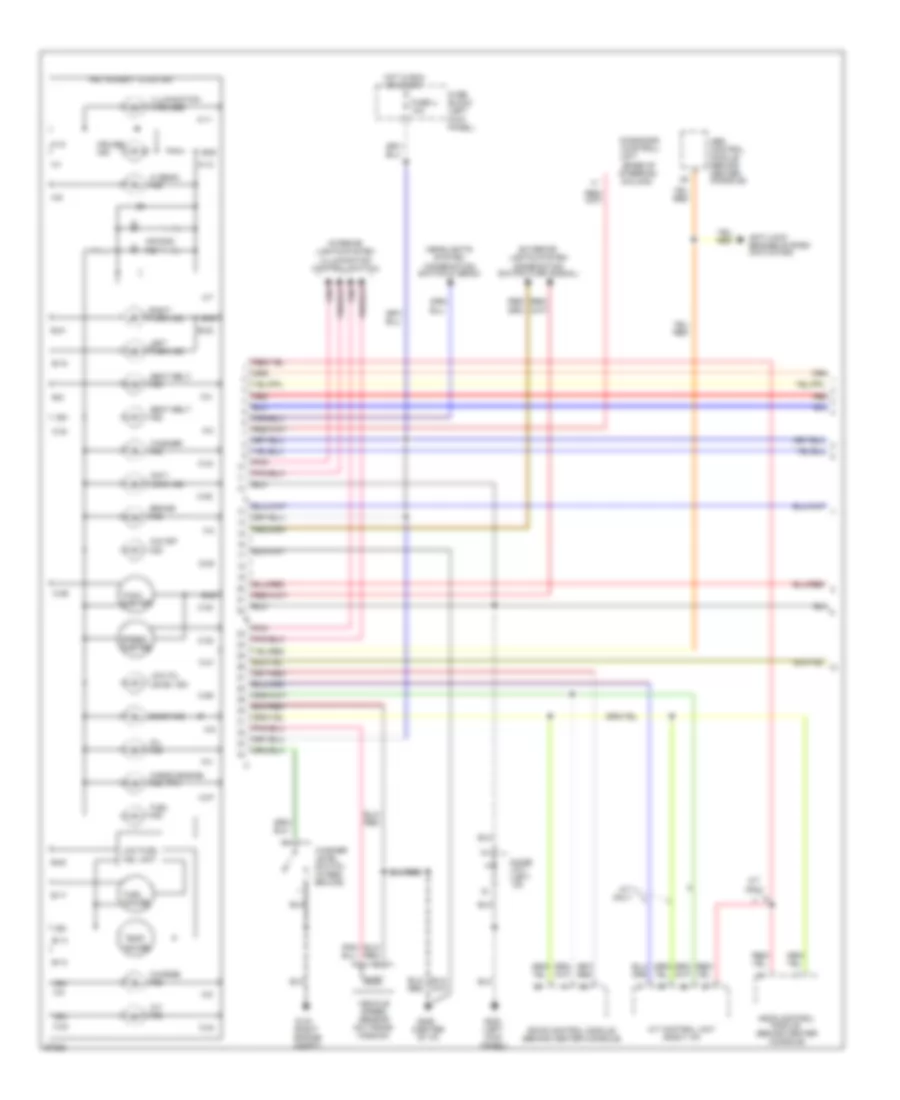
INSTRUMENT CLUSTER
Instrument Cluster Wiring Diagram (1 of 2) for Nissan Quest GXE 1994
 https://portal-diagnostov.com/license.html
Automotive Electricians Portal FZCO
Automotive Electricians Portal FZCO
https://portal-diagnostov.com/license.html
https://portal-diagnostov.com/license.html
Automotive Electricians Portal FZCO
Automotive Electricians Portal FZCOList of elements for Instrument Cluster Wiring Diagram (1 of 2) for Nissan Quest GXE 1994:
- (base of steering column)
- (center of i/p)
- (mil)
- (on trans-
- A-1
- A-10
- A-11
- A-12
- A-2
- A-3
- A-4
- A-5
- A-6
- A-7
- A-8
- A-9
- A/t control unit (right i/p)
- A/t ind.
- A/t only
- Abs control module (behind center console)
- Air bag ind.
- Anti- lock ind.
- Anti-lock brakes system (actuator)
- Ascd control module (behind center console)
- B-13
- B-14
- B-15
- B-17
- B-20
- B-21
- B-22
- B-9
- Brake ind.
- C-23
- C-24
- C-25
- C-26
- C-27
- C-29
- C-30
- C-31
- C-32
- C-33
- C-34
- Charge ind.
- Check engine ind.
- Cruise ind.
- D-28
- Diagnosis (control)
- Diode j/c-1 (left i/p)
- Door ind.
- Eccs control module (behind center console)
- Exterior lights system (combination switch-turn signal)
- Fuel gauge
- Fuel ind.
- Fuse block (left kick panel)
- Fuse u 10a
- G103 (right engine compt)
- G200 (left kick
- G206
- Gnd
- Headlights system (combination switch-hi beam)
- Hi beam ind.
- Hot in run or start
- Ign
- Illumination (4 bulbs)
- Instrument cluster
- Interior lights system (illumination control switch)
- Left turn ind.
- Low fuel ind. unit
- Low oil level ind.
- Mission)
- O/d off ind.
- Oil ind.
- Panel)
- Pnk
- Red
- Right turn ind.
- Seat belt ind.
- Speed- ometer
- Tach- ometer
- Temp. gauge
- Unit
- Vehicle speed sensor
- Washer ind.
- Washer level switch (in res- ervoir)
Instrument Cluster Wiring Diagram (2 of 2) for Nissan Quest GXE 1994
 https://portal-diagnostov.com/license.html
Automotive Electricians Portal FZCO
Automotive Electricians Portal FZCO
https://portal-diagnostov.com/license.html
https://portal-diagnostov.com/license.html
Automotive Electricians Portal FZCO
Automotive Electricians Portal FZCOList of elements for Instrument Cluster Wiring Diagram (2 of 2) for Nissan Quest GXE 1994:
- (behind left headlamp)
- (front of
- (in fuel tank)
- (in master
- (on oil pan)
- Acc
- Alternator
- Automatic seat belt control module (behind center console)
- Brake fluid level switch
- Bulb check relay
- Cylinder
- Diode j/c-1 (left i/p)
- Engine)
- Fuel tank gauge unit
- Fuse block (left kick panel)
- Fuse t 10a
- G102 (left side of engine compt)
- Hot in run or start
- Ignition switch
- Lock
- Nca
- Off
- Oil
- Oil level sensor
- Oil level timer (behind glove box)
- Parking brake switch
- Pressure
- Red
- Reservoir)
- Run
- Start
- Switch
- Thermal transmitter (top front of engine)
- Time control module (left kick panel)
INTERIOR LIGHTS
Courtesy Lamps Wiring Diagram for Nissan Quest GXE 1994
 https://portal-diagnostov.com/license.html
Automotive Electricians Portal FZCO
Automotive Electricians Portal FZCO
https://portal-diagnostov.com/license.html
https://portal-diagnostov.com/license.html
Automotive Electricians Portal FZCO
Automotive Electricians Portal FZCOList of elements for Courtesy Lamps Wiring Diagram for Nissan Quest GXE 1994:
- Acc
- Back door latch switch
- Digital touch entry control module
- Diode j/b-1 (left
- Diode j/b-1 (left i/p)
- Door
- Door warning indicator
- Front interior lamp
- Fuse block (left i/p)
- Fuse y 15a
- G102 (left front shock tower)
- G202 (left i/p)
- G998 (left rear pillar)
- Glove box lamp
- Hot at all times
- I/p)
- Ignition switch
- J/c-1 (center of i/p)
- Left foot lamp
- Left front door step lamp
- Left front door switch
- Left tailgate lamp
- Left vanity lamp
- Lock
- Map lamps
- Off
- Rear interior lamp
- Right foot lamp
- Right front door step lamp
- Right front door switch
- Right tailgate lamp
- Right vanity lamp
- Sliding door step lamp
- Sliding door switch
- Start
- Time control module (left kick panel)
Instrument Illumination Wiring Diagram for Nissan Quest GXE 1994
 https://portal-diagnostov.com/license.html
Automotive Electricians Portal FZCO
Automotive Electricians Portal FZCO
https://portal-diagnostov.com/license.html
https://portal-diagnostov.com/license.html
Automotive Electricians Portal FZCO
Automotive Electricians Portal FZCOList of elements for Instrument Illumination Wiring Diagram for Nissan Quest GXE 1994:
- (left i/p)
- A/c control module
- Ascd main switch
- Cd player
- Cigar- ette lighter
- Cluster
- Darken
- Diode j/b-1 (left i/p)
- Exterior lights system
- Fuse block (left i/p)
- Fuse s 15a
- G202 (left i/p)
- Hazard switch
- Head
- Hot at all times
- Illumination control switch (part of lighting switch)
- Instrument
- J/c-1 (center 0f i/p)
- J/c-2
- Lighten
- Lighting switch
- Off
- Park
- Pnk
- Power mode switch
- Radio
- Rear a/c control module
- Rear fan switch
- Rear remote control module
- Rear window defogger switch
- Rear wiper switch
- Time control module (left kick panel)
- W/ rear a/c
- W/ rear remote radio
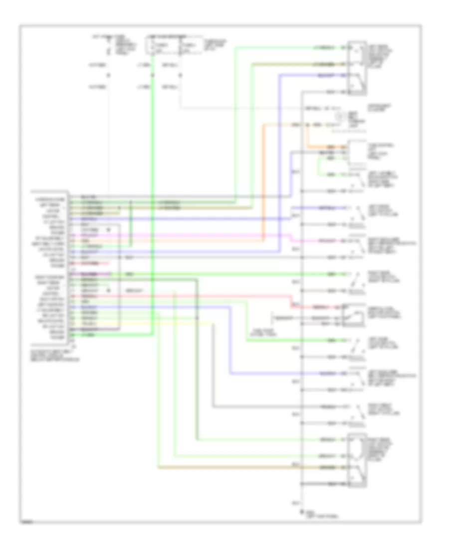
PASSIVE RESTRAINTS
Passive Restraint Wiring Diagram for Nissan Quest GXE 1994
 https://portal-diagnostov.com/license.html
Automotive Electricians Portal FZCO
Automotive Electricians Portal FZCO
https://portal-diagnostov.com/license.html
https://portal-diagnostov.com/license.html
Automotive Electricians Portal FZCO
Automotive Electricians Portal FZCOList of elements for Passive Restraint Wiring Diagram for Nissan Quest GXE 1994:
- 10a
- Automatic seat belt control module (below center console)
- Circuit breaker 2 (left kick panel)
- Control
- Fuel pump (in fuel tank)
- Fuse block (left side of i/p)
- Fuse u
- Fuse z
- G200 (left kick panel)
- Ground
- Hot at all times
- Hot in on or start
- Inertial fuel shutoff switch (left kick panel)
- Instrument cluster
- Left door latch switch (left "b" pillar)
- Left door sw
- Left front limit switch (left "a" pillar)
- Left lap belt buckle switch (right side of left seat)
- Left rear
- Left rear limit switch and motor assembly (left "b" pillar)
- Left shoulder belt retractor switch (bottom right of left seat)
- Lf limit sw
- Lr limit sw
- Lr mtr cntrl
- Lt shldr belt
- Motor
- Power
- Rf limit sw
- Right door latch switch (right "b" pillar)
- Right door sw
- Right front limit switch (right "a" pillar)
- Right rear
- Right rear limit switch and motor assembly (right "b" pillar)
- Right shoulder belt retractor switch (bottom left of right seat)
- Rr limit sw
- Rr mtr cntrl
- Rt shldr belt
- Seat belt warn
- Seat belt warning lamp
- Shut off sw
- Time control unit (left kick panel)
- Warning chime
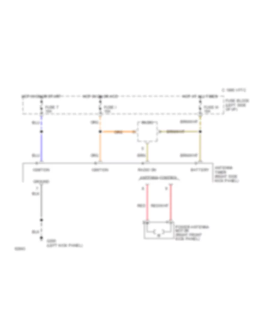
POWER ANTENNA
Power Antenna Wiring Diagram for Nissan Quest GXE 1994
 https://portal-diagnostov.com/license.html
Automotive Electricians Portal FZCO
Automotive Electricians Portal FZCO
https://portal-diagnostov.com/license.html
https://portal-diagnostov.com/license.html
Automotive Electricians Portal FZCO
Automotive Electricians Portal FZCOList of elements for Power Antenna Wiring Diagram for Nissan Quest GXE 1994:
- 1995 vftc c
- Antenna control
- Antenna timer (right side kick panel)
- Battery
- Fuse block (left side of i/p)
- Fuse i 10a
- Fuse t 10a
- Fuse w 10a
- G200 (left kick panel)
- Ground
- Hot at all times
- Hot in on or acc
- Hot in on or start
- Ignition
- Power antenna motor (right front kick panel)
- Radio
- Radio on
- Red
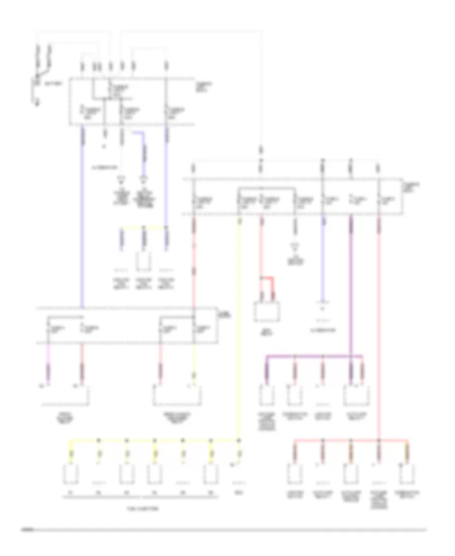
POWER DISTRIBUTION
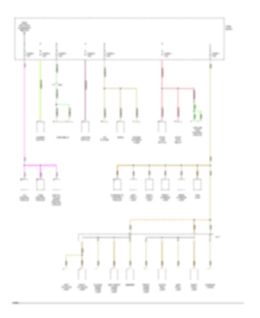
Power Distribution Wiring Diagram (1 of 4) for Nissan Quest GXE 1994
 https://portal-diagnostov.com/license.html
Automotive Electricians Portal FZCO
Automotive Electricians Portal FZCO
https://portal-diagnostov.com/license.html
https://portal-diagnostov.com/license.html
Automotive Electricians Portal FZCO
Automotive Electricians Portal FZCOList of elements for Power Distribution Wiring Diagram (1 of 4) for Nissan Quest GXE 1994:
- 100a
- 120a
- 25a
- 30a
- 45a
- 65a
- Alternator
- Autolamp control module
- Autolamp relay-1
- Battery
- Combination switch
- Cooling fan relay-1
- Cooling fan relay-2
- Cooling fan relay-3
- Daytime lamp control module (canada)
- Ecm
- Ecm relay
- Front blower relay
- Fuel injectors
- Fuse 3 10a
- Fuse 4 15a
- Fuse 5 15a
- Fuse a 20a
- Fuse b 20a
- Fuse block
- Fuse o 20a
- Fuse p 20a
- Fusible link 10
- Fusible link 11
- Fusible link 12
- Fusible link 15
- Fusible link 6
- Fusible link 7
- Fusible link 8
- Fusible link 9
- Fusible link box-1
- Fusible link box-2
- Lighting switch
- Nca
- Rear window defogger relay
- Red
- To fusible links 13&14 & fuse 1
- To ignition relay, accessory relays & fuses
- To ignition switch
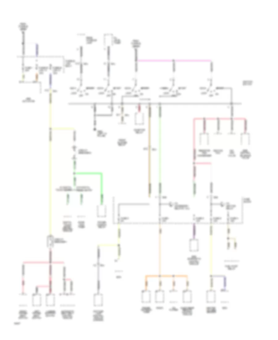
Power Distribution Wiring Diagram (2 of 4) for Nissan Quest GXE 1994
 https://portal-diagnostov.com/license.html
Automotive Electricians Portal FZCO
Automotive Electricians Portal FZCO
https://portal-diagnostov.com/license.html
https://portal-diagnostov.com/license.html
Automotive Electricians Portal FZCO
Automotive Electricians Portal FZCOList of elements for Power Distribution Wiring Diagram (2 of 4) for Nissan Quest GXE 1994:
- Abs actuator
- Acc
- Audio rear remote control module
- Automatic seat belt control module
- C12
- Cd player
- Circuit breaker-1
- Circuit breaker-2
- Condenser
- Daytime lamp control module (canada)
- Digital touch entry control module
- Door lock timer
- E11
- E12
- E45
- Ecm
- Egr control
- F12
- From fusible link 10
- From fusible link 8
- Front blower relay
- Fuel pump relay
- Fuse 1 20a
- Fuse block
- Fuse c 5a
- Fuse g 10a
- Fuse h 15a
- Fuse i 10a
- Fuse n 10a
- Fusible link 13 30a
- Fusible link 14 30a
- Fusible link box-1
- G900 (left "a" pillar)
- Heated oxygen sensor
- I12
- Iac- aac
- Ignition coil
- Ignition switch
- Inhibitor relay
- Left power seat switch
- Lock
- Lumbar support switch
- Off
- Oil level timer
- Power antenna timer
- Power window relay
- Radio
- Rear interior lamp
- Red
- Resistor and
- Right power seat switch
- Smj
- Solenoid valve
- Srs diagnostic control module
- Start
- To accessory relays 1 & 2
- To ignition relay
- Valve
- W/ digital touch entry
- W/o digital touch entry
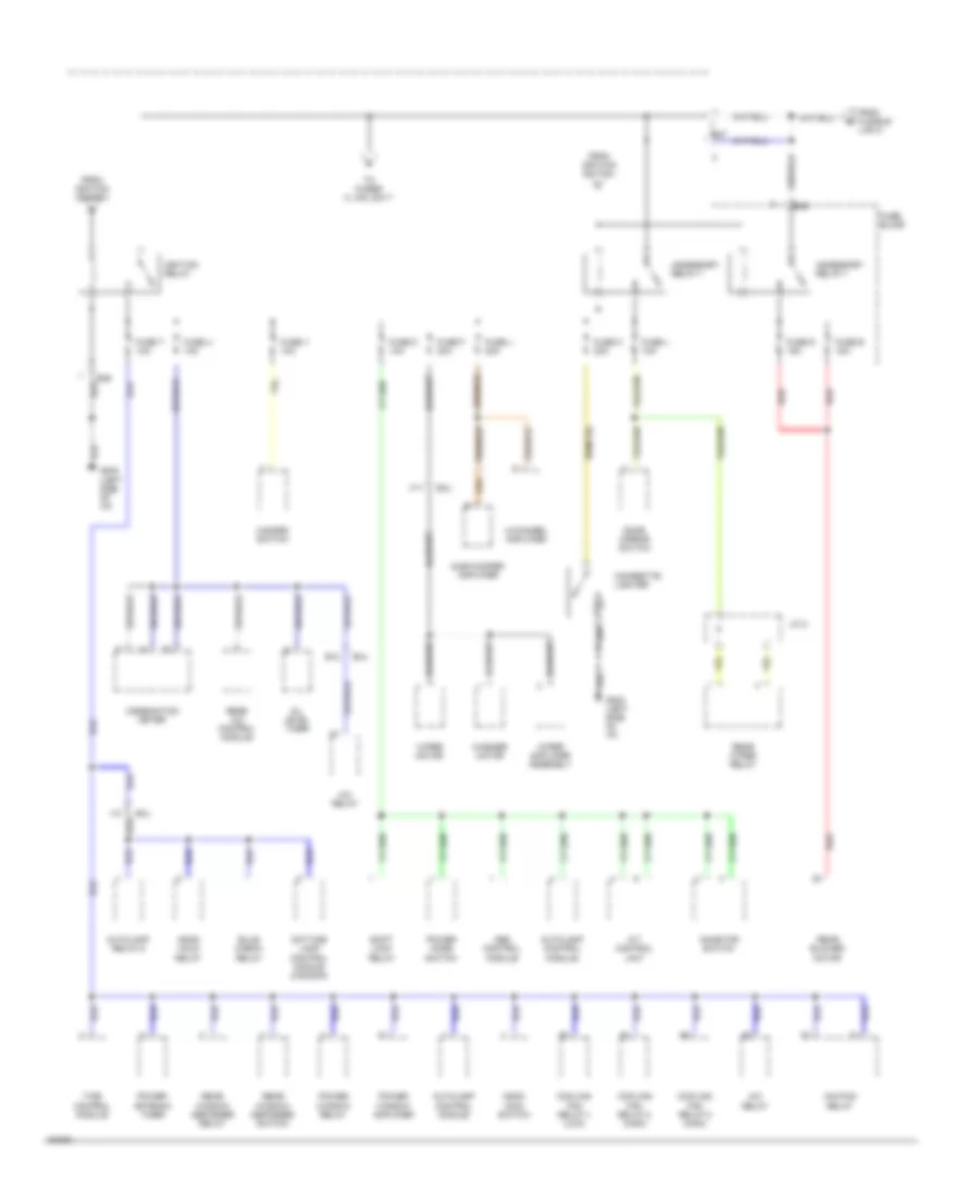
Power Distribution Wiring Diagram (3 of 4) for Nissan Quest GXE 1994
 https://portal-diagnostov.com/license.html
Automotive Electricians Portal FZCO
Automotive Electricians Portal FZCO
https://portal-diagnostov.com/license.html
https://portal-diagnostov.com/license.html
Automotive Electricians Portal FZCO
Automotive Electricians Portal FZCOList of elements for Power Distribution Wiring Diagram (3 of 4) for Nissan Quest GXE 1994:
- 4-channel amplifier
- A/c relay
- A/t control unit
- Abs control module
- Accessory relay-1
- Ascd hold relay
- Ascd main switch
- Autolamp control module
- Autolamp relay-2
- B12
- Bulb check relay
- Cigarette lighter
- Combination meter
- Cooling fan relay-1 (low)
- Cooling fan relay-2 (high)
- Cooling fan relay-3 (high)
- Daytime lamp control module (canada)
- Door mirror switch
- E45
- E46
- E47
- F11
- From fusible link 8
- From ignition switch
- Fuse block
- Fuse d 15a
- Fuse e 15a
- Fuse f 20a
- Fuse j 20a
- Fuse k 20a
- Fuse l 10a
- Fuse t 10a
- Fuse u 10a
- Fuse v 10a
- Fuse z 10a
- G202 (left side of i/p)
- Hazard switch
- I10
- Iac-ficd relay
- Ignition relay
- Inhibitor switch
- J/c 2
- Oil level timer
- Power antenna timer
- Power mode switch
- Power window amplifier
- Power window relay
- Rear a/c control module
- Rear blower motor
- Rear window defogger relay
- Rear window defogger switch
- Rear wiper relay
- Red
- Shift lock relay
- Smj
- Sub-woofer amplifier
- Time control module
- To fuses m, q-s, &w-y
- Washer motor
- Wiper amplifier assembly
- Wiper motor
Power Distribution Wiring Diagram (4 of 4) for Nissan Quest GXE 1994
 https://portal-diagnostov.com/license.html
Automotive Electricians Portal FZCO
Automotive Electricians Portal FZCO
https://portal-diagnostov.com/license.html
https://portal-diagnostov.com/license.html
Automotive Electricians Portal FZCO
Automotive Electricians Portal FZCOList of elements for Power Distribution Wiring Diagram (4 of 4) for Nissan Quest GXE 1994:
- A/t control module
- Beeper
- Cd player
- Diagnostic control module
- Digital touch entry control module
- From ignition & accessory relays
- Front door step lamp
- Front interior lamp
- Fuse block
- Fuse m 10a
- Fuse q 15a
- Fuse r 15a
- Fuse s 15a
- Fuse w 10a
- Fuse x 15a
- Fuse y 15a
- Glove box lamp
- Hazard switch
- Horn relay
- I11
- J/c 1
- Left foot lamp
- Left front door step lamp
- Left tailgate lamp
- Left vanity lamp
- Lighting switch
- Map lamp
- Power antenna timer
- Radio
- Rear interior lamp
- Right foot lamp
- Right tailgate lamp
- Right vanity lamp
- Shift lock relay
- Sliding door step lamp
- Smj
- Stop lamp switch
- Time control module
- Trailer tow control module
- Warning chime
POWER DOOR LOCKS
Digital Touch Entry Wiring Diagram for Nissan Quest GXE 1994
 https://portal-diagnostov.com/license.html
Automotive Electricians Portal FZCO
Automotive Electricians Portal FZCO
https://portal-diagnostov.com/license.html
https://portal-diagnostov.com/license.html
Automotive Electricians Portal FZCO
Automotive Electricians Portal FZCOList of elements for Digital Touch Entry Wiring Diagram for Nissan Quest GXE 1994:
- (delay lock)
- (left side
- (right side
- 1/2
- 1/2 input
- 3/4
- 3/4 input
- 5/6
- 5/6 input
- 7/8
- 7/8 input
- 9/0
- 9/0 input
- All dr ctrl
- Back door latch switch
- Back door lock actuator
- Back door switch input
- Back dr ctrl
- Battery
- Beeper (left front door)
- Beeper ctrl
- C 1995 vftc
- Circuit breaker-1 (left kick panel)
- Console)
- Digital touch entry control module (behind center)
- Diode j/c-1 (left
- Door open
- Door open output
- Fuse block (left i/p)
- Fuse m 10a
- Fuse y 15a
- G201
- G202
- G402 (left rear pillar)
- Ground
- Hot at all times
- I/p)
- Interior lights system
- J/c-1 (center of i/p)
- Kecm
- Key switch
- Keyboard & led
- Keypad illum.
- Left door lock switch
- Left front door lock actuator
- Left front door switch
- Lf door switch input
- Lf dr ctrl
- Lock
- Lock input
- Lock knob
- Lock knob switch
- Of i/p)
- Pnk
- Power
- Rf door switch input
- Rf/sliding dr ctrl
- Right door lock switch
- Right front door lock actuator
- Right front door switch
- Sliding door
- Sliding door (delay lock)
- Sliding door contact switch
- Sliding door lock actuator
- Sliding door switch
- Sliding door switch input
- Sw. output
- Time control module (left kick panel)
- Unlock
- Unlock input
Door Lock Wiring Diagram for Nissan Quest GXE 1994
 https://portal-diagnostov.com/license.html
Automotive Electricians Portal FZCO
Automotive Electricians Portal FZCO
https://portal-diagnostov.com/license.html
https://portal-diagnostov.com/license.html
Automotive Electricians Portal FZCO
Automotive Electricians Portal FZCOList of elements for Door Lock Wiring Diagram for Nissan Quest GXE 1994:
- Back door lock actuator
- Battery
- C 1995 vftc
- Circuit breaker-1 (left kick panel)
- Door lock timer (behind center console)
- G201 (right
- G202 (left side
- Ground
- Hot at all times
- Left door lock switch
- Left front door lock actuator
- Lock
- Lock input
- Lock knob input
- Lock knob switch
- Lock/unlock output
- Of i/p)
- Right door lock switch
- Right front door lock actuator
- Side
- Sliding door
- Sliding door contact switch
- Sliding door lock actuator
- Sliding door switch
- Sliding door switch input
- Sliding door switch input (delay lock)
- Switch output (delay lock)
- Time control module (left kick panel)
- Unlock
- Unlock input
POWER MIRRORS
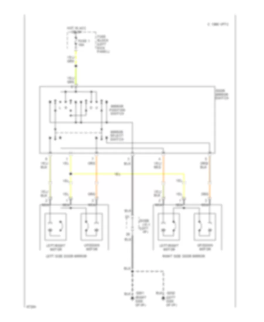
Power Mirror Wiring Diagram for Nissan Quest GXE 1994
 https://portal-diagnostov.com/license.html
Automotive Electricians Portal FZCO
Automotive Electricians Portal FZCO
https://portal-diagnostov.com/license.html
https://portal-diagnostov.com/license.html
Automotive Electricians Portal FZCO
Automotive Electricians Portal FZCOList of elements for Power Mirror Wiring Diagram for Nissan Quest GXE 1994:
- (left i/p)
- (left side of i/p)
- (right side of i/p)
- C 1995 vftc
- Diode j/c-1
- Door mirror switch
- Fuse 1 10a
- Fuse block (left kick panel)
- G201
- G202
- Hot in acc or on
- Left side door mirror
- Left/right motor
- Mirror position switch
- Mirror select switch
- Nca
- Right side door mirror
- Up/down motor
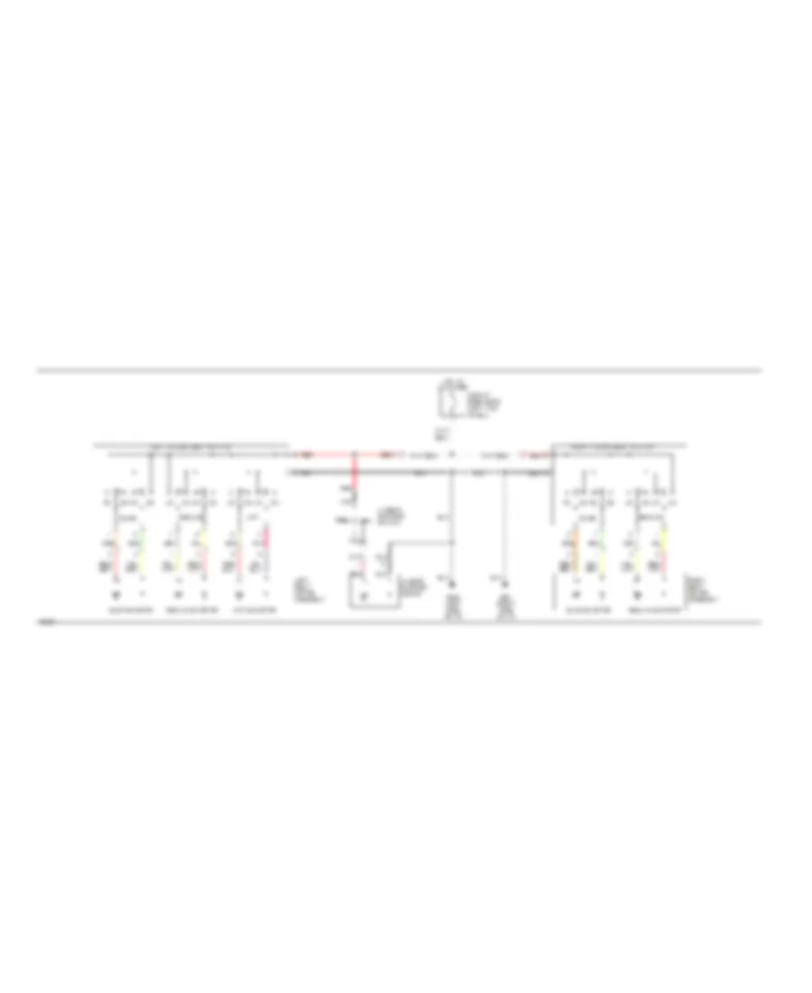
POWER SEATS
Power Seats Wiring Diagram for Nissan Quest GXE 1994
 https://portal-diagnostov.com/license.html
Automotive Electricians Portal FZCO
Automotive Electricians Portal FZCO
https://portal-diagnostov.com/license.html
https://portal-diagnostov.com/license.html
Automotive Electricians Portal FZCO
Automotive Electricians Portal FZCOList of elements for Power Seats Wiring Diagram for Nissan Quest GXE 1994:
- Circuit breaker-2 (left kick panel)
- Defl
- G201 (right side of i/p)
- G202 (left side of i/p)
- Hot at all times
- Infl
- Left power seat switch
- Left seat motor assembly
- Lift
- Lifting motor
- Lumbar support motor
- Lumbar support switch
- Nca
- Pnk
- Recline
- Reclining motor
- Red
- Right power seat switch
- Right seat motor assembly
- Slide
- Sliding motor
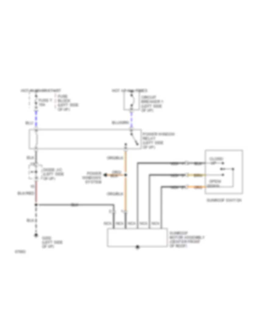
POWER TOP/SUNROOF
Power Top/Sunroof Wiring Diagrams for Nissan Quest GXE 1994
 https://portal-diagnostov.com/license.html
Automotive Electricians Portal FZCO
Automotive Electricians Portal FZCO
https://portal-diagnostov.com/license.html
https://portal-diagnostov.com/license.html
Automotive Electricians Portal FZCO
Automotive Electricians Portal FZCOList of elements for Power Top/Sunroof Wiring Diagrams for Nissan Quest GXE 1994:
- Circuit breaker 1 (left side of i/p)
- Close/
- Diode j/c (left side of i/p)
- Down
- Fuse block (left side of i/p)
- Fuse t 10a
- G202 (left side of i/p)
- Hot at all times
- Hot in on or start
- Nca
- Open/
- Power window relay (left side of i/p)
- Power windows system
- Sunroof motor assembly (center front of roof)
- Sunroof switch
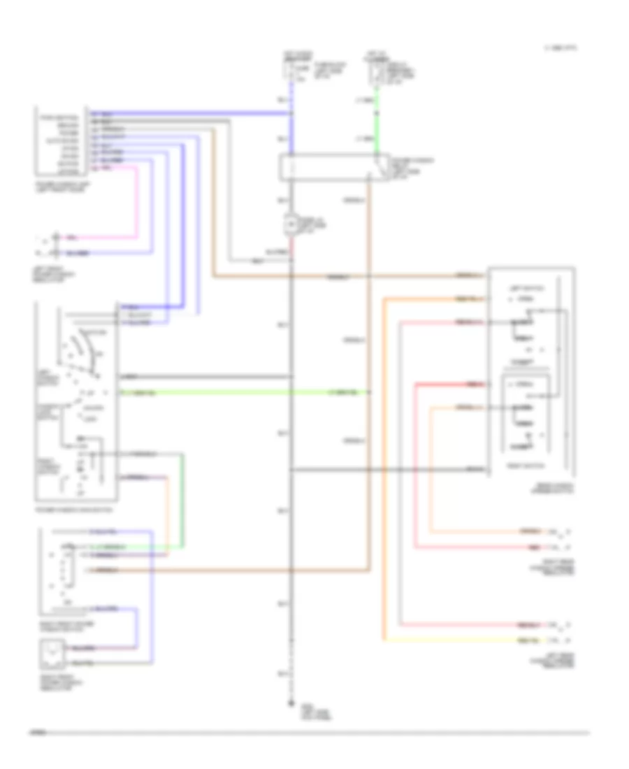
POWER WINDOWS
Power Window Wiring Diagram for Nissan Quest GXE 1994
 https://portal-diagnostov.com/license.html
Automotive Electricians Portal FZCO
Automotive Electricians Portal FZCO
https://portal-diagnostov.com/license.html
https://portal-diagnostov.com/license.html
Automotive Electricians Portal FZCO
Automotive Electricians Portal FZCOList of elements for Power Window Wiring Diagram for Nissan Quest GXE 1994:
- 1995 vftc c
- Auto dn
- Auto dn sig
- Circuit breaker 1 (left side of i/p)
- Close
- Diode j/c (left side of i/p)
- Dn pwr
- Dn sig
- Fuse t 10a
- Fuse block (left side of i/p)
- G200 (left side kick panel)
- Ground
- Hot at all times
- Hot in run or start
- Left front power window regulator
- Left rear window opener regulator
- Left switch
- Left window switch
- Lock
- Open
- Power
- Power window amp (left front door)
- Power window main switch
- Power window relay (left side of i/p)
- Pwr (ignition)
- Rear window opener switch
- Red
- Right front power window regulator
- Right front power window switch
- Right rear window opener regulator
- Right switch
- Right window switch
- Unlock
- Up pwr
- Up sig
- Window lock switch
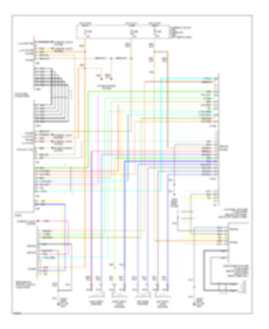
RADIO
Radio Wiring Diagrams for Nissan Quest GXE 1994
 https://portal-diagnostov.com/license.html
Automotive Electricians Portal FZCO
Automotive Electricians Portal FZCO
https://portal-diagnostov.com/license.html
https://portal-diagnostov.com/license.html
Automotive Electricians Portal FZCO
Automotive Electricians Portal FZCOList of elements for Radio Wiring Diagrams for Nissan Quest GXE 1994:
- (right rear pillar) g405
- 4-channel amplifier (if equipped) (behind trim panel, above left rear wheel)
- C/d player (if equipped)
- Fuse i 10a
- Fuse j 20a
- Fuse w 10a
- Fuse/relay block (1994) fuse block (1995) (left side of dash)
- G405 (right rear pillar)
- Ground
- Hot at all times
- Hot in acc or on
- Illum power
- Illum pwr
- Illum return
- Illum rtn
- Interior lights system
- Left front door speaker
- Left rear speaker
- M123a
- M123b
- M50
- M50a
- M54
- M55
- M56
- M56a
- Nca
- Pnk
- Power
- Power antenna system
- Pwr ant ctrl
- Radio
- Rear remote control module (if equipped)
- Right front door speaker
- Right rear speaker
- Subwoofer amplifier (if equipped) (behind trim panel, above right rear wheelwell)
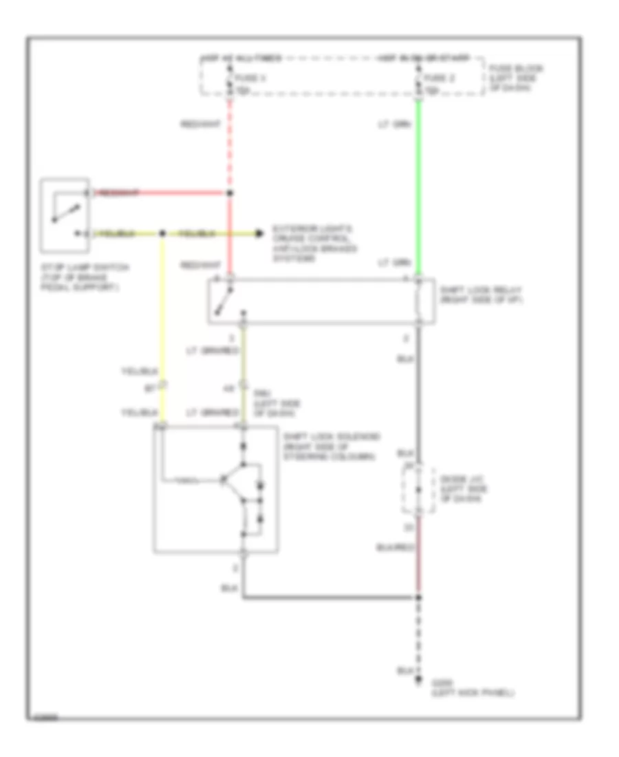
SHIFT INTERLOCKS
Shift Interlock Wiring Diagram for Nissan Quest GXE 1994
 https://portal-diagnostov.com/license.html
Automotive Electricians Portal FZCO
Automotive Electricians Portal FZCO
https://portal-diagnostov.com/license.html
https://portal-diagnostov.com/license.html
Automotive Electricians Portal FZCO
Automotive Electricians Portal FZCOList of elements for Shift Interlock Wiring Diagram for Nissan Quest GXE 1994:
- 10a
- 15a
- Diode j/c (left side of dash)
- Exterior lights, cruise control, anti-lock brakes systems
- Fuse block (left side of dash)
- Fuse x
- Fuse z
- G200 (left kick panel)
- Hot at all times
- Hot in on or start
- Shift lock relay (right side of i/p)
- Shift lock solenoid (right side of steering coloumn)
- Smj (left side of dash)
- Stop lamp switch (top of brake pedal support)
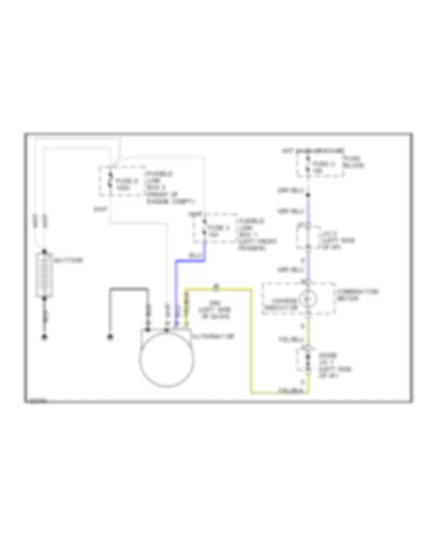
STARTING/CHARGING
Charging Wiring Diagram for Nissan Quest GXE 1994
 https://portal-diagnostov.com/license.html
Automotive Electricians Portal FZCO
Automotive Electricians Portal FZCO
https://portal-diagnostov.com/license.html
https://portal-diagnostov.com/license.html
Automotive Electricians Portal FZCO
Automotive Electricians Portal FZCOList of elements for Charging Wiring Diagram for Nissan Quest GXE 1994:
- Alternator
- Battery
- Charge indicator
- Combination meter
- Diode j/c 1 (left side of i/p)
- Fuse 3 10a
- Fuse 9 120a
- Fuse block
- Fuse u 10a
- Fusible link box 1 (left front fender)
- Fusible link box 2 (front of engine compt)
- Hot in on or start
- J/c 2 (left side of i/p)
- Nca
- Smj (left side of dash)
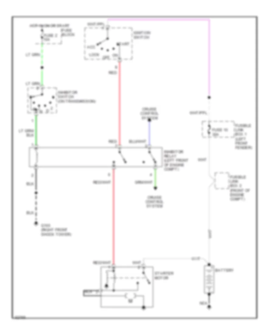
Starting Wiring Diagram for Nissan Quest GXE 1994
 https://portal-diagnostov.com/license.html
Automotive Electricians Portal FZCO
Automotive Electricians Portal FZCO
https://portal-diagnostov.com/license.html
https://portal-diagnostov.com/license.html
Automotive Electricians Portal FZCO
Automotive Electricians Portal FZCOList of elements for Starting Wiring Diagram for Nissan Quest GXE 1994:
- Acc
- Battery
- Cruise control system
- Fuse 10 30a
- Fuse block
- Fuse z 10a
- Fusible link box 1 (left front fender)
- Fusible link box 2 (front of engine compt)
- G103 (right front shock tower)
- Hot in on or start
- Ignition switch
- Inhibitor relay (left front of engine compt)
- Inhibitor switch (on transmission)
- Lock
- Nca
- Off
- Red
- Start
- Starter motor
SUPPLEMENTAL RESTRAINTS
Supplemental Restraint Wiring Diagram for Nissan Quest GXE 1994
 https://portal-diagnostov.com/license.html
Automotive Electricians Portal FZCO
Automotive Electricians Portal FZCO
https://portal-diagnostov.com/license.html
https://portal-diagnostov.com/license.html
Automotive Electricians Portal FZCO
Automotive Electricians Portal FZCOList of elements for Supplemental Restraint Wiring Diagram for Nissan Quest GXE 1994:
- Air bag diagnosis (control) module (left side of i/p)
- Air bag ind.
- Data link conn.
- Data link connector for consult (left side of i/p)
- Deployment circuit
- Diode j/c (left side of i/p)
- Eccs control module (right side of i/p)
- Front crash zone sensor (right front fender)
- Fuse block (left side of i/p)
- Fuse n 10a
- Fuse u 10a
- Fuse y 15a
- G200 (left kick panel)
- Ground
- Hot at all times
- Hot in on or start
- Instrument cluster
- Left airbag module (top of steering column)
- Left front door switch
- Nca
- Power
- Self diagn. enable
- Sensor
- Spiral cable
- Tunnel and safing sensor (below center of i/p)
- Warning lamp
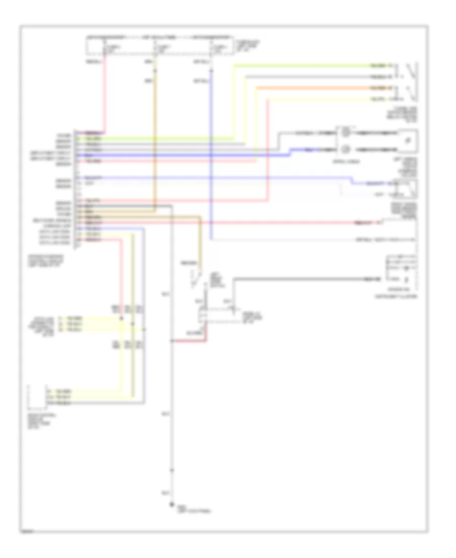
TRANSMISSION
Transmission Wiring Diagram for Nissan Quest GXE 1994
 https://portal-diagnostov.com/license.html
Automotive Electricians Portal FZCO
Automotive Electricians Portal FZCO
https://portal-diagnostov.com/license.html
https://portal-diagnostov.com/license.html
Automotive Electricians Portal FZCO
Automotive Electricians Portal FZCOList of elements for Transmission Wiring Diagram for Nissan Quest GXE 1994:
- A/t control unit (behind glove box)
- A/t fluid temp. sensor
- A/t mode switch
- All times
- Ascd control unit (behind center console)
- Automatic transaxle
- Backup lights
- Closed throttle
- Cruise
- Data link connector (for consult) (below left side of i/p)
- Dropping resistor (rear of engine)
- Eccs control module (behind glove box)
- Fuse block (left kick panel)
- Fuse m 10a
- Fuse u 10a
- Fuse z 10a
- G131 (on intake manifold)
- G200 (left kick panel)
- Hot at
- Hot in on or start
- Illum.
- Ind.
- Inhibitor switch (top of transaxle)
- Instrument cluster
- Interior lights system
- Line press. sol. valve
- Nca
- O.d. off ind.
- Od cancel switch
- Over- run clutch sol.
- Pnk
- Power ind.
- Pulse generator sensor
- Pwr
- Red
- Shift sol. valve a
- Shift sol. valve b
- Speedometer
- Tachometer
- Tcc sol. valve
- Throttle position sensor (on throttle body)
- Throttle position switch (on throttle body)
- Vehicle speed sensor (on transaxle)
- Wot
WARNING SYSTEMS
Warning System Wiring Diagrams for Nissan Quest GXE 1994
 https://portal-diagnostov.com/license.html
Automotive Electricians Portal FZCO
Automotive Electricians Portal FZCO
https://portal-diagnostov.com/license.html
https://portal-diagnostov.com/license.html
Automotive Electricians Portal FZCO
Automotive Electricians Portal FZCOList of elements for Warning System Wiring Diagrams for Nissan Quest GXE 1994:
- (behind
- (left
- Automatic seat belt control module (behind center console)
- Block (left
- C 1995 vftc
- Cluster)
- Digital touch entry control module
- Diode j/c-1
- Fuse
- Fuse i 10a
- Fuse m 10a
- Fuse s 15a
- Fuse u 10a
- Fuse y 10a
- G202 (left i/p)
- Head
- Hot at all times
- Hot in on or start
- I/p)
- Instrument
- Instrument cluster
- J/c-1 (center of i/p)
- J/c-2 (left
- Key switch
- Lap belt buckle switch
- Left front door switch
- Lighting switch
- Nca
- Off
- Park
- Pnk
- Seat belt ind.
- Time control module (left kick panel)
- Warning chime
WIPER/WASHER
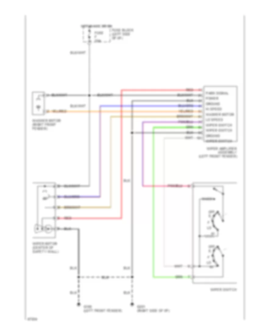
Front Wiper/Washer Wiring Diagram for Nissan Quest GXE 1994
 https://portal-diagnostov.com/license.html
Automotive Electricians Portal FZCO
Automotive Electricians Portal FZCO
https://portal-diagnostov.com/license.html
https://portal-diagnostov.com/license.html
Automotive Electricians Portal FZCO
Automotive Electricians Portal FZCOList of elements for Front Wiper/Washer Wiring Diagram for Nissan Quest GXE 1994:
- Fuse block (left side of i/p)
- Fuse f 20a
- G100 (left front fender)
- G201 (right side of i/p)
- Ground
- Hi speed
- Hot in acc or on
- Lo speed
- Off
- Park signal
- Power
- Red
- Wash
- Washer motor
- Washer motor (right front fender)
- Wiper amplifier assembly (left front fender)
- Wiper motor (center of safety wall)
- Wiper switch
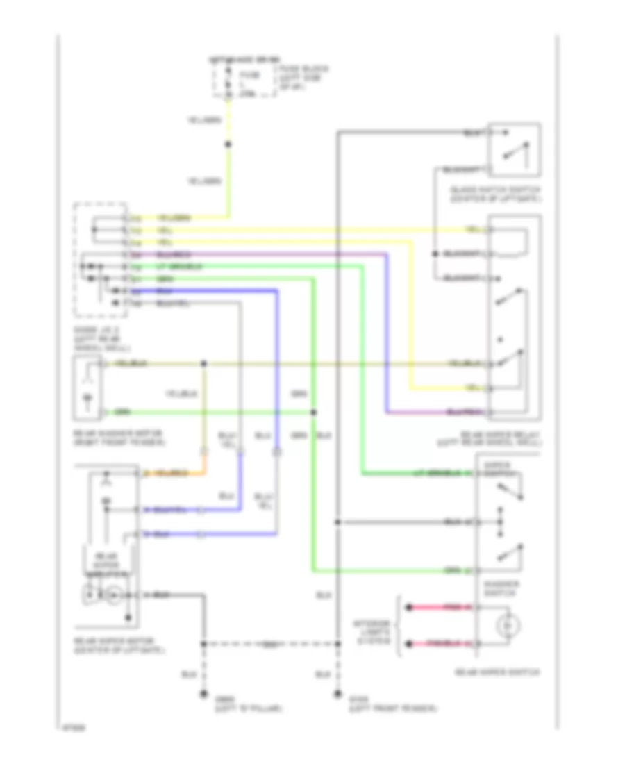
Rear Wiper/Washer Wiring Diagram, with Moveable Liftgate Glass for Nissan Quest GXE 1994
 https://portal-diagnostov.com/license.html
Automotive Electricians Portal FZCO
Automotive Electricians Portal FZCO
https://portal-diagnostov.com/license.html
https://portal-diagnostov.com/license.html
Automotive Electricians Portal FZCO
Automotive Electricians Portal FZCOList of elements for Rear Wiper/Washer Wiring Diagram, with Moveable Liftgate Glass for Nissan Quest GXE 1994:
- Diode j/c 2 (left rear wheel well)
- Fuse block (left side of i/p)
- Fuse l 10a
- G100 (left front fender)
- G999 (left "d" pillar)
- Glass hatch switch (center of liftgate)
- Hot in acc or on
- Interior lights system
- Pnk
- Rear washer motor (right front fender)
- Rear wiper amplifier
- Rear wiper motor (center of liftgate)
- Rear wiper relay (left rear wheel well)
- Rear wiper switch
- Washer switch
- Wiper switch
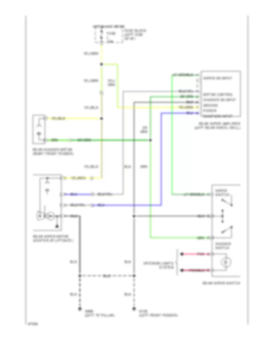
Rear Wiper/Washer Wiring Diagram, without Moveable Liftgate Glass for Nissan Quest GXE 1994
 https://portal-diagnostov.com/license.html
Automotive Electricians Portal FZCO
Automotive Electricians Portal FZCO
https://portal-diagnostov.com/license.html
https://portal-diagnostov.com/license.html
Automotive Electricians Portal FZCO
Automotive Electricians Portal FZCOList of elements for Rear Wiper/Washer Wiring Diagram, without Moveable Liftgate Glass for Nissan Quest GXE 1994:
- Fuse block (left side of i/p)
- Fuse l 10a
- G100 (left front fender)
- G999 (left "d" pillar)
- Ground
- Hot in acc or on
- Interior lights system
- Motor control
- Pnk
- Power
- Rear washer motor (right front fender)
- Rear wiper amplifier (left rear wheel well)
- Rear wiper motor (center of liftgate)
- Rear wiper switch
- Run/park input
- Washer on input
- Washer switch
- Wiper on input
- Wiper switch

 Čeština
 Dansk
Dansk Deutsch
 Ελληνικά
 English
 English
 Español
 Suomi
Suomi Français
 Français
 עברית
עברית Hrvatski
 Magyar
 Italiano
 日本語
日本語 한국어
한국어 Nederlands
 Polski
 Português
 Português
 Română
 Русский
 Slovenčina
 Slovenščina
 Svenska
 Türkçe
