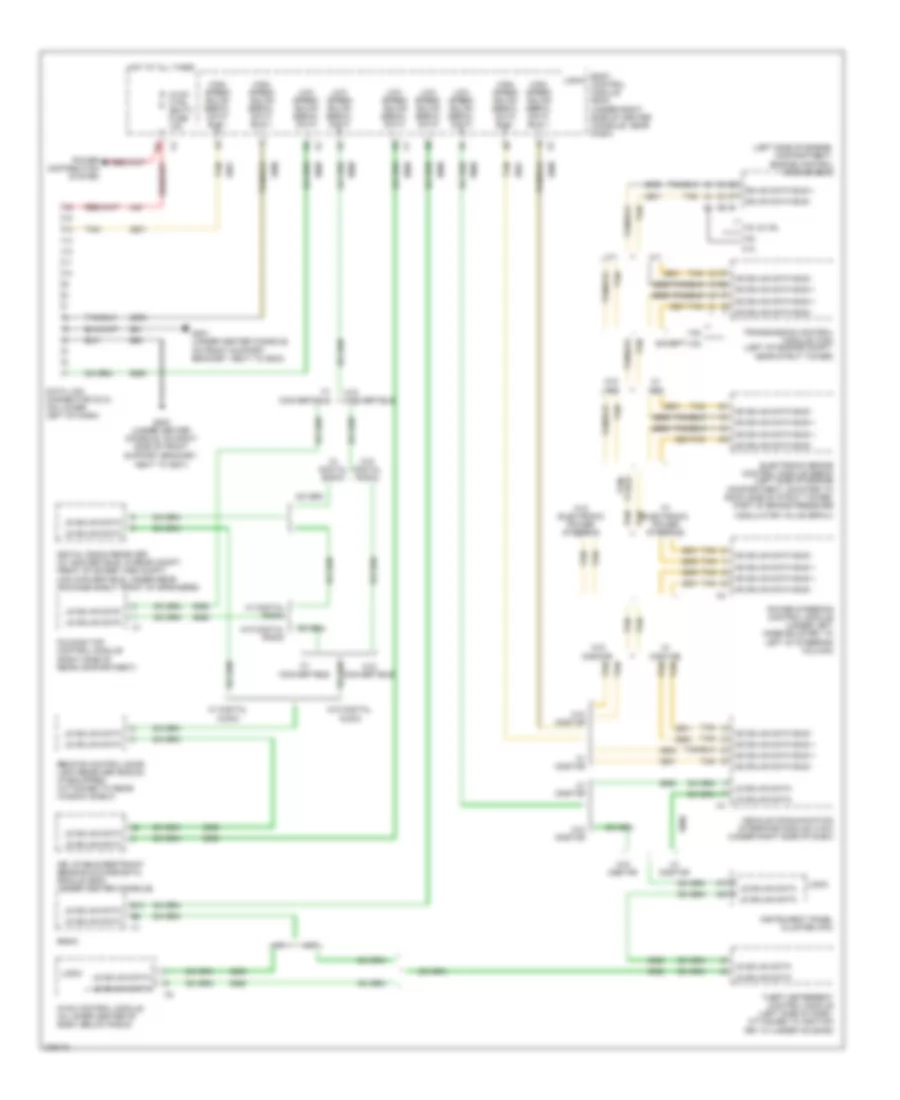
AIR CONDITIONING
Automatic A/C Wiring Diagram (1 of 2) for Pontiac G6 2008
 https://portal-diagnostov.com/license.html
Automotive Electricians Portal FZCO
Automotive Electricians Portal FZCO
https://portal-diagnostov.com/license.html
https://portal-diagnostov.com/license.html
Automotive Electricians Portal FZCO
Automotive Electricians Portal FZCO
List of elements for Automatic A/C Wiring Diagram (1 of 2) for Pontiac G6 2008:
- (right rear corner of cylinder head) (3.6l) g108
- 2.4l/3.6l
- 3.5l/3.9l
- 5 volt ref
- A/c clu fuse 1 10a
- A/c clutch relay
- A/c compressor clutch (on lower left front of engine, part of a/c compressor)
- A11 x2
- A2 x1
- Air temp dr pos sig
- Ambient air temperature sensor (on left side of front impact bar, behind grille)
- Auto
- Battery positive
- Computer data lines system
- Cool fan 1 fuse 17 30a
- Cool fan 2 fuse 18 30a
- Cool ser/par relay
- Cool/ fan 1 relay
- Cool/ fan 2 relay
- Door position sig
- Dr ctrl a
- Dr ctrl b
- E1 x2
- Fresh air ind
- G106 (except 3.6l) (3.5l: on front of engine, at transmission stud, near pnp switch) (2.4l: left rear of engine) (3.9l: left side of engine)
- G108 (3.6l) (right rear corner of cylinder head)
- G201 (under center console, on front support bracket, next to g203)
- Gnd
- High
- Hot at all times
- Hot in run or start
- Hvac control module (in lower center of dash, below radio)
- Ign 3 vol
- Interior lights system
- Left engine cooling fan (left front of engine compt, mounted to left side of radiator)
- Logic
- Low blower motor switch
- Low ref
- Lower air temperature sensor (under right side of console access panel)
- Mode dr pos sig
- Mode switch
- Off
- Recir door ctrl
- Recirculation ind
- Recirculation switch
- Req sig
- Right engine cooling fan (right front of engine compt, mounted to right side of radiator)
- Serial data
- Signal
- Tan
- Temperature control switch
- Underhood fuse block (in left side of engine compt)
- Upper air temperature sensor (behind left center of a/c vent)
- X1 e3
- X3 b9
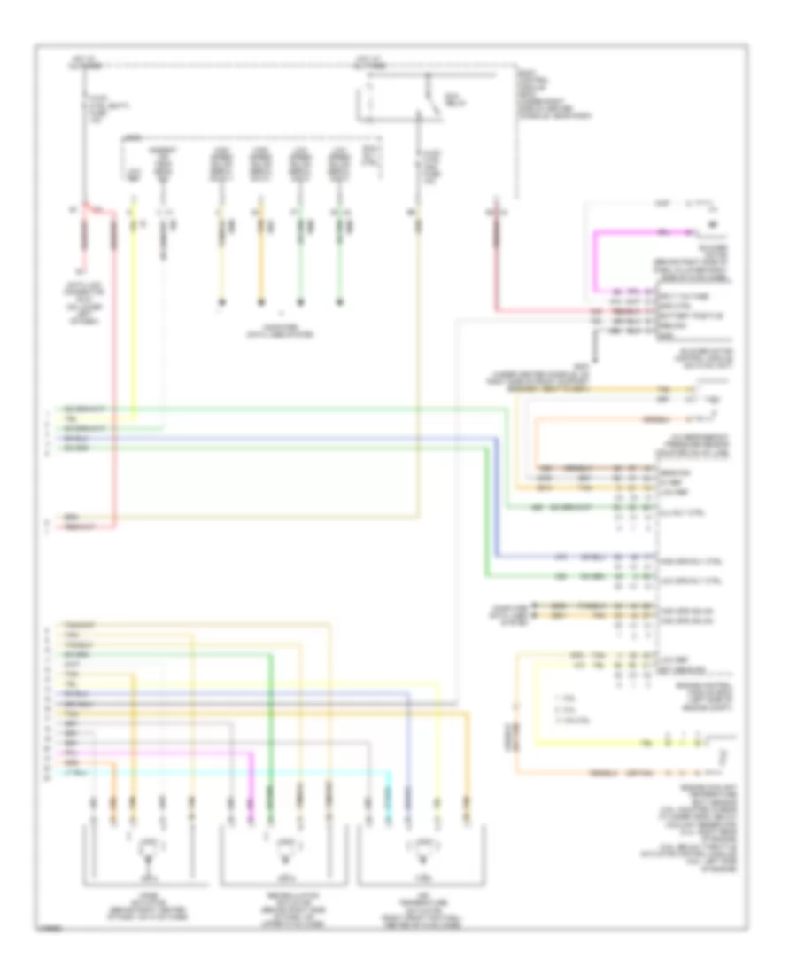
Automatic A/C Wiring Diagram (2 of 2) for Pontiac G6 2008
 https://portal-diagnostov.com/license.html
Automotive Electricians Portal FZCO
Automotive Electricians Portal FZCO
https://portal-diagnostov.com/license.html
https://portal-diagnostov.com/license.html
Automotive Electricians Portal FZCO
Automotive Electricians Portal FZCOList of elements for Automatic A/C Wiring Diagram (2 of 2) for Pontiac G6 2008:
- (or tan)
- 2.4l
- 3.5l/3.9l
- 3.6l
- 5v ref
- A/c refrigerant pressure sensor (mounted on a/c line)
- Air temperature actuator (right front footwell center of hvac case)
- Ambient air temp sens sig
- Battery positive
- Blower motor (behind right side of dash, in lower right side of hvac case)
- Blower motor control module (on hvac unit)
- Body control module (bcm) (under right side of center console, near dash)
- Clu rly ctrl
- Computer data lines system
- Data link connector (dlc) (on lower left of dash)
- E2 x4
- Ect sens sig
- Engine control module (ecm) (left side of engine compt)
- Engine coolant temperature (ect) sensor (3.5l: mounted in rear cylinder head, below coolant reservoir) (2.4l: right rear of engine) (3.9l: below throttle actuator control module) (3.6l: left side of engine)
- G203 (under center console, on right side of front support bracket, next to g201)
- Gnd
- High spd gmlan
- High spd rly ctrl
- High speed gmlan serial data +
- High speed gmlan serial data -
- Hot at all times
- Hvac ctrl (batt) fuse 10a
- Hvac ctrl (ign) fuse 10a
- Logic
- Low ref
- Low spd rly ctrl
- Low speed gmlan serial data
- Mode actuator (behind right center of dash, on hvac case)
- Recirculation actuator (behind right side of dash, on upper hvac case)
- Req sig
- Run relay
- Run rly ctrl
- Sens sig
- Spd ctrl
- Sply voltage
- Tan
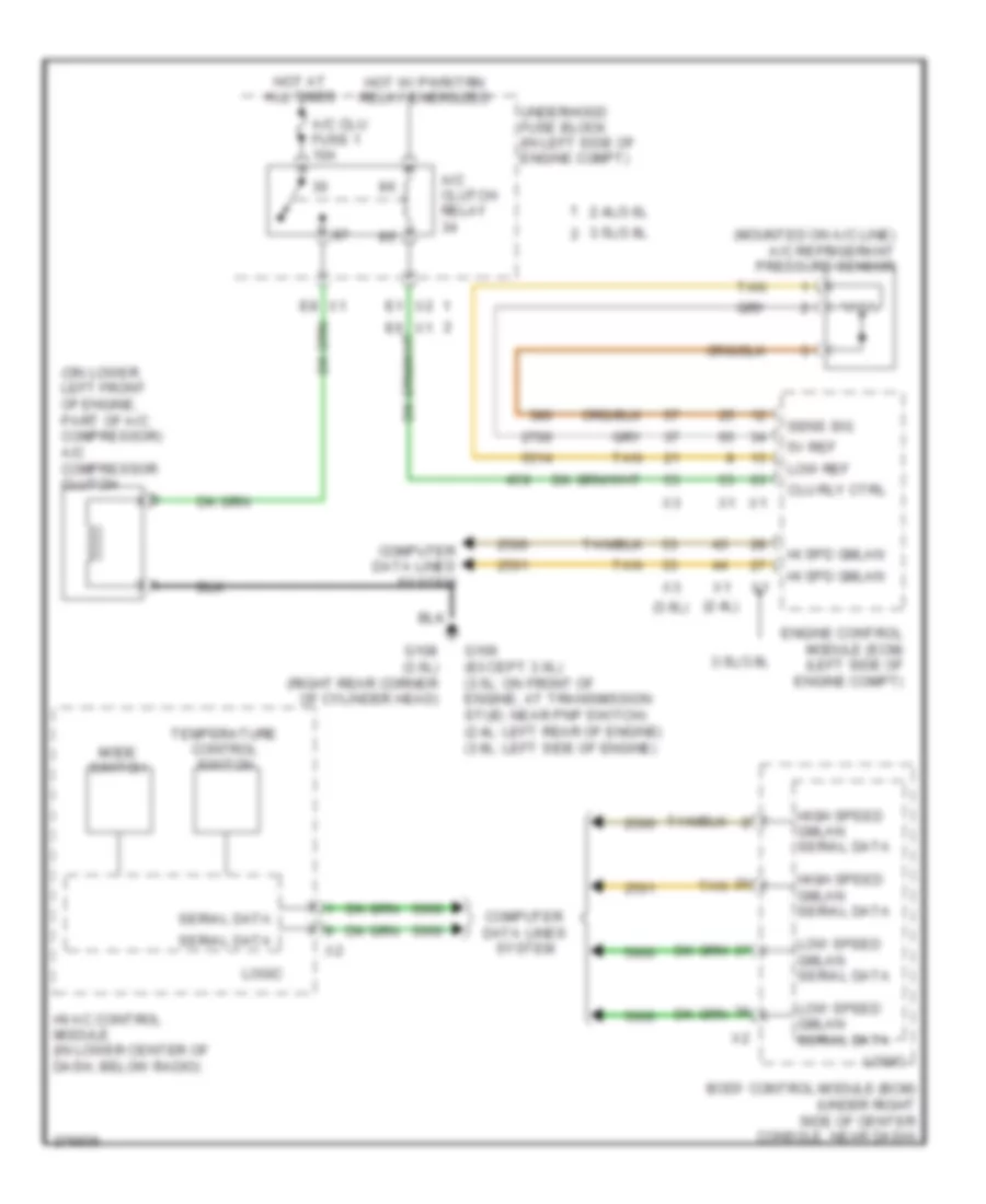
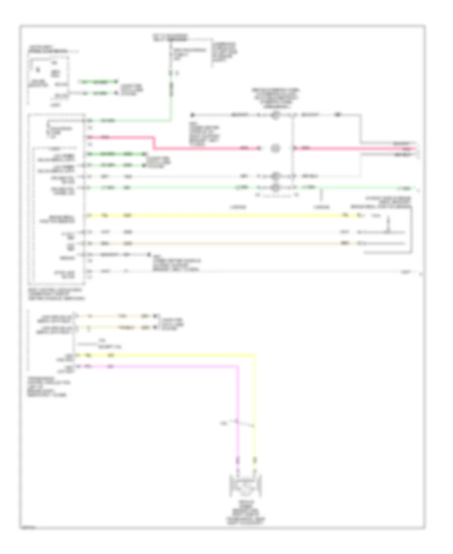
Compressor Wiring Diagram, with Auto A/C for Pontiac G6 2008
 https://portal-diagnostov.com/license.html
Automotive Electricians Portal FZCO
Automotive Electricians Portal FZCO
https://portal-diagnostov.com/license.html
https://portal-diagnostov.com/license.html
Automotive Electricians Portal FZCO
Automotive Electricians Portal FZCOList of elements for Compressor Wiring Diagram, with Auto A/C for Pontiac G6 2008:
- (2.4l)
- (3.6l)
- (mounted on a/c line) a/c refrigerant pressure sensor
- (on lower left front of engine, part of a/c compressor) a/c compressor clutch
- 2.4l/3.6l
- 3.5l/3.9l
- 5v ref
- A/c clu fuse 1 10a
- A/c clutch relay
- Body control module (bcm) (under right side of center console, near dash)
- Clu rly ctrl
- Computer data lines system
- Engine control module (ecm) (left side of engine compt)
- G106 (except 3.6l) (3.5l: on front of engine, at transmission stud, near pnp switch) (2.4l: left rear of engine) (3.9l: left side of engine)
- G108 (3.6l) (right rear corner of cylinder head)
- Hi spd gmlan
- High speed gmlan serial data
- Hot at all times
- Hot w/ pwr/trn relay energized
- Hvac control module (in lower center of dash, below radio)
- Logic
- Low ref
- Low speed gmlan serial data
- Mode switch
- Sens sig
- Serial data
- Tan
- Temperature control switch
- Underhood fuse block (in left side of engine compt)
- X1 e8
- X2 e1
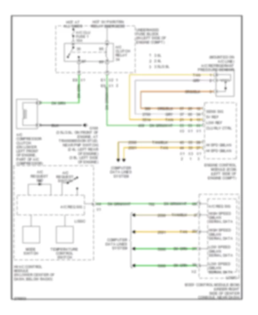
Compressor Wiring Diagram, with Manual A/C for Pontiac G6 2008
 https://portal-diagnostov.com/license.html
Automotive Electricians Portal FZCO
Automotive Electricians Portal FZCO
https://portal-diagnostov.com/license.html
https://portal-diagnostov.com/license.html
Automotive Electricians Portal FZCO
Automotive Electricians Portal FZCOList of elements for Compressor Wiring Diagram, with Manual A/C for Pontiac G6 2008:
- (mounted on a/c line) a/c refrigerant pressure sensor
- 2.4l
- 3.5l/3.9l
- 3.6l
- 5v ref
- A/c clu fuse 1 10a
- A/c clutch relay
- A/c compressor clutch (on lower left front of engine, part of a/c compressor)
- A/c req sig
- A/c request ind
- A/c request switch
- Body control module (bcm) (under right side of center console, near dash)
- Clu rly ctrl
- Computer data lines system
- E1 x2
- E8 x1
- Engine control module (ecm) (left side of engine compt)
- G106 (3.5l/3.6l: on front of engine, at transmission stud, near pnp switch) (2.4l: left rear of engine) (3.9l: left side of engine)
- Hi spd gmlan
- High speed gmlan serial data
- Hot at all times
- Hot w/ pwr/trn relay energized
- Hvac control module (in lower center of dash, below radio)
- Logic
- Low ref
- Low speed gmlan serial data
- Mode switch
- Sens sig
- Tan
- Temperature control switch
- Underhood fuse block (in left side of engine compt)
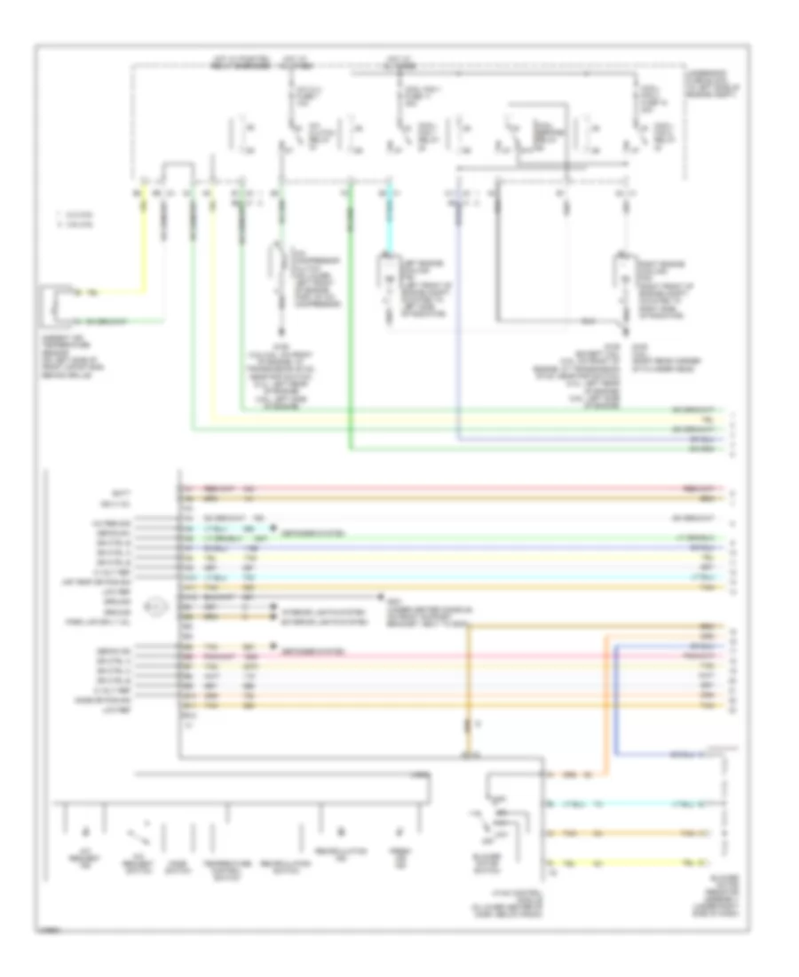
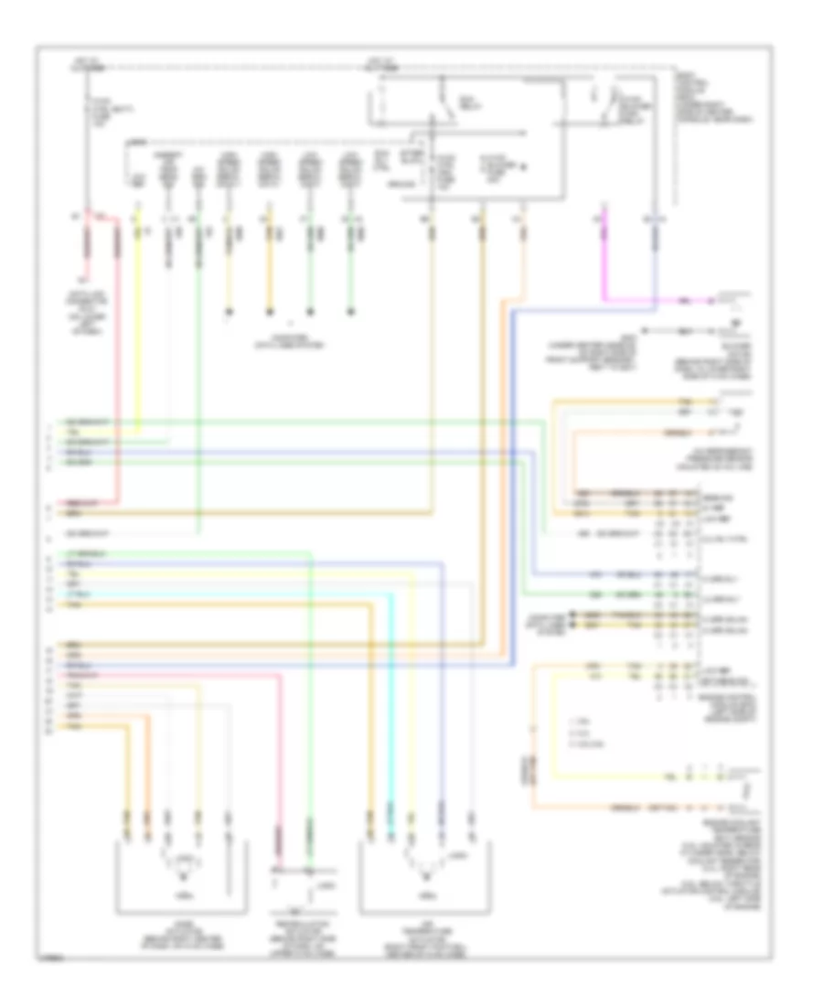
Manual A/C Wiring Diagram (1 of 2) for Pontiac G6 2008
 https://portal-diagnostov.com/license.html
Automotive Electricians Portal FZCO
Automotive Electricians Portal FZCO
https://portal-diagnostov.com/license.html
https://portal-diagnostov.com/license.html
Automotive Electricians Portal FZCO
Automotive Electricians Portal FZCOList of elements for Manual A/C Wiring Diagram (1 of 2) for Pontiac G6 2008:
- 2.4l/3.6l
- 3.5l/3.9l
- 5 volt ref
- 87a
- A/c clu fuse 1 10a
- A/c clutch relay
- A/c compressor clutch (on lower left front of engine, part of a/c compressor)
- A/c req sig
- A/c request ind
- A/c request switch
- A10
- A11
- A11 x2
- A12
- A2 x1
- Air temp dr pos sig
- Ambient air temperature sensor (on left side of front impact bar, behind grille)
- B10
- B11
- B12
- B9 x3
- Batt
- Blower motor resistor assembly (under right side of dash)
- Blower motor switch
- Cool fan 1 fuse 17 30a
- Cool ser/par relay
- Cool/ fan 1 relay
- Cool/ fan 2 fuse 18 30a
- Cool/ fan 2 relay
- Defog ind
- Defog sw
- Defogger system
- Dr ctrl a
- Dr ctrl b
- E1 x2
- Exterior lights system
- Fresh air ind
- G106 (3.5l/3.6l: on front of engine, at transmission stud, near pnp switch) (2.4l: left rear of engine) (3.9l: left side of engine)
- G106 (except 3.6l) (3.5l: on front of engine, at transmission stud, near pnp switch) (2.4l: left rear of engine) (3.9l: left side of engine)
- G108 (3.6l) (right rear corner of cylinder head)
- G201 (under center console, on front support bracket, next to g203)
- Ground
- High
- Hot at all times
- Hot w/ pwr/trn relay energized
- Hvac control module (in lower center of dash, below radio)
- Ign 3 vol
- Interior lights system
- Left engine cooling fan (left front of engine compt, mounted to left side of radiator)
- Logic
- Low
- Low ref
- Mode dr pos sig
- Mode switch
- Off
- Park lmp sply vol
- Recirculation ind
- Recirculation switch
- Right engine cooling fan (right front of engine compt, mounted to right side of radiator)
- Tan
- Temperature control switch
- Underhood fuse block (in left side of engine compt)
- X1 e3
- X2 g
Manual A/C Wiring Diagram (2 of 2) for Pontiac G6 2008
 https://portal-diagnostov.com/license.html
Automotive Electricians Portal FZCO
Automotive Electricians Portal FZCO
https://portal-diagnostov.com/license.html
https://portal-diagnostov.com/license.html
Automotive Electricians Portal FZCO
Automotive Electricians Portal FZCOList of elements for Manual A/C Wiring Diagram (2 of 2) for Pontiac G6 2008:
- (or tan)
- 2.4l
- 3.5l/3.9l
- 3.6l
- 5v ref
- A/c refrigerant pressure sensor (mounted on a/c line)
- A/c req sig
- After blow
- Air temperature actuator (right front footwell center of hvac case)
- Ambient air temp sens sig
- Blower motor (behind right side of dash, in lower right side of hvac case)
- Body control module (bcm) (under right side of center console, near dash)
- Clu rly ctrl
- Computer data lines system
- Data link connector (dlc) (on lower left of dash)
- E3 x4
- Ect sens sig
- Engine control module (ecm) (left side of engine compt)
- Engine coolant temperature (ect) sensor (3.5l: mounted in rear cylinder head, below coolant reservoir) (2.4l: right rear of engine) (3.9l: below throttle actuator control module) (3.6l: left side of engine)
- G203 (under center console, on right side of front support bracket, next to g201)
- Ground
- Hi spd gmlan
- Hi spd rly
- High speed gmlan serial data +
- High speed gmlan serial data -
- Hot at all times
- Hvac blower fuse 20a
- Hvac blower high relay
- Hvac ctrl (batt) fuse 10a
- Hvac ctrl (ign) fuse 10a
- Lo spd rly
- Logic
- Low ref
- Low speed gmlan serial data
- Mode actuator (behind right center of dash, on hvac case)
- Recirculation actuator (behind right side of dash, on upper hvac case)
- Run relay
- Run rly ctrl
- Sens sig
- Tan
ANTI-LOCK BRAKES
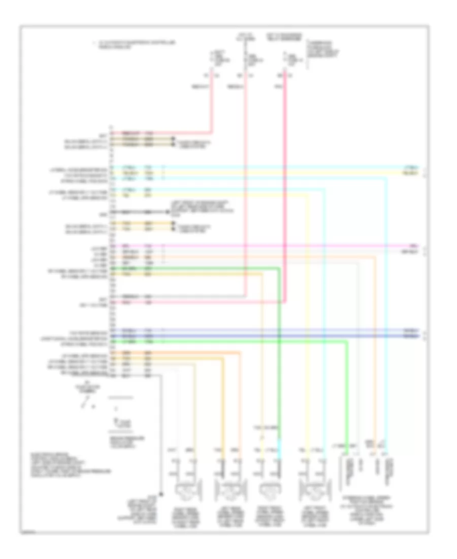
Anti-lock Brakes Wiring Diagram (1 of 2) for Pontiac G6 2008
 https://portal-diagnostov.com/license.html
Automotive Electricians Portal FZCO
Automotive Electricians Portal FZCO
https://portal-diagnostov.com/license.html
https://portal-diagnostov.com/license.html
Automotive Electricians Portal FZCO
Automotive Electricians Portal FZCOList of elements for Anti-lock Brakes Wiring Diagram (1 of 2) for Pontiac G6 2008:
- (left front of engine compt, on left rear side of core support, between g101 & g104) g109
- 5v ref
- Abs fuse 15 10a
- Abs fuse 24 60a
- B+ pump motor control
- Bat
- Batt abs fuse 55 30a
- Brake pressure modulator valve (bpmv)
- Computer data lines system
- Electronic brake control module (ebcm) (left side of engine compt, mounted to back side of strut tower, part of brake pressure modulator valve (bpmv))
- G109 (left front of engine compt, on left rear side of core support, between g101 & g104)
- Gmlan serial data (+)
- Gmlan serial data (-)
- Gnd
- Hot at all times
- Hot w/ run/crank relay energized
- Ign 1 voltage
- Lateral accelerometer sig
- Left front wheel speed sensor (wss) (in left front wheel hub)
- Left rear wheel speed sensor (wss) (in left rear wheel hub)
- Lf wheel sens sply voltage
- Lf wheel spd sens sig
- Longitudinal accelerometer sig
- Low ref
- Lr wheel sens sply voltage
- Lr wheel spd sens sig
- Nca
- Pnk
- Pump motor
- Rf wheel sens sply voltage
- Rf wheel spd sens sig
- Right front wheel speed sensor (wss) (in right front wheel hub)
- Right rear wheel speed sensor (wss) (in right rear wheel hub)
- Rr wheel sens sply voltage
- Rr wheel spd sens sig
- Steering wheel speed/ position sensor (w/ automatic electronic controlled ride & handling) (under left side of dash)
- Strng wheel pos sig a
- Strng wheel pos sig b
- Tan
- Underhood fuse block (in left side of engine compt)
- W/ automatic electronic controlled ride & handling
- Yaw rate diagnostic
- Yaw rate sens sig
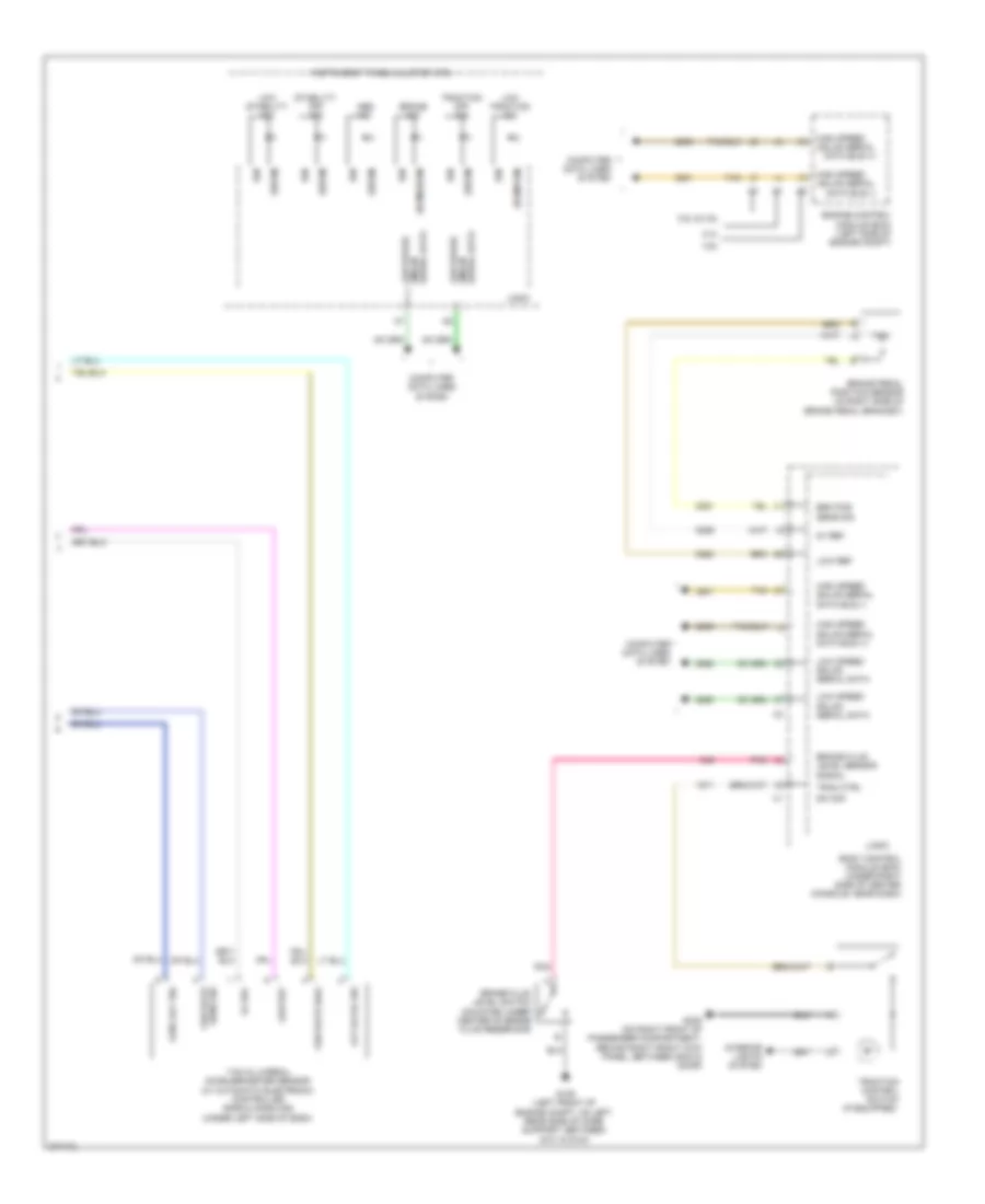
Anti-lock Brakes Wiring Diagram (2 of 2) for Pontiac G6 2008
 https://portal-diagnostov.com/license.html
Automotive Electricians Portal FZCO
Automotive Electricians Portal FZCO
https://portal-diagnostov.com/license.html
https://portal-diagnostov.com/license.html
Automotive Electricians Portal FZCO
Automotive Electricians Portal FZCOList of elements for Anti-lock Brakes Wiring Diagram (2 of 2) for Pontiac G6 2008:
- (bcm/ebcm)
- (ebcm)
- (ecm/pcm)
- (if equipped)
- 2.4l
- 3.5l & 3.9l
- 3.6l
- 5v ref
- Abs ind
- Body control module (bcm) (under right side of center console, near dash)
- Brake fluid level sensor signal
- Brake fluid level switch (mounted under center of brake fluid reservoir)
- Brake ind
- Brake pedal position sensor (in right side of brake pedal bracket)
- Brk pos sens sig
- Computer data lines system
- Engine control module (ecm) (left side of engine compt)
- G109 (left front of engine compt, on left rear side of core support, between g101 & g104)
- G305 (on right front of passenger compartment, behind right front kick panel, between g304 & door)
- Gmlan serial data bus (+)
- Gmlan serial data bus (-)
- High speed
- High speed gmlan serial data bus (+)
- High speed gmlan serial data bus (-)
- Ign
- Instrument panel cluster (ipc)
- Interior lights system
- Lat accel sig
- Logic
- Long acc sig
- Low ref
- Low speed
- Low speed gmlan
- Low speed gmlan serial data
- Low stability ind
- Low traction ind
- Pnk
- Sens sig yaw rate
- Serial data
- Serial data gmlan
- Stability off ind
- Sw sig
- Tan
- Trac ctrl
- Traction control switch
- Traction off ind
- Yaw & lateral accelerometer sensor (w/ automatic electronic controlled ride & handling) (under left side of dash)
- Yaw rate diag
ANTI-THEFT
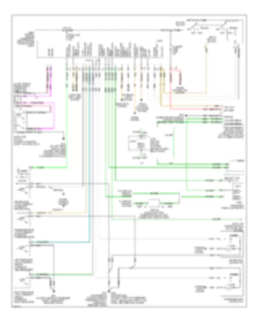
Anti-theft Wiring Diagram for Pontiac G6 2008
 https://portal-diagnostov.com/license.html
Automotive Electricians Portal FZCO
Automotive Electricians Portal FZCO
https://portal-diagnostov.com/license.html
https://portal-diagnostov.com/license.html
Automotive Electricians Portal FZCO
Automotive Electricians Portal FZCOList of elements for Anti-theft Wiring Diagram for Pontiac G6 2008:
- (in left side of engine compt) underhood fuse block
- 5v ref
- A/t
- Acc
- Acc run
- Acc volt
- Ajar
- B10
- Batt
- Battery
- Body control module (under right side of center console, near dash)
- Closed
- Cluster/ theft fuse 10a
- Cntrl park lp relay cntrl
- Computer data lines system
- Data link connector (dlc) (on lower left of dash)
- Door lock
- Door lock fuse 15a
- Driver door latch assembly (in rear of driver door)
- Driver door lock switch
- Exterior lights system
- G101 (on left rear side of core support, between windshield washer fluid reservoir & g109)
- G201 (under center console, on front support bracket, next to g203)
- G301 (coupe/sedan) (on right rear of passenger compt, under right rear seat back)
- G301 (on right rear of passenger compt, under right rear seat back)
- G305 (convertible) (on right front of passenger compt, behind right front kick panel, between g304 & door)
- Ground
- Headlights system
- Headlp high beam rel
- High spd gmlan serial data
- Hood ajar switch (in front of engine compt, on hood latch)
- Horn relay control
- Horns system
- Hot at all times
- Hvac control module (in lower center of dash, below radio)
- If equipped
- Ignition switch
- Instrument panel cluster (ipc)
- Interior lights system
- Key in ignition switch
- Key sw sig drvr dr
- Left rear door latch assembly (sedan) (in rear of left rear door)
- Lf dr ajar sw sig
- Lock
- Logic
- Low spd gmlan
- Low spd serial
- M/t
- Nca
- Off
- Off/run/ crank volt
- Passenger door latch assembly (in rear of passenger door)
- Passenger door lock switch
- Power distribution system
- Power windows system
- Psegr dr ajar sw sig
- Radio
- Right rear door latch assembly (sedan) (in rear of right rear door)
- Run
- Security ind
- Security ind sig
- Serial data
- Signal lck/unlck
- Start
- Sw sig
- Sw sig lid ajar rr compt
- Tan
- Theft deterrent control module (left side of dash, attached to ignition key cylinder housing)
- Trunk, tailgate, fuel doors system
- Unlock
- Vehicle communications interface module (vcim) (under right side of dash)
- W/ vehicle communi- cations
- W/o vehicle communi- cations
BODY CONTROL MODULES
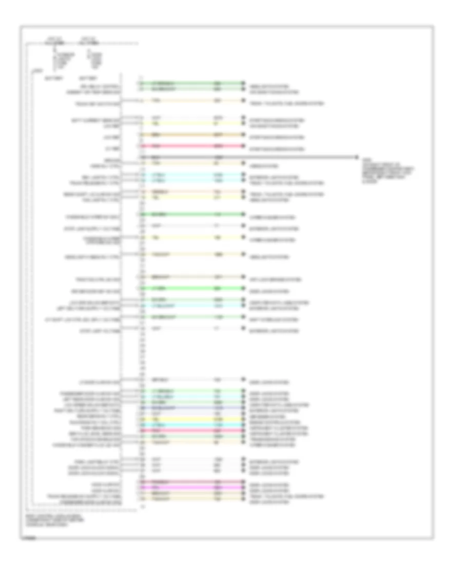
Body Control Modules Wiring Diagram (1 of 4) for Pontiac G6 2008
 https://portal-diagnostov.com/license.html
Automotive Electricians Portal FZCO
Automotive Electricians Portal FZCO
https://portal-diagnostov.com/license.html
https://portal-diagnostov.com/license.html
Automotive Electricians Portal FZCO
Automotive Electricians Portal FZCOList of elements for Body Control Modules Wiring Diagram (1 of 4) for Pontiac G6 2008:
- 5-v ref
- A/t shift lck ctrl sol sply voltage
- Air conditioning system
- Ambient air temp sens sig
- Anti-lock brakes system
- Batt current sens sig
- Battery
- Body control module (bcm) (under right side of center console, near dash)
- Brk fluid level sens sig
- Computer data lines system
- Defogger system
- Door lock fuse 15a
- Door lock/unlock signal
- Door locks system
- Driver door key sw sig
- Drl relay control
- Engine controls system
- Exterior lights system
- Fog lamp rly ctrl
- G305 (on right front of passenger compartment, behind right front kick panel, between g304 & door)
- Ground
- Headlamp hi beam rly ctrl
- Headlights system
- Hood ajar sw
- Horn rly ctrl
- Horns system
- Hot at all times
- Instrument cluster system
- Interior lights fuse 10a
- Left rear door ajar sw sig
- Lf door ajar sw sig
- Logic
- Low ref
- Low spd gmlan ser data
- Low speed gmlan ser data
- Park brake sw sig
- Park lamp relay ctrl
- Passenger door ajar sw sig
- Pnk
- Rear compt lid ajar sw sig
- Rear defog rly ctrl
- Rev lamp rly ctrl
- Run/crank rly coil ctrl
- Shift interlock system
- Starting/charging system
- Stop lamp voltage
- Tan
- Tap/up/down enable sig
- Traction ctrl sw sig
- Transmissions system
- Trunk key switch sig
- Trunk release rly ctrl
- Trunk, tailgate, fuel doors system
- Windshield washer fluid lev sig
- Windshield wiper mtr park sw sig
- Windshield wiper sw sig 2
- Wiper/washer system
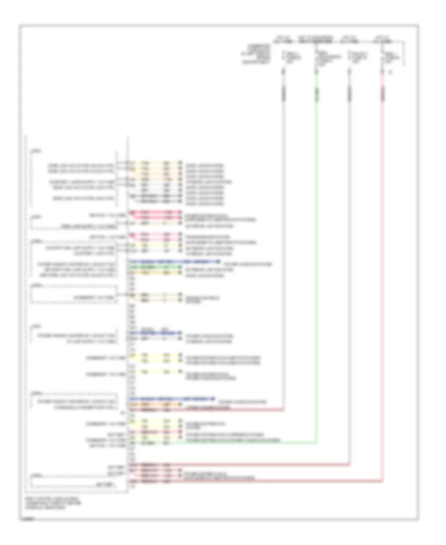
Body Control Modules Wiring Diagram (2 of 4) for Pontiac G6 2008
 https://portal-diagnostov.com/license.html
Automotive Electricians Portal FZCO
Automotive Electricians Portal FZCO
https://portal-diagnostov.com/license.html
https://portal-diagnostov.com/license.html
Automotive Electricians Portal FZCO
Automotive Electricians Portal FZCOList of elements for Body Control Modules Wiring Diagram (2 of 4) for Pontiac G6 2008:
- (or 243)
- (under right side of center console, near dash)
- A10
- A11
- A12
- Accessory voltage
- B10
- B11
- B12
- Battery
- Body control module (bcm)
- C11
- C12
- Courtesy lamp ctrl
- D10
- D11
- D12
- Door lock actuator lock ctrl
- Door lock actuator unlock ctrl
- Door locks system
- Drr door lock actuator unlock ctrl
- Engine controls system
- Exterior lights system
- Hot at all times
- Hot w/ run/crank relay energized
- Ibcm (run/crank) fuse 21 30a
- Ibcm 1 fuse 20 30a
- Ibcm 2 fuse 25 50a
- Ignition 1 voltage
- Interior lights system
- Logic
- Pnk
- Power distribution & mirrors systems
- Power distribution & power windows systems
- Power distribution & seats systems
- Power distribution system
- Power window master sw lockout sig
- Power windows system
- Run rly fuse 19 30a
- Tan
- Transmissions system
- Underhood fuse block (in left side of engine compartment)
- Windshield washer pump ctrl
- Wiper/washer system
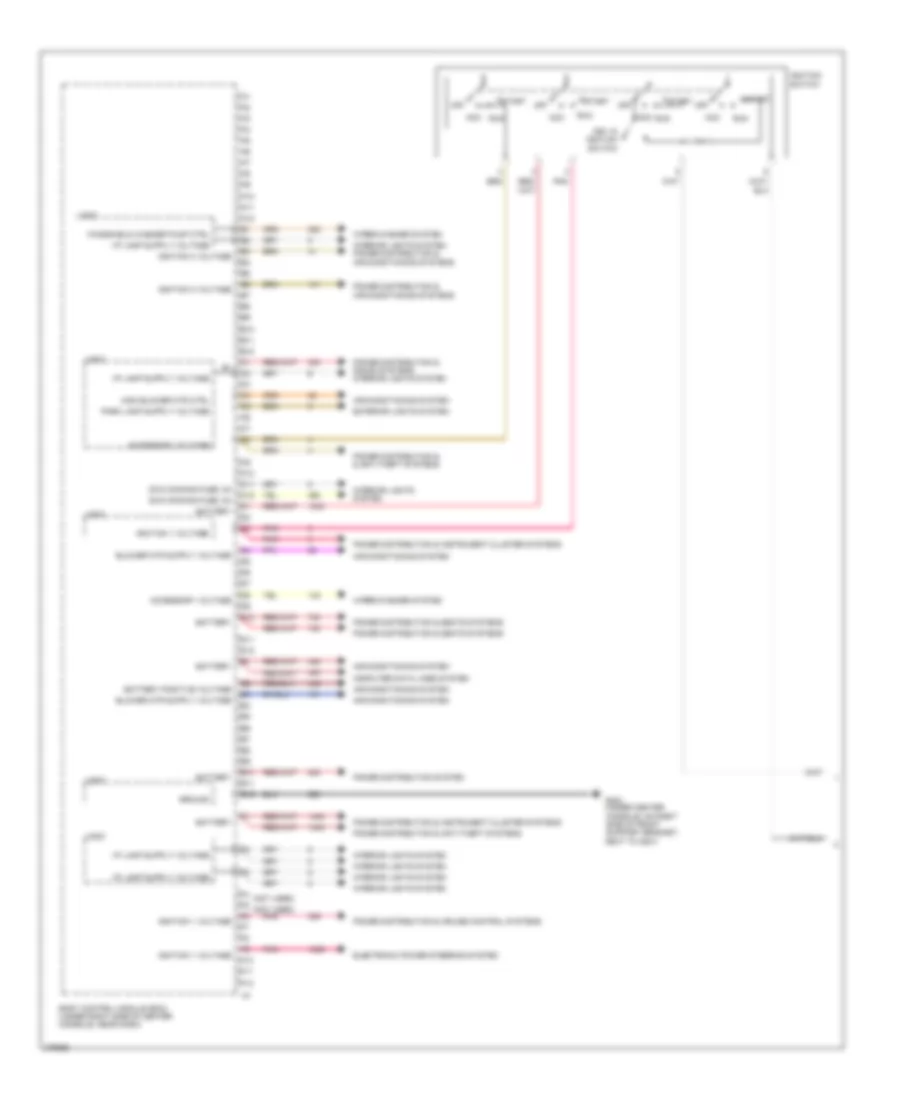
Body Control Modules Wiring Diagram (3 of 4) for Pontiac G6 2008
 https://portal-diagnostov.com/license.html
Automotive Electricians Portal FZCO
Automotive Electricians Portal FZCO
https://portal-diagnostov.com/license.html
https://portal-diagnostov.com/license.html
Automotive Electricians Portal FZCO
Automotive Electricians Portal FZCOList of elements for Body Control Modules Wiring Diagram (3 of 4) for Pontiac G6 2008:
- (not used)
- A10
- A11
- A12
- Acc
- Acc run
- Accessory voltage
- Air conditioning system
- B10
- B11
- B12
- Battery
- Battery positive voltage
- Body control module (bcm) (under right side of center console, near dash)
- C10
- C11
- C12
- Computer data lines system
- D10
- D11
- D12
- E10
- E11
- E12
- Electronic power steering system
- Exterior lights system
- F10
- F11
- F12
- G203 (under center console, on right side of front support bracket, next to g201)
- Ground
- High blower mtr ctrl
- Ignition 1 voltage
- Ignition 3 voltage
- Ignition switch
- Interior lights system
- Interior lights system power distribution & air conditioning systems
- Key in ignition switch
- Logic
- Off
- Pnk
- Power distribution & & anti-theft systems
- Power distribution & air conditioning systems
- Power distribution & anti-theft systems
- Power distribution & cruise control systems
- Power distribution & instrument cluster systems
- Power distribution & seats systems
- Power distribution & sound systems interior lights system
- Power distribution system
- Run
- Start
- Swc dimming fuse, 2a
- Windshield washer pump ctrl
- Wiper/washer system
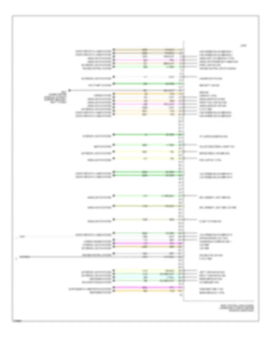
Body Control Modules Wiring Diagram (4 of 4) for Pontiac G6 2008
 https://portal-diagnostov.com/license.html
Automotive Electricians Portal FZCO
Automotive Electricians Portal FZCO
https://portal-diagnostov.com/license.html
https://portal-diagnostov.com/license.html
Automotive Electricians Portal FZCO
Automotive Electricians Portal FZCOList of elements for Body Control Modules Wiring Diagram (4 of 4) for Pontiac G6 2008:
- 5 volt ref
- A/c request sig
- Adjustable pedal inhibit sw
- Air conditioning system
- Anti-theft system
- Body control module (bcm) (under right side of center console, near dash)
- Brake pedal pos sen sig
- Computer data lines system
- Cruise control switch signal
- Cruise control system
- Cruise ctrl sw sig
- Defogger system
- Drl ambient light sen low ref
- Drl ambient light sen sig
- Exterior lights system
- Flash to pass sig
- Fog lamp rly ctrl
- Front fog lamp sw sig
- G201 (under center console, on front support bracket, next to g203)
- Ground
- Hazard switch sig
- Headlamp dimmer sw hi beam sig
- Headlamp low beam rly ctrl
- Headlamps sw off sig
- Headlamps sw on sig
- Headlights system
- High speed gmlan ser bus +
- High speed gmlan ser bus -
- Horn rly ctrl
- Horns system
- I/p lamps dimmer sw sig
- Interior lights system
- Left turn sig sw sig
- Logic
- Low ref
- Low speed gmlan ser data
- Off/run/crank volt sig
- Park lamp sw sig
- Pass seat belt ind
- Rear defog rly ctrl
- Rear defog sw sig
- Right turn sig sw sig
- Seats system
- Security ind sig
- Tan
- Windshield wiper sw sig 1
- Wiper/washer system
COMPUTER DATA LINES
Computer Data Lines Wiring Diagram for Pontiac G6 2008
 https://portal-diagnostov.com/license.html
Automotive Electricians Portal FZCO
Automotive Electricians Portal FZCO
https://portal-diagnostov.com/license.html
https://portal-diagnostov.com/license.html
Automotive Electricians Portal FZCO
Automotive Electricians Portal FZCOList of elements for Computer Data Lines Wiring Diagram for Pontiac G6 2008:
- (left side of engine compartment) engine control module (ecm)
- 2.4l
- 3.5l & 3.9l
- 3.6l
- A/t
- B10
- Body control module (bcm) (under right side of center console, near dash)
- Data link connector (dlc) (on lower left of dash)
- Digital radio receiver (w/ convertible: in rear compt, front of spare tire compt) (w/o convertible: under rear package shelf, front of speakers)
- Electronic brake control module (ebcm) (left side of engine compartment, mounted to back side of strut tower, part of brake pressure
- Except 3.6l
- Folding top control module (right side of rear compartment)
- G201 (under center console, on front support bracket, next to g203)
- G203 (under center console, on right side of front support bracket,
- Gmlan data bus +
- Gmlan data bus -
- High speed gmlan serial data bus +
- High speed gmlan serial data bus -
- Hot at all times
- Hs gmlan data bus +
- Hs gmlan data bus -
- Hvac control module (in lower center of dash, below radio)
- Hvac ctrl (batt) fuse 10a
- Inflatable restraint sensing & diagnostic module (sdm) (under center console)
- Instrument panel cluster (ipc)
- Logic
- Low speed gmlan serial data
- Ls gmlan data
- M/t
- Modulator valve (bpmv))
- Next to g201)
- Power distribution system
- Power steering control module (under left knee bolster, to left of steering column)
- Radio
- Remote control door lock receiver (rcdlr) (if equipped) (attached to rear window shelf)
- Tan
- Theft deterrent control module (left side of dash, attached to ignition key cylinder housing)
- Transmission control module (tcm) (left of engine compt, near strut tower)
- Vehicle communication interface module (vcim) (under right side of dash)
- W/ abs
- W/ convertible
- W/ digital audio
- W/ digital radio
- W/ electronic power steering
- W/ onstar
- W/o abs
- W/o convertible
- W/o digital audio
- W/o digital radio
- W/o electronic power steering
- W/o onstar
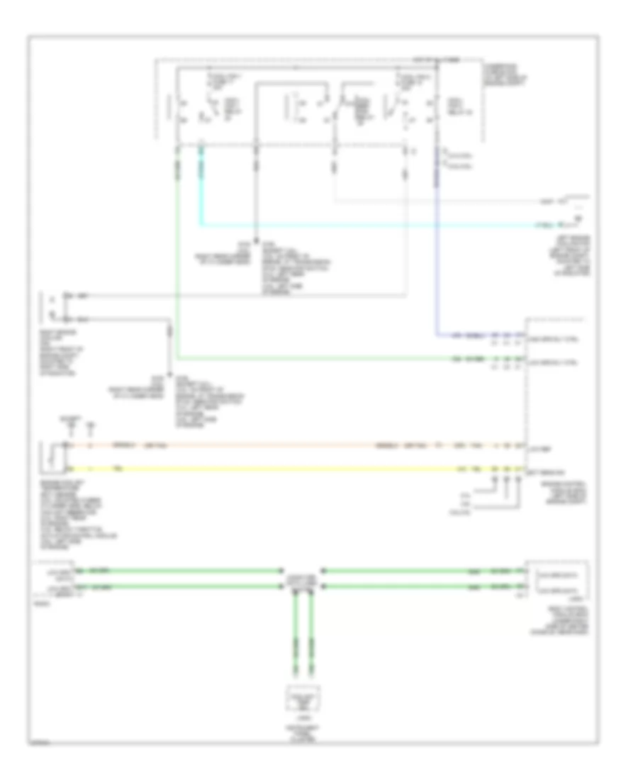
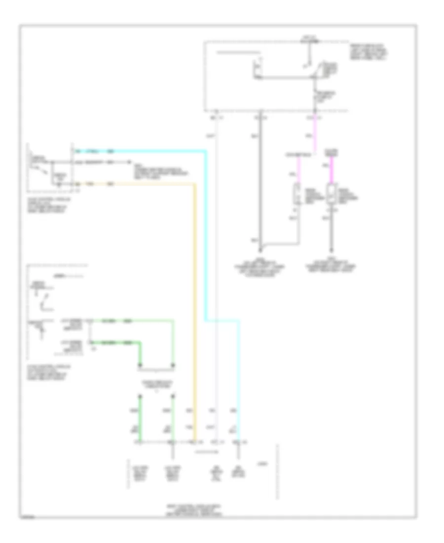
COOLING FAN
Cooling Fan Wiring Diagram for Pontiac G6 2008
 https://portal-diagnostov.com/license.html
Automotive Electricians Portal FZCO
Automotive Electricians Portal FZCO
https://portal-diagnostov.com/license.html
https://portal-diagnostov.com/license.html
Automotive Electricians Portal FZCO
Automotive Electricians Portal FZCOList of elements for Cooling Fan Wiring Diagram for Pontiac G6 2008:
- (2.4l/3.6l)
- (3.5l/3.9l)
- (or tan)
- 2.4l
- 3.5l/3.9l
- 3.6l
- 87a
- A11
- B10
- Body control module (bcm) (under right side of center console, near dash)
- Computer data lines system
- Cool fan 1 fuse 17 30a
- Cool fan 2 fuse 18 30a
- Cool ser/ par relay
- Cool/ fan 1 relay
- Cool/ fan 2 relay 30
- Coolant temp ind
- Ect sens sig
- Engine control module (ecm) (left side of engine compt)
- Engine coolant temperature (ect) sensor (3.5l: mounted in rear cylinder head, below coolant reservoir) (2.4l: right rear of engine) (3.9l: below throttle actuator control module) (3.6l: left side of engine)
- Except 3.6l
- G106 (except 3.6l) (3.5l: on front of engine, at transmission stud, near pnp switch) (2.4l: left rear of engine) (3.9l: left side of engine)
- G108 (3.6l) (right rear corner of cylinder head)
- High spd rly ctrl
- Hot at all times
- Instrument panel cluster
- Left engine cooling fan (left front of engine compt, mounted to left side of radiator)
- Logic
- Low ref
- Low spd data
- Low spd rly ctrl
- Radio
- Right engine cooling fan (right front of engine compt, mounted to right side of radiator)
- Tan
- Underhood fuse block (in left side of engine compt)
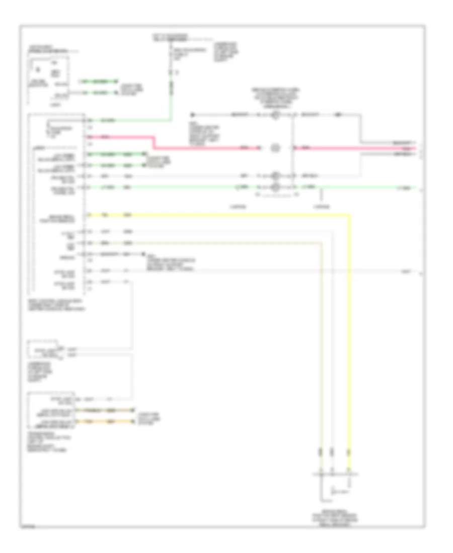
CRUISE CONTROL
2.4L VIN B
2.4L VIN B, Cruise Control Wiring Diagram (1 of 2) for Pontiac G6 2008
 https://portal-diagnostov.com/license.html
Automotive Electricians Portal FZCO
Automotive Electricians Portal FZCO
https://portal-diagnostov.com/license.html
https://portal-diagnostov.com/license.html
Automotive Electricians Portal FZCO
Automotive Electricians Portal FZCOList of elements for 2.4L VIN B, Cruise Control Wiring Diagram (1 of 2) for Pontiac G6 2008:
- (behind steering wheel, in steering column) inflatable restraint steering wheel module coil
- (ecm/ pcm)
- (in right side of brake pedal bracket)
- 3 spoke
- 5 volt ref
- Body control module (bcm) (under right side of center console, near dash)
- Brake pedal position (bpp) sensor
- Brake pedal position sens sig
- Computer data lines system
- Cruise ctrl cancel sig
- Cruise ctrl sw sig
- Cruise indicator
- G201 (under center console, on front support bracket, next to g203)
- Gmlan
- Ground
- High spd gmlan serial data bus +
- High spd gmlan serial data bus -
- Hot w/ run/crank relay energized
- Ibcm (run/crank) fuse 21 30a
- Ign
- Instrument panel cluster (ipc)
- J201
- Logic
- Low ref
- Low speed gmlan serial data
- Pnk
- Run/crank fuse 2a
- Stop lamp sw sig
- Tan
- Transmission control module (tcm) (left of engine compt, near strut tower)
- Underhood fuse block (in left side of engine compt)
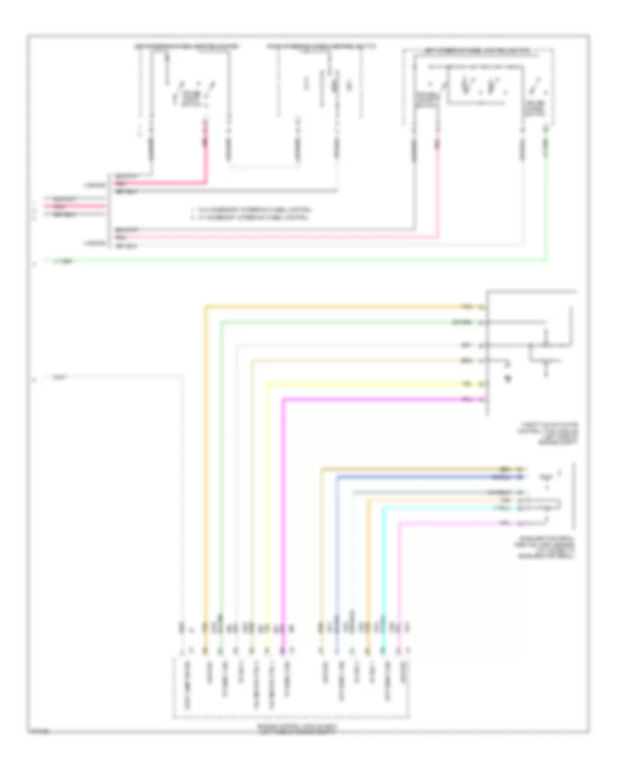
2.4L VIN B, Cruise Control Wiring Diagram (2 of 2) for Pontiac G6 2008
 https://portal-diagnostov.com/license.html
Automotive Electricians Portal FZCO
Automotive Electricians Portal FZCO
https://portal-diagnostov.com/license.html
https://portal-diagnostov.com/license.html
Automotive Electricians Portal FZCO
Automotive Electricians Portal FZCOList of elements for 2.4L VIN B, Cruise Control Wiring Diagram (2 of 2) for Pontiac G6 2008:
- 3 spoke
- 4 spoke
- 5v ref 1
- 5v ref 2
- Accelerator pedal position (app) sensor (attached to accelerator pedal)
- App sens 1 sig
- App sens 2 sig
- Cruise cancel switch
- Cruise on/off switch
- Engine control module (ecm) (left side of engine compt)
- Left steering wheel control switch
- Low ref
- Pnk
- Res +
- Right steering wheel control switch
- Set -
- Stop lamp sw sig
- Tac motor ctrl 1
- Tac motor ctrl 2
- Tan
- Throttle actuator control (tac) module (left side of engine compt)
- Tp sens 1 sig
- Tp sens 2 sig
- W/ accessory steering wheel control
- W/o accessory steering wheel control
3.5L VIN N
3.5L VIN N, Cruise Control Wiring Diagram (1 of 2) for Pontiac G6 2008
 https://portal-diagnostov.com/license.html
Automotive Electricians Portal FZCO
Automotive Electricians Portal FZCO
https://portal-diagnostov.com/license.html
https://portal-diagnostov.com/license.html
Automotive Electricians Portal FZCO
Automotive Electricians Portal FZCOList of elements for 3.5L VIN N, Cruise Control Wiring Diagram (1 of 2) for Pontiac G6 2008:
- (behind steering wheel, in steering column) inflatable restraint steering wheel module coil
- (ecm/ pcm)
- (in right side of brake pedal bracket) brake pedal position sensor
- 3 spoke
- 3.6l
- 3.9l
- 5 volt ref
- Body control module (bcm) (under right side of center console, near dash)
- Brake pedal position sens sig
- Computer data lines system
- Cruise ctrl cancel sig
- Cruise ctrl sw sig
- Cruise indicator
- Except 3.6l
- G201 (under center console, on front support bracket, next to g203)
- Gmlan
- Ground
- High spd gmlan serial data bus +
- High spd gmlan serial data bus -
- Hot w/ run/crank relay energized
- Ibcm (run/crank) fuse 21 30a
- Ign
- Instrument panel cluster (ipc)
- J201
- Logic
- Low ref
- Low speed gmlan serial data
- Pnk
- Run/crank fuse 2a
- Stop lamp sw sig
- Tan
- Transmission control module (tcm) (left of engine compt, near strut tower)
- Underhood fuse block (in left side of engine compt)
- Vehicle speed sensor (vss) (right side of transmission, near right axle shaft)
- Vss high sig
- Vss low sig
3.5L VIN N, Cruise Control Wiring Diagram (2 of 2) for Pontiac G6 2008
 https://portal-diagnostov.com/license.html
Automotive Electricians Portal FZCO
Automotive Electricians Portal FZCO
https://portal-diagnostov.com/license.html
https://portal-diagnostov.com/license.html
Automotive Electricians Portal FZCO
Automotive Electricians Portal FZCOList of elements for 3.5L VIN N, Cruise Control Wiring Diagram (2 of 2) for Pontiac G6 2008:
- 3 spoke
- 3.5l/3.9l
- 3.6l
- 4 spoke
- 5v ref 1
- 5v ref 2
- Accelerator pedal position (app) sensor (attached to accelerator pedal)
- App sens 1 sig
- App sens 2 sig
- Cruise cancel switch
- Cruise on/off switch
- Engine control module (ecm) (left side of engine compt)
- Left steering wheel control switch
- Low ref
- Pnk
- Res +
- Right steering wheel control switch
- Set -
- Stop lamp sw sig
- Tac motor ctrl-1
- Tac motor ctrl-2
- Tan
- Throttle actuator control (tac) module (3.5l: top left rear of engine compt, on throttle assembly) (3.6l: left rear side of engine compt, on throttle body assembly) (3.9l: top left rear of engine)
- Tp sens 1 sig
- Tp sens 2 sig
- W/ accessory steering wheel control
- W/o accessory steering wheel control
3.6L VIN 7
3.6L VIN 7, Cruise Control Wiring Diagram (1 of 2) for Pontiac G6 2008
 https://portal-diagnostov.com/license.html
Automotive Electricians Portal FZCO
Automotive Electricians Portal FZCO
https://portal-diagnostov.com/license.html
https://portal-diagnostov.com/license.html
Automotive Electricians Portal FZCO
Automotive Electricians Portal FZCOList of elements for 3.6L VIN 7, Cruise Control Wiring Diagram (1 of 2) for Pontiac G6 2008:
- (behind steering wheel, in steering column) inflatable restraint steering wheel module coil
- (ecm/ pcm)
- (in right side of brake pedal bracket) brake pedal position sensor
- 3 spoke
- 3.6l
- 3.9l
- 5 volt ref
- Body control module (bcm) (under right side of center console, near dash)
- Brake pedal position sens sig
- Computer data lines system
- Cruise ctrl cancel sig
- Cruise ctrl sw sig
- Cruise indicator
- Except 3.6l
- G201 (under center console, on front support bracket, next to g203)
- Gmlan
- Ground
- High spd gmlan serial data bus +
- High spd gmlan serial data bus -
- Hot w/ run/crank relay energized
- Ibcm (run/crank) fuse 21 30a
- Ign
- Instrument panel cluster (ipc)
- J201
- Logic
- Low ref
- Low speed gmlan serial data
- Pnk
- Run/crank fuse 2a
- Stop lamp sw sig
- Tan
- Transmission control module (tcm) (left of engine compt, near strut tower)
- Underhood fuse block (in left side of engine compt)
- Vehicle speed sensor (vss) (right side of transmission, near right axle shaft)
- Vss high sig
- Vss low sig
3.6L VIN 7, Cruise Control Wiring Diagram (2 of 2) for Pontiac G6 2008
 https://portal-diagnostov.com/license.html
Automotive Electricians Portal FZCO
Automotive Electricians Portal FZCO
https://portal-diagnostov.com/license.html
https://portal-diagnostov.com/license.html
Automotive Electricians Portal FZCO
Automotive Electricians Portal FZCOList of elements for 3.6L VIN 7, Cruise Control Wiring Diagram (2 of 2) for Pontiac G6 2008:
- 3 spoke
- 3.5l/3.9l
- 3.6l
- 4 spoke
- 5v ref 1
- 5v ref 2
- Accelerator pedal position (app) sensor (attached to accelerator pedal)
- App sens 1 sig
- App sens 2 sig
- Cruise cancel switch
- Cruise on/off switch
- Engine control module (ecm) (left side of engine compt)
- Left steering wheel control switch
- Low ref
- Pnk
- Res +
- Right steering wheel control switch
- Set -
- Stop lamp sw sig
- Tac motor ctrl-1
- Tac motor ctrl-2
- Tan
- Throttle actuator control (tac) module (3.5l: top left rear of engine compt, on throttle assembly) (3.6l: left rear side of engine compt, on throttle body assembly) (3.9l: top left rear of engine)
- Tp sens 1 sig
- Tp sens 2 sig
- W/ accessory steering wheel control
- W/o accessory steering wheel control
3.9L VIN 1
3.9L VIN 1, Cruise Control Wiring Diagram (1 of 2) for Pontiac G6 2008
 https://portal-diagnostov.com/license.html
Automotive Electricians Portal FZCO
Automotive Electricians Portal FZCO
https://portal-diagnostov.com/license.html
https://portal-diagnostov.com/license.html
Automotive Electricians Portal FZCO
Automotive Electricians Portal FZCOList of elements for 3.9L VIN 1, Cruise Control Wiring Diagram (1 of 2) for Pontiac G6 2008:
- (behind steering wheel, in steering column) inflatable restraint steering wheel module coil
- (ecm/ pcm)
- (in right side of brake pedal bracket) brake pedal position sensor
- 3 spoke
- 3.6l
- 3.9l
- 5 volt ref
- Body control module (bcm) (under right side of center console, near dash)
- Brake pedal position sens sig
- Computer data lines system
- Cruise ctrl cancel sig
- Cruise ctrl sw sig
- Cruise indicator
- Except 3.6l
- G201 (under center console, on front support bracket, next to g203)
- Gmlan
- Ground
- High spd gmlan serial data bus +
- High spd gmlan serial data bus -
- Hot w/ run/crank relay energized
- Ibcm (run/crank) fuse 21 30a
- Ign
- Instrument panel cluster (ipc)
- J201
- Logic
- Low ref
- Low speed gmlan serial data
- Pnk
- Run/crank fuse 2a
- Stop lamp sw sig
- Tan
- Transmission control module (tcm) (left of engine compt, near strut tower)
- Underhood fuse block (in left side of engine compt)
- Vehicle speed sensor (vss) (right side of transmission, near right axle shaft)
- Vss high sig
- Vss low sig
3.9L VIN 1, Cruise Control Wiring Diagram (2 of 2) for Pontiac G6 2008
 https://portal-diagnostov.com/license.html
Automotive Electricians Portal FZCO
Automotive Electricians Portal FZCO
https://portal-diagnostov.com/license.html
https://portal-diagnostov.com/license.html
Automotive Electricians Portal FZCO
Automotive Electricians Portal FZCOList of elements for 3.9L VIN 1, Cruise Control Wiring Diagram (2 of 2) for Pontiac G6 2008:
- 3 spoke
- 3.5l/3.9l
- 3.6l
- 4 spoke
- 5v ref 1
- 5v ref 2
- Accelerator pedal position (app) sensor (attached to accelerator pedal)
- App sens 1 sig
- App sens 2 sig
- Cruise cancel switch
- Cruise on/off switch
- Engine control module (ecm) (left side of engine compt)
- Left steering wheel control switch
- Low ref
- Pnk
- Res +
- Right steering wheel control switch
- Set -
- Stop lamp sw sig
- Tac motor ctrl-1
- Tac motor ctrl-2
- Tan
- Throttle actuator control (tac) module (3.5l: top left rear of engine compt, on throttle assembly) (3.6l: left rear side of engine compt, on throttle body assembly) (3.9l: top left rear of engine)
- Tp sens 1 sig
- Tp sens 2 sig
- W/ accessory steering wheel control
- W/o accessory steering wheel control
DEFOGGERS
Defoggers Wiring Diagram for Pontiac G6 2008
 https://portal-diagnostov.com/license.html
Automotive Electricians Portal FZCO
Automotive Electricians Portal FZCO
https://portal-diagnostov.com/license.html
https://portal-diagnostov.com/license.html
Automotive Electricians Portal FZCO
Automotive Electricians Portal FZCOList of elements for Defoggers Wiring Diagram for Pontiac G6 2008:
- A12
- B8 x1
- Body control module (bcm) (under right side of center console, near dash)
- Computer data lines system
- Convertible
- Coupe/ sedan
- Defog ind
- Defog switch
- F2 x4
- G201 (under center console, on front support bracket, next to g203)
- G301 (on right rear of passenger compt, under right rear seat back)
- G302 (on left rear of passenger compt, under left rear seat back, towards door)
- Hot at all times
- Hvac control module (automatic a/c) (in lower center of dash, below radio)
- Hvac control module (manual a/c) (in lower center of dash, below radio)
- Logic
- Low spd gmlan serial data
- Low speed gmlan ser data
- R/wdo defog relay
- Rear fuse block (left side of rear compt, behind left rear wheel well)
- Rear window defogger grid
- Rr defog fuse 23 30a
- Rr defog rly ctrl
- Rr defog sw sig
- Tan
- X1 c12
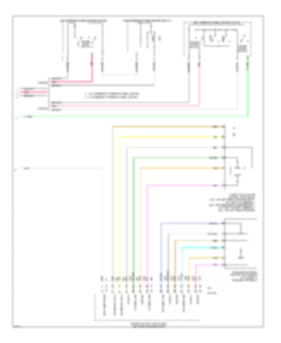
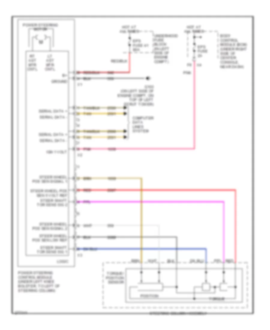
ELECTRONIC POWER STEERING
Electronic Power Steering Wiring Diagram for Pontiac G6 2008
 https://portal-diagnostov.com/license.html
Automotive Electricians Portal FZCO
Automotive Electricians Portal FZCO
https://portal-diagnostov.com/license.html
https://portal-diagnostov.com/license.html
Automotive Electricians Portal FZCO
Automotive Electricians Portal FZCOList of elements for Electronic Power Steering Wiring Diagram for Pontiac G6 2008:
- Body control module (bcm) (under right side of center console, near dash)
- Computer data lines system
- Eps fuse 2a
- Eps fuse 41 80a
- G103 (on left side of engine compt, on top of left strut tower)
- Ground
- Hot at all times
- Ign 1 volt
- Logic
- Lt ast mtr cntl
- Pnk
- Position
- Power steering control module (under left knee bolster, to left of steering column)
- Power steering motor
- Red
- Rt ast mtr cntl
- Serial data +
- Serial data -
- Steer shaft tor sens sig 1
- Steer shaft tor sens sig 2
- Steer wheel pos sen 5 volt ref
- Steer wheel pos sen low ref
- Steer wheel pos sen signal 1
- Steer wheel pos sen signal 2
- Steering column assembly
- Tan
- Torque
- Torque/ position sensor
- Underhood fuse block (in left side of engine compt)
ENGINE PERFORMANCE
2.4L VIN B
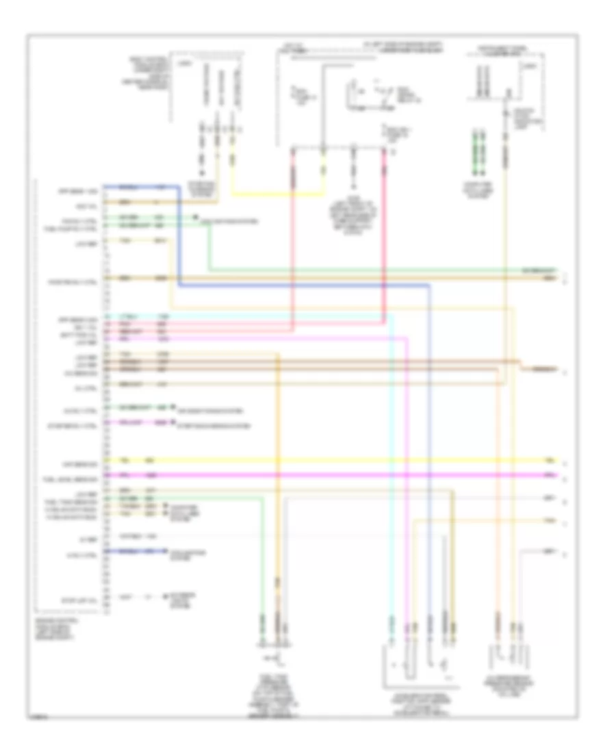
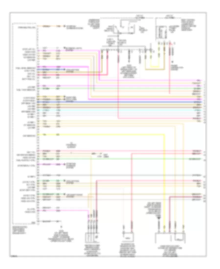
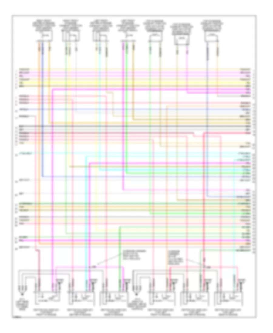
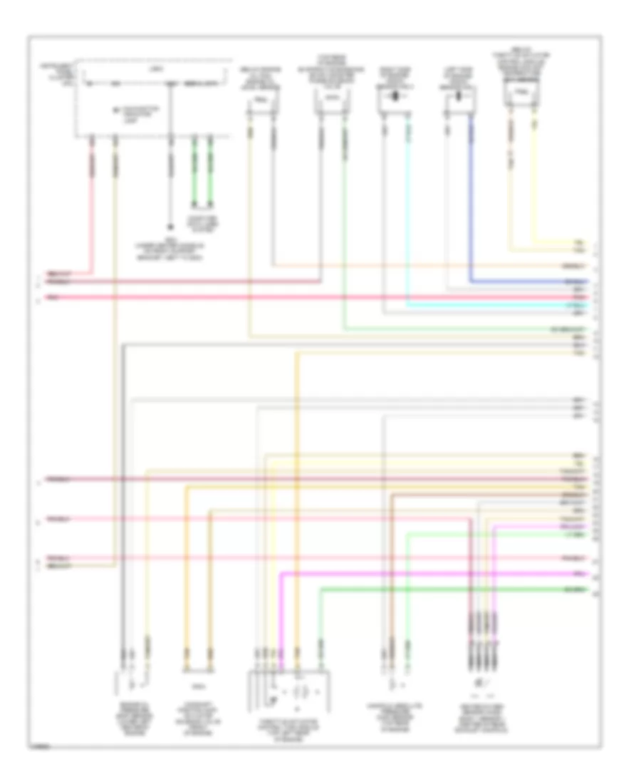
2.4L VIN B, Engine Performance Wiring Diagram (1 of 4) for Pontiac G6 2008
 https://portal-diagnostov.com/license.html
Automotive Electricians Portal FZCO
Automotive Electricians Portal FZCO
https://portal-diagnostov.com/license.html
https://portal-diagnostov.com/license.html
Automotive Electricians Portal FZCO
Automotive Electricians Portal FZCOList of elements for 2.4L VIN B, Engine Performance Wiring Diagram (1 of 4) for Pontiac G6 2008:
- (in left side of engine compt) underhood fuse block
- 5v ref
- A/c refrigerant pressure sensor (mounted on a/c line)
- A/c rly ctrl
- A/c sens sig
- Acc vol
- Acc voltage
- Accelerator pedal position (app) sensor (attached to accelerator pedal)
- Air conditioning system
- App sens 1 sig
- App sens 2 sig
- Batt pos vol
- Body control module (bcm) (under right side of center console, near dash)
- C10
- Computer data lines system
- Cooling fans system
- Crank voltage
- Ecm fuse 13 10a
- Ecm ign 1 fuse 16 10a
- Engine control module (ecm) (left side of engine compt)
- Exterior lights system
- Fan rly ctrl
- Fuel level sens sig
- Fuel pump rly ctrl
- Fuel tank pressure (ftp) sensor (on top of fuel pump & sender assembly, part of fuel pump & sender assembly)
- Fuel tank sens sig
- G109 (left front of engine compt, on left rear side of core support, between g101 & g104)
- Gmlan data
- Hi gmlan data bus+
- Hi gmlan data bus-
- Hi rly ctrl
- Hot at all times
- Ign
- Ign 1 vol
- Instrument panel cluster (ipc)
- Logic
- Low ref
- Maf sens sig
- Malfun- ction indicator lamp
- Mil ctrl
- Pnk
- Pwr/trn rly ctrl
- Rly coil ctrl
- Run/ crank relay 32
- Starter rly ctrl
- Starting/ charging system
- Starting/charging system
- Stop lmp vol
- Tan
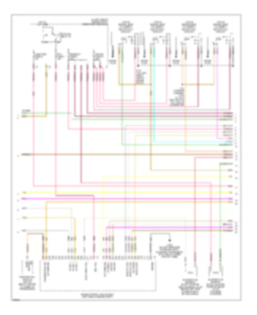
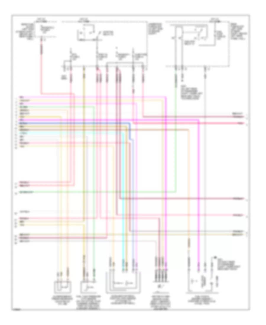
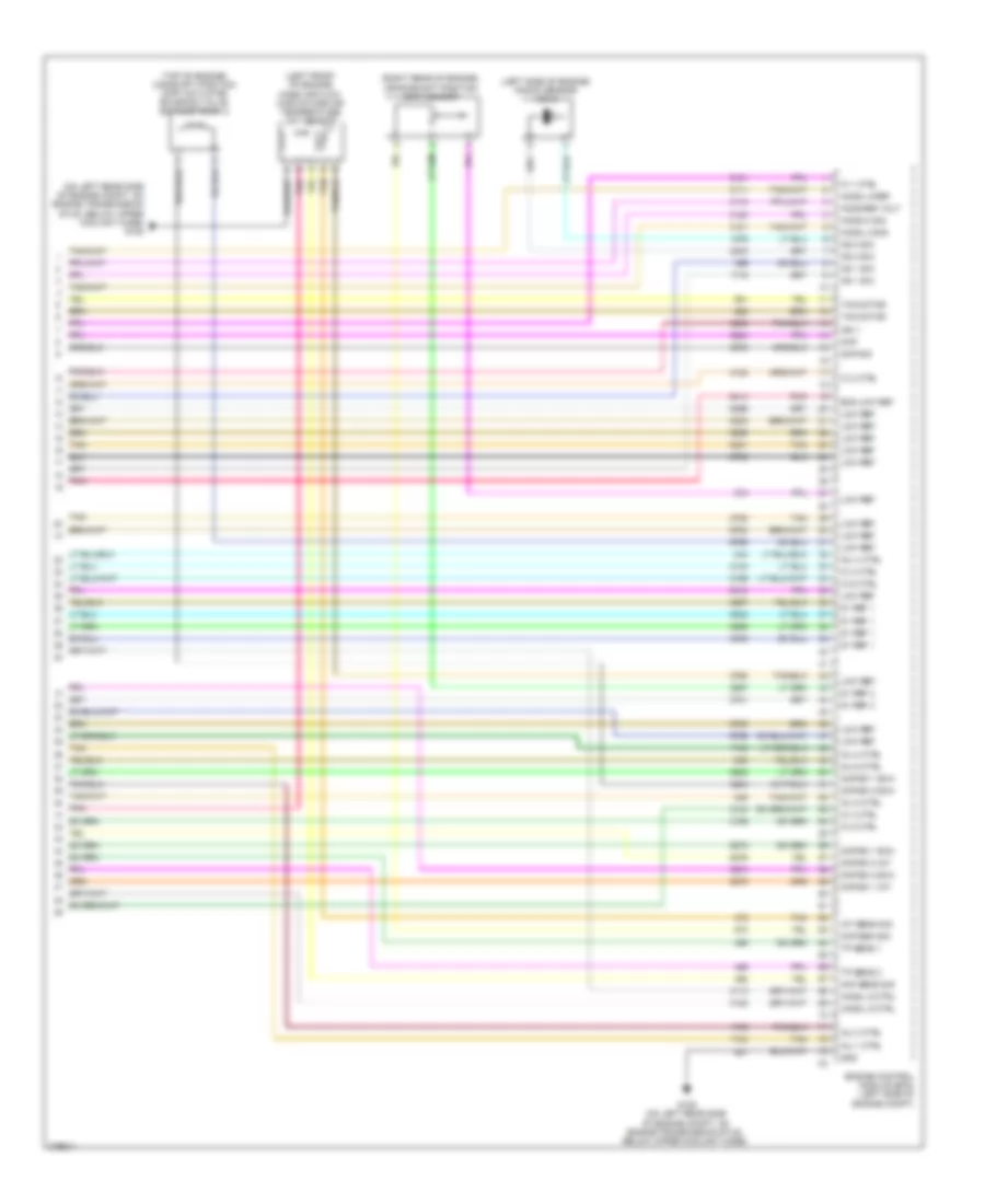
2.4L VIN B, Engine Performance Wiring Diagram (2 of 4) for Pontiac G6 2008
 https://portal-diagnostov.com/license.html
Automotive Electricians Portal FZCO
Automotive Electricians Portal FZCO
https://portal-diagnostov.com/license.html
https://portal-diagnostov.com/license.html
Automotive Electricians Portal FZCO
Automotive Electricians Portal FZCOList of elements for 2.4L VIN B, Engine Performance Wiring Diagram (2 of 4) for Pontiac G6 2008:
- (in left side of engine compt) underhood fuse block
- (top of engine, near cylinder 1) ignition coil/ module 1
- (top of engine, near cylinder 2) ignition coil/ module 2
- (top of engine, near cylinder 3) ignition coil/ module 3
- (top of engine, near cylinder 4) ignition coil/ module 4
- 5v ref 1
- A10
- B11
- C11
- D11
- E11
- Ect sens sig
- Emission 1 fuse 6 10a
- Engine control module (ecm) (left side of engine compt)
- Etc fuse 2 15a
- Evap vent ctrl
- Evaporative emission (evap) canister purge solenoid valve (top rear of engine)
- Evaporative emission (evap) canister vent solenoid valve (behind left side of rear fascia splash shield)
- G105 (on left rear side of engine compt, on engine transmission stud, below upper coolant hose)
- G110 (top left front side of engine block)
- Ground
- Ho2s lo ctrl
- Ho2s lo ref
- Hot at all times
- Iat sens sig
- Ign 1 vol
- Ign mod fuse 43 15a
- Injectors fuse 44 10a
- J101 (in engine harness, 13 cm (5.118 in) from ignition coil/ module 4 connector)
- Low ref
- Nca
- Oil press
- Park/neutral position switch (below master cylinder, on transmission)
- Park/neutral sig
- Pnk
- Pwr/trn relay 33
- Sig neutral park/
- Spark plug
- Tan
- Tp sens 2
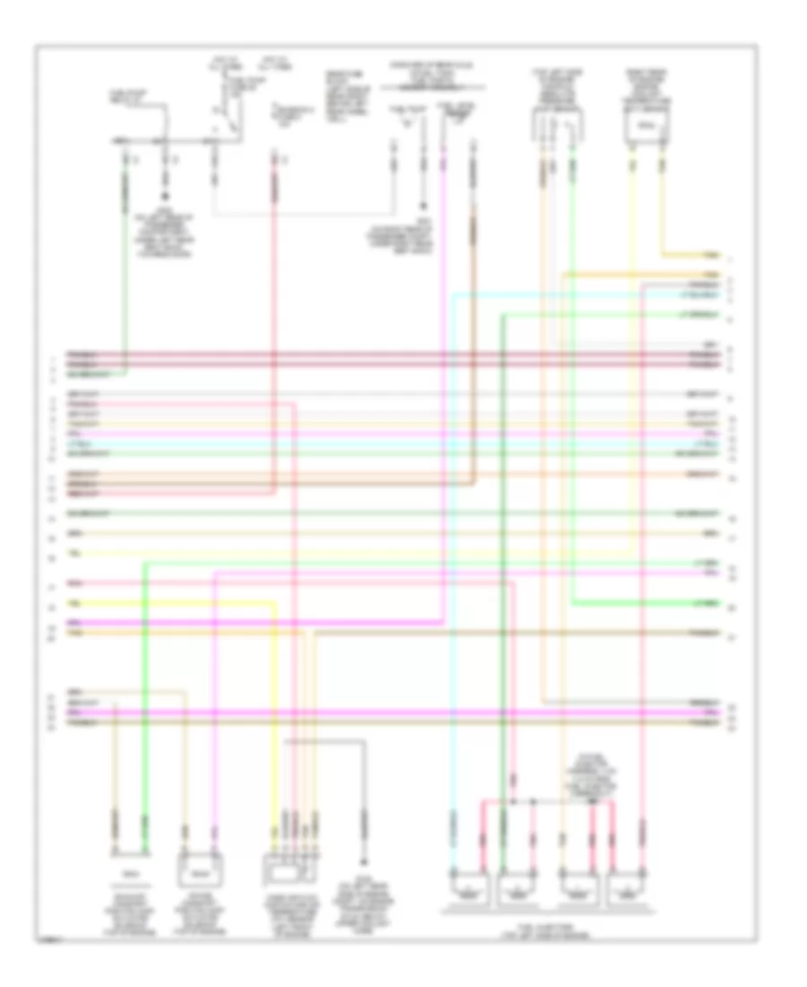
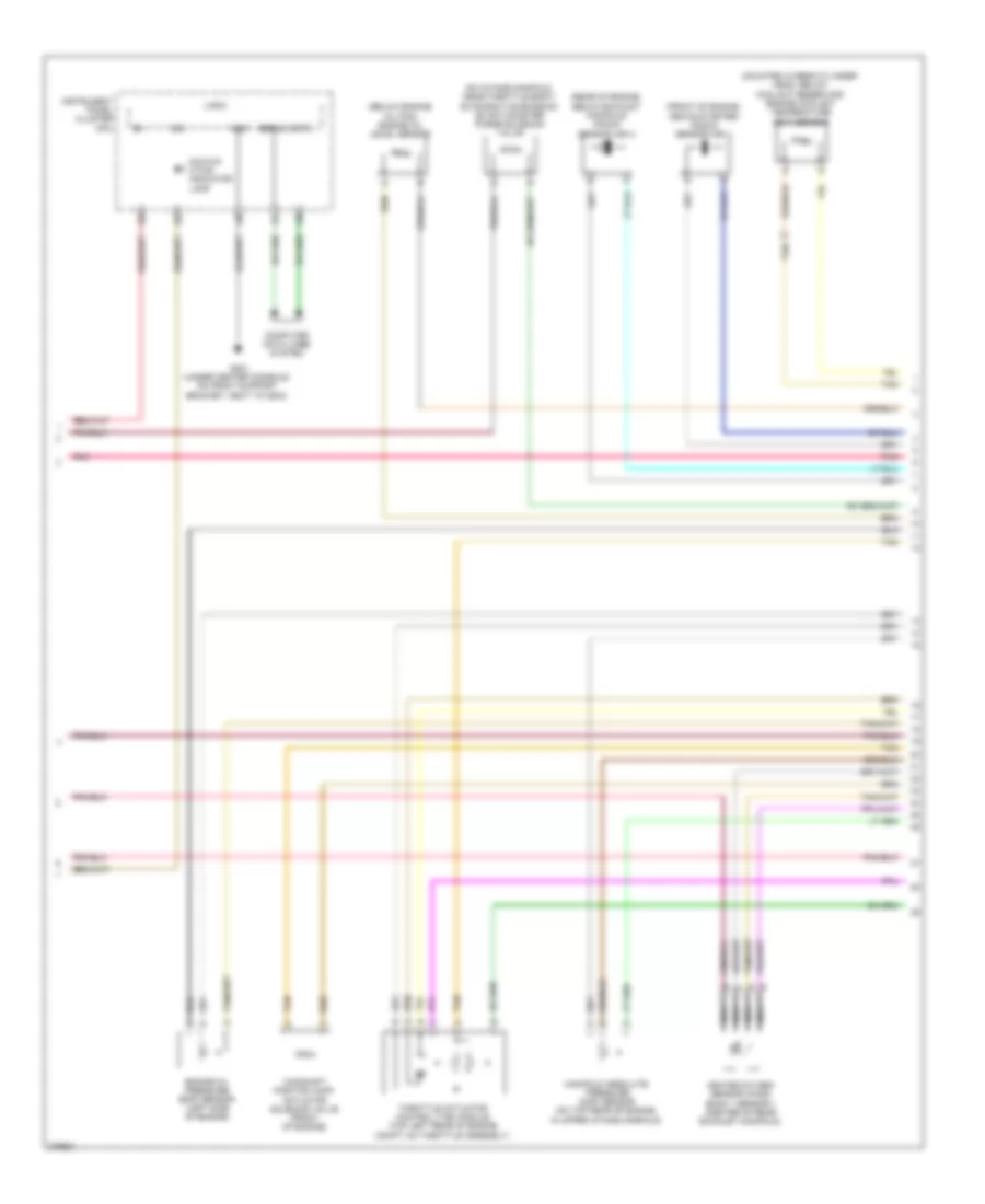
2.4L VIN B, Engine Performance Wiring Diagram (3 of 4) for Pontiac G6 2008
 https://portal-diagnostov.com/license.html
Automotive Electricians Portal FZCO
Automotive Electricians Portal FZCO
https://portal-diagnostov.com/license.html
https://portal-diagnostov.com/license.html
Automotive Electricians Portal FZCO
Automotive Electricians Portal FZCOList of elements for 2.4L VIN B, Engine Performance Wiring Diagram (3 of 4) for Pontiac G6 2008:
- (forward of rear axle, in fuel tank) fuel pump & sender assembly
- (in fuel injector harness, 4 cm (1.6 in) from fuel injector 2 breakout) j130
- (right rear of engine) engine coolant temperature (ect) sensor
- (top left side of engine) manifold absolute pressure (map) sensor
- A10
- Emission 2 fuse 5 10a
- Exhaust camshaft position (cmp) actuator solenoid (top of engine)
- Fuel injectors (top left side of engine)
- Fuel level sensor
- Fuel pump
- Fuel pump fuse 25 15a
- Fuel/pump relay 37
- G105 (on left rear side of engine compt, on engine transmission stud, below upper coolant hose)
- G301 (on right rear of passenger compt, under right rear seat back)
- G302 (on left rear of passenger compartment, under left rear seat back, towards door)
- Hot at all times
- Intake camshaft position (cmp) actuator solenoid (top of engine)
- Mass air flow (maf)/intake air temperature (iat) sensor (left front of engine)
- Pnk
- Rear fuse block (left side of rear compt, behind left rear wheel well)
- Tan
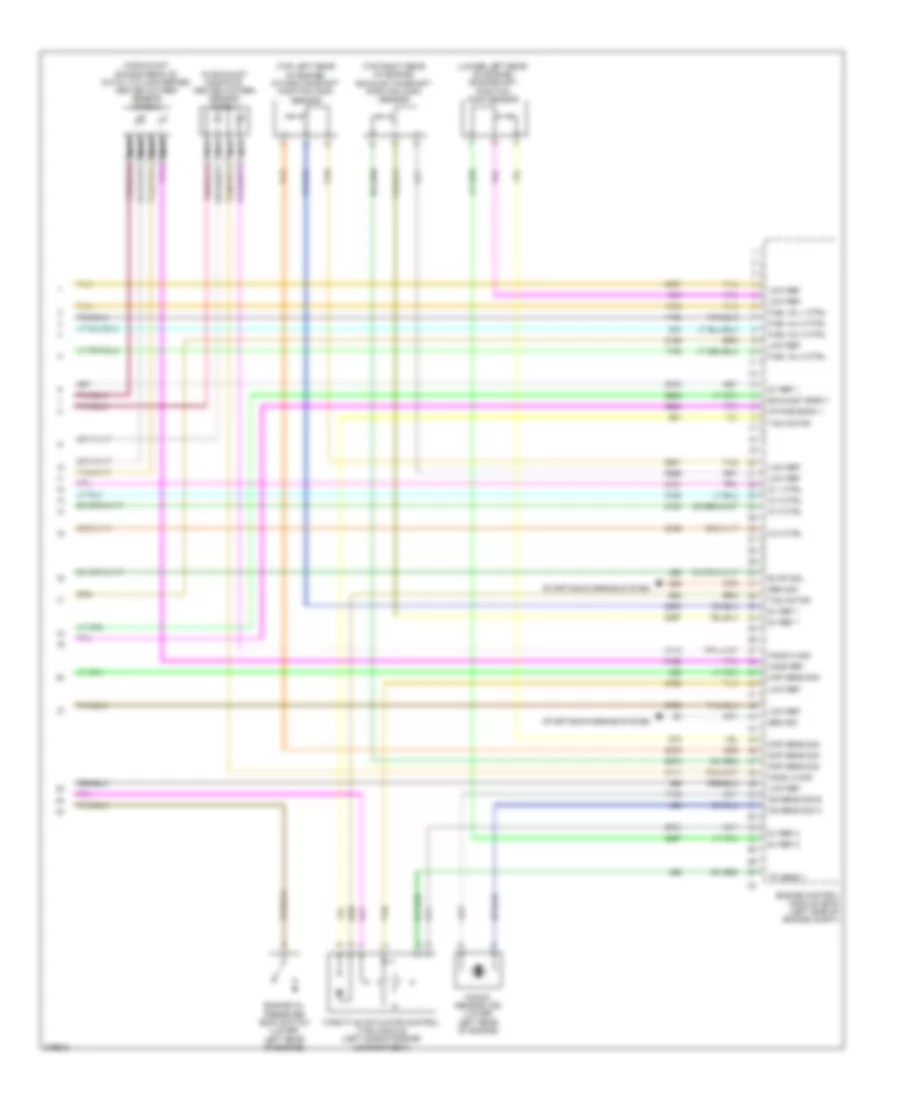
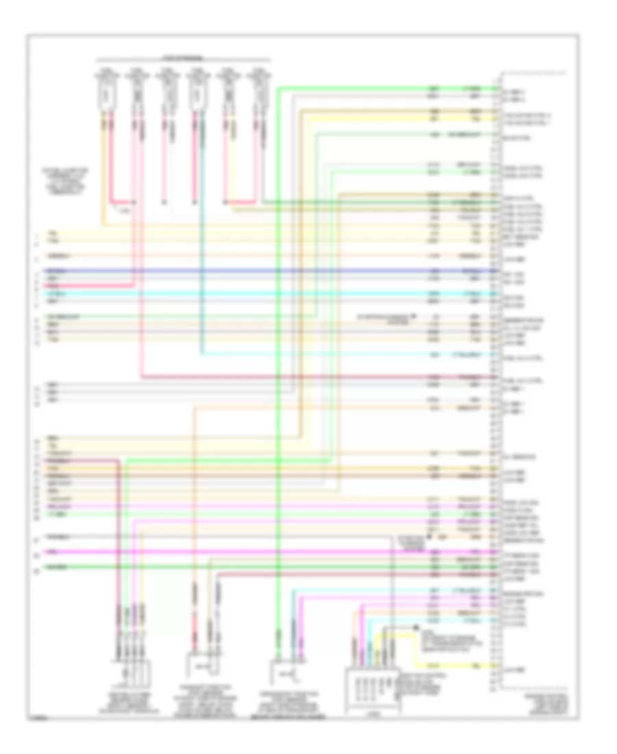
2.4L VIN B, Engine Performance Wiring Diagram (4 of 4) for Pontiac G6 2008
 https://portal-diagnostov.com/license.html
Automotive Electricians Portal FZCO
Automotive Electricians Portal FZCO
https://portal-diagnostov.com/license.html
https://portal-diagnostov.com/license.html
Automotive Electricians Portal FZCO
Automotive Electricians Portal FZCOList of elements for 2.4L VIN B, Engine Performance Wiring Diagram (4 of 4) for Pontiac G6 2008:
- (in exhaust manifold) heated oxygen sensor (ho2s) 1
- (in exhaust, downstream of catalytic converter) heated oxygen sensor (ho2s) 2
- (lower left rear of engine) crankshaft position (ckp) sensor
- (top left rear of engine) intake camshaft position (cmp) sensor
- (top right rear of engine) exhaust camshaft position (cmp) sensor
- 5v ref 1
- 5v ref 2
- Ckp sens sig
- Cmp sens sig
- Engine control module (ecm) (left side of engine compt)
- Engine oil pressure (eop) switch (lower left rear of engine)
- Evap sol
- Exhaust bank 1
- Fuel inj 1 ctrl
- Fuel inj 2 ctrl
- Fuel inj 3 ctrl
- Fuel inj 4 ctrl
- Gen sig
- Ho2s hi sig
- Ho2s lo sig
- Ho2s ref
- Ic 1 ctrl
- Ic 2 ctrl
- Ic 3 ctrl
- Ic 4 ctrl
- Intake bank 1
- Knock sensor (ks) (lower left rear of engine)
- Ks sens sig a
- Ks sens sig b
- Low ref
- Map sens sig
- Nca
- Starting/charging system
- Tac motor
- Tan
- Throttle actuator control (tac) module (left side of engine compartment)
- Tp sens 1
3.5L VIN N
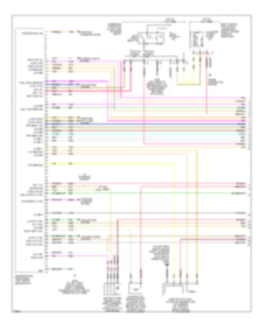
3.5L VIN N, Engine Performance Wiring Diagram (1 of 4) for Pontiac G6 2008
 https://portal-diagnostov.com/license.html
Automotive Electricians Portal FZCO
Automotive Electricians Portal FZCO
https://portal-diagnostov.com/license.html
https://portal-diagnostov.com/license.html
Automotive Electricians Portal FZCO
Automotive Electricians Portal FZCOList of elements for 3.5L VIN N, Engine Performance Wiring Diagram (1 of 4) for Pontiac G6 2008:
- (not used)
- (on left rear side of engine compt, on engine transmission stud, below upper coolant hose) g105
- 5v ref 1
- 5v ref 2
- A/c rly ctrl
- A/c sens sig
- Acc vol
- Air conditioning system
- App sens 1 sig
- App sens 2 sig
- Batt pos vol
- Body control module (bcm) (under right side of center console, near dash)
- C10
- Cluster/ theft fuse 10a
- Computer data lines system
- Cooling fans system
- Ecm fuse 51 10a
- Engine control module (ecm) (left side of engine compt)
- Evap vent ctrl
- Evaporative emission (evap) canister vent solenoid valve (behind left side of rear fascia splash shield)
- Exterior lights system
- Fuel level sens sig
- Fuel pump rly ctrl
- Fuel tank sens sig
- G105 (on left rear side of engine compt, on engine transmission stud, below upper coolant hose)
- G109 (left front of engine compt, on left rear side of core support, between g101 & g104)
- Gnd
- Heated oxygen sensor (ho2s) bank 2 sensor 2 (in exhaust, after catalytic converter)
- Hi data bus+
- Hi data bus-
- Hi rly ctrl
- Ho2s hi sig
- Ho2s low ctrl
- Ho2s low sig
- Hot at all times
- Iat sens sig
- Ign 1 vol
- Ign 1/ ecm ign fuse 3 15a
- Ign mod fuse 43 15a
- Logic
- Low ref
- Low rly ctrl
- Maf sens sig
- Mass air flow (maf)/ intake air temperature (iat) sensor (on top left side of engine, at air cleaner)
- Mil ctrl
- Nca
- Park/neutral sig
- Pnk
- Power distribution system
- Rly ctrl
- Run/ crank relay 32
- Run/crank rly ctrl
- Starter rly ctrl
- Starting/ charging system
- Stop lmp vol
- Tan
- Underhood fuse block (in left side of engine compt)
- Veh spd sig (sedan)
- W/ panoramic sunroof
- X108
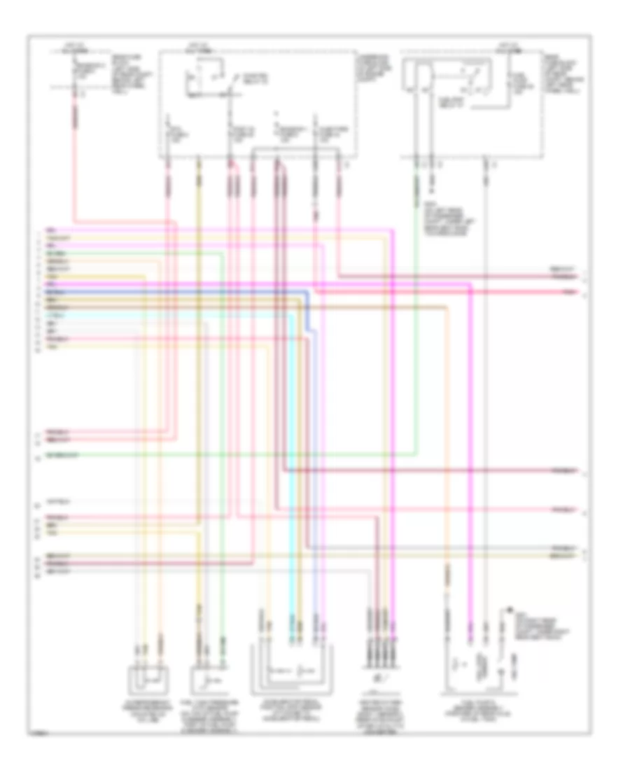
3.5L VIN N, Engine Performance Wiring Diagram (2 of 4) for Pontiac G6 2008
 https://portal-diagnostov.com/license.html
Automotive Electricians Portal FZCO
Automotive Electricians Portal FZCO
https://portal-diagnostov.com/license.html
https://portal-diagnostov.com/license.html
Automotive Electricians Portal FZCO
Automotive Electricians Portal FZCOList of elements for 3.5L VIN N, Engine Performance Wiring Diagram (2 of 4) for Pontiac G6 2008:
- (not used)
- A/c refrigerant pressure sensor (mounted on a/c line)
- A10
- Accelerator pedal position (app) sensor (attached to accelerator pedal)
- B11
- C11
- D11
- D12
- Emission 1 fuse 6 10a
- Emission 2 fuse 5 10a
- Etc fuse 2 15a
- Fuel pump
- Fuel pump & sender assembly (forward of rear axle, in fuel tank)
- Fuel pump fuse 25 15a
- Fuel tank pressure (ftp) sensor (on top of fuel pump & sender assembly, part of fuel pump & sender assembly)
- Fuel/pmp relay 37
- G301 (on right rear of passenger compt, under right rear seat back)
- G302 (on left rear of passenger compt, under left rear seat back, towards door)
- Heated oxygen sensor (ho2s) bank 1 sensor 2 (rear of exhaust, after catalytic converter)
- Hot at all times
- Injectors fuse 44 10a
- Nca
- Pnk
- Post 02 fuse 45 10a
- Pwr/trn relay 33
- Rear fuse block (left side of rear compt, behind left rear wheel well)
- Sensor fuel level
- Tan
- Underhood fuse block (in left side of engine compt)
3.5L VIN N, Engine Performance Wiring Diagram (3 of 4) for Pontiac G6 2008
 https://portal-diagnostov.com/license.html
Automotive Electricians Portal FZCO
Automotive Electricians Portal FZCO
https://portal-diagnostov.com/license.html
https://portal-diagnostov.com/license.html
Automotive Electricians Portal FZCO
Automotive Electricians Portal FZCOList of elements for 3.5L VIN N, Engine Performance Wiring Diagram (3 of 4) for Pontiac G6 2008:
- (below engine oil pan) engine oil level sensor
- (front of engine, above starter) knock sensor (ks) 1
- (mounted in rear cylinder head, below coolant reservoir) engine coolant temperature (ect) sensor
- (on intake manifold, near throttle body) evaporative emission (evap) canister purge solenoid valve
- (rear of engine, below exhaust manifold) knock sensor (ks) 2
- Camshaft position (cmp) actuator solenoid valve (front of engine)
- Computer data lines system
- Engine oil pressure (eop) sensor (left side of engine)
- G201 (under center console, on front support bracket, next to g203)
- Gnd
- Heated oxygen sensor (ho2s) bank 1 sensor 1 (center of rear exhaust manifold)
- Ign
- Instrument panel cluster (ipc)
- Logic
- Malfun- ction indicator lamp
- Manifold absolute pressure (map) sensor (on top rear of engine, in upper intake manifold)
- Nca
- Pnk
- Serial data
- Tan
- Throttle actuator control (tac) module (top left rear of engine compt, on throttle assembly)
3.5L VIN N, Engine Performance Wiring Diagram (4 of 4) for Pontiac G6 2008
 https://portal-diagnostov.com/license.html
Automotive Electricians Portal FZCO
Automotive Electricians Portal FZCO
https://portal-diagnostov.com/license.html
https://portal-diagnostov.com/license.html
Automotive Electricians Portal FZCO
Automotive Electricians Portal FZCOList of elements for 3.5L VIN N, Engine Performance Wiring Diagram (4 of 4) for Pontiac G6 2008:
- (in fuel injector harness, 4 cm (1.6 in) from fuel injector 2 breakout)
- (top of engine)
- 5v ref 1
- 5v ref 2
- Camshaft position (cmp) sensor (in right side of engine compt, above timing chain cover, below power steering pump)
- Cmp hi ctrl
- Cmp sens sig
- Crankshaft position (ckp) sensor (right side of engine, at end of crankshaft, behind harmonic balancer)
- Ect sens sig
- Engine control module (ecm) (left side of engine compt)
- Engine spd sig
- Evap ctrl
- Fuel inj 1 ctrl
- Fuel inj 2 ctrl
- Fuel inj 3 ctrl
- Fuel inj 4 ctrl
- Fuel inj 5 ctrl
- Fuel inj 6 ctrl
- Fuel injector
- G106 (on front of engine, at transmission stud, near pnp switch)
- Generator sig
- Gnd
- Heated oxygen sensor (ho2s) bank 2 sensor 1 (on exhaust manifold)
- Ho2s hi sig
- Ho2s low ctrl
- Ho2s low ref
- Ho2s low sig
- Ho2s ref vol
- Ic 1 ctrl
- Ic 2 ctrl
- Ic 3 ctrl
- Ign 1 vol
- Ignition control module (icm) (top of engine, on right side)
- J130
- Ks 1 sig
- Ks 2 sig
- Lo ref
- Logic
- Low ref
- Map sens sig
- Nca
- Oil lvl sw sig
- Oil sens sig
- Pnk
- Red
- Starting/ charging system
- Starting/charging system
- Tac motor ctrl 1
- Tac motor ctrl 2
- Tan
- Tp sens 1 sig
- Tp sens 2 sig
3.6L VIN 7
3.6L VIN 7, Engine Performance Wiring Diagram (1 of 6) for Pontiac G6 2008
 https://portal-diagnostov.com/license.html
Automotive Electricians Portal FZCO
Automotive Electricians Portal FZCO
https://portal-diagnostov.com/license.html
https://portal-diagnostov.com/license.html
Automotive Electricians Portal FZCO
Automotive Electricians Portal FZCOList of elements for 3.6L VIN 7, Engine Performance Wiring Diagram (1 of 6) for Pontiac G6 2008:
- (in left side of engine compt) underhood fuse block
- 5v ref 1
- 5v ref 2
- Acc voltage
- Accelerator pedal position (app) sensor (attached to accelerator pedal)
- Accy
- Air conditioning system
- App sensor 1
- App sensor 2
- B10
- Bat pos volt
- Body control module (bcm) (under right side of center console, near dash)
- C10
- Cl rly ctrl
- Computer data lines system
- Cooling fans system
- Crank voltage
- Ecm fuse 13 10a
- Ecm ign 1 fuse 16 10a
- Engine control module (ecm) (left side of engine compt)
- Evap sol ctrl
- Evaporative emission (evap) canister vent solenoid valve (behind left side of rear fascia splash shield)
- Exterior lights system
- F pmp rly ctrl
- Fan rly ctrl
- Fuel level sens
- Fuel tank pressure (ftp) sensor (on top of fuel pump & sender assembly, part of fuel pump & sender assembly)
- G109 (left front of engine compt, on left rear side of core support, between g101 & g104)
- Gmlan data
- Hot at all times
- Ign
- Ign 1 volt
- Instrument panel cluster (ipc)
- Logic
- Low ref
- Maf fuse 5 10a
- Malfunc- tion indicator lamp
- Mil ctrl
- Pnk
- Press sens sig
- Rly coil ctrl
- Rly ctrl
- Run/ crank relay 32
- Starting/ charging system
- Starting/charging system
- Stop lp
- Tan
3.6L VIN 7, Engine Performance Wiring Diagram (2 of 6) for Pontiac G6 2008
 https://portal-diagnostov.com/license.html
Automotive Electricians Portal FZCO
Automotive Electricians Portal FZCO
https://portal-diagnostov.com/license.html
https://portal-diagnostov.com/license.html
Automotive Electricians Portal FZCO
Automotive Electricians Portal FZCOList of elements for 3.6L VIN 7, Engine Performance Wiring Diagram (2 of 6) for Pontiac G6 2008:
- (in left side of engine compt) underhood fuse block
- (left side of engine) heated oxygen sensor (ho2s) bank 2 sensor 1
- (top front center of engine) intake manifold tuning (imt) solenoid valve
- A/c refrigerant pressure sensor (mounted on a/c line)
- A10
- B11
- C11
- Ctrl c
- D11
- Emission 1 fuse 6 10a
- Etc fuse 2 15a
- Evaporative emission (evap) canister purge solenoid valve (top left front side engine)
- Fuel injector 1 (top right front of engine)
- Fuel injector 2 (top left front of engine)
- Fuel injector 3 (top right center of engine)
- Fuel injector 4 (top left center of engine)
- Fuel injector 5 (top right rear of engine)
- Fuel injector 6 (top left rear of engine)
- G105 (on left rear side of engine compt, on engine transmission stud, below upper coolant hose)
- Gnd b
- Hot at all times
- Ign a
- Inj/coil even fuse 44 15a
- Inj/coil odd fuse 43 15a
- J130
- J131
- Nca
- Pnk
- Post o2 fuse 45 10a
- Pwr/trn relay 33
- Sig d
- Tan
3.6L VIN 7, Engine Performance Wiring Diagram (3 of 6) for Pontiac G6 2008
 https://portal-diagnostov.com/license.html
Automotive Electricians Portal FZCO
Automotive Electricians Portal FZCO
https://portal-diagnostov.com/license.html
https://portal-diagnostov.com/license.html
Automotive Electricians Portal FZCO
Automotive Electricians Portal FZCOList of elements for 3.6L VIN 7, Engine Performance Wiring Diagram (3 of 6) for Pontiac G6 2008:
- (forward of rear axle, in fuel tank) fuel pump & sender assembly
- (left side of engine) engine coolant temperature (ect) sensor
- (top rear of engine) manifold absolute pressure (map) sensor
- 5v ref 1
- A10
- Cooling fans system
- Ctrl actuator sig
- Ect sens sig
- Emission 2 fuse 5 10a
- Engine control module (ecm) (left side of engine compt)
- Evap sol
- Fan rly ctrl
- Fuel level sensor
- Fuel pump
- Fuel pump fuse 25 15a
- Fuel/pmp relay 37
- G301 (on right rear of passenger compt, under right rear seat back)
- G302 (on left rear of passenger compt, under left rear seat back, towards door)
- Gen on sig
- Gen sig
- Ho2s hi sig
- Ho2s lo ctrl
- Ho2s lo ref
- Ho2s lo sig
- Hot at all times
- Imt valve crtl
- Low ref
- Pnk
- Press sens sig
- Rear fuse block (left side of rear compt, behind left rear wheel well)
- Serial data bus +
- Serial data bus -
- Starting/ charging system
- Tan
3.6L VIN 7, Engine Performance Wiring Diagram (4 of 6) for Pontiac G6 2008
 https://portal-diagnostov.com/license.html
Automotive Electricians Portal FZCO
Automotive Electricians Portal FZCO
https://portal-diagnostov.com/license.html
https://portal-diagnostov.com/license.html
Automotive Electricians Portal FZCO
Automotive Electricians Portal FZCOList of elements for 3.6L VIN 7, Engine Performance Wiring Diagram (4 of 6) for Pontiac G6 2008:
- (front center of engine, above starter) engine oil pressure (eop) switch
- (right side of engine) heated oxygen sensor (ho2s) bank 1 sensor 1
- (right side of engine) heated oxygen sensor (ho2s) bank 1 sensor 2
- (right side of engine) heated oxygen sensor (ho2s) bank 2 sensor 2
- Automatic transmission
- Engine control module (ecm) (left side of engine compt)
- Imt valve sig
- Knock sensor (ks) 1 (right side of engine)
- Map sens sig
- Nca
- Oil press sw sig
- Pnk
- Serial data bus +
- Serial data bus -
- Tan
- Throttle actuator control (tac) module (left rear side of engine compt, on throttle body assembly)
- Transmission control module (tcm)
3.6L VIN 7, Engine Performance Wiring Diagram (5 of 6) for Pontiac G6 2008
 https://portal-diagnostov.com/license.html
Automotive Electricians Portal FZCO
Automotive Electricians Portal FZCO
https://portal-diagnostov.com/license.html
https://portal-diagnostov.com/license.html
Automotive Electricians Portal FZCO
Automotive Electricians Portal FZCOList of elements for 3.6L VIN 7, Engine Performance Wiring Diagram (5 of 6) for Pontiac G6 2008:
- (in engine harness, 20 cm (7.87 in) from ignition coil/ module 5)
- (in engine harness, 26.5 cm (10.4 in) from ignition coil/ module 6)
- (left front center of engine) camshaft position (cmp) sensor intake bank 2
- (left front of engine) camshaft position (cmp) sensor exhaust bank 2
- (right front center of engine) camshaft position (cmp) sensor intake bank 1
- (right front of engine) camshaft position (cmp) sensor exhaust bank 1
- (top of engine) camshaft position (cmp) actuator solenoid valve exhaust bank 1
- (top of engine) camshaft position (cmp) actuator solenoid valve intake bank 1
- (top of engine) camshaft position (cmp) actuator solenoid valve intake bank 2
- G111 (left rear corner of cylinder head)
- G113 (front of engine, above front exhaust manifold)
- Ignition coil/module 1 (top right front of engine)
- Ignition coil/module 2 (top left front of engine)
- Ignition coil/module 3 (top right center of engine)
- Ignition coil/module 4 (top left center of engine)
- Ignition coil/module 5 (top right rear of engine)
- Ignition coil/module 6 (top left rear of engine)
- J198
- J199
- Nca
- Pnk
- Pnk b
- Spark plug
- Tan
3.6L VIN 7, Engine Performance Wiring Diagram (6 of 6) for Pontiac G6 2008
 https://portal-diagnostov.com/license.html
Automotive Electricians Portal FZCO
Automotive Electricians Portal FZCO
https://portal-diagnostov.com/license.html
https://portal-diagnostov.com/license.html
Automotive Electricians Portal FZCO
Automotive Electricians Portal FZCOList of elements for 3.6L VIN 7, Engine Performance Wiring Diagram (6 of 6) for Pontiac G6 2008:
- (left front of engine) mass air flow (maf)/intake air temperature (iat) sensor
- (left side of engine) knock sensor (ks) 2
- (on left rear side of engine compt, on engine transmission stud, below upper coolant hose) g105
- (right rear of engine) crankshaft position (ckp) sensor
- (top of engine) camshaft position (cmp) actuator solenoid valve exhaust bank 2
- 5v ref 1
- 5v ref 2
- Ckp sen sig
- Cmp
- Cmp bk 1 exh
- Cmp bk 1 int
- Cmp bk 2 exh
- Cmp bk 2 int
- Cmp sig
- Ecm low ref
- Engine control module (ecm) (left side of engine compt)
- G105 (on left rear side of engine compt, on engine transmission stud, below upper coolant hose)
- Gnd
- Ho2s hi sig
- Ho2s lo ctrl
- Ho2s lo ref
- Ho2s lo sig
- Ho2s ref volt
- Iat sens sig
- Ic 1 ctrl
- Ic 2 ctrl
- Ic 3 ctrl
- Ic 4 ctrl
- Ic 5 ctrl
- Ic 6 ctrl
- Ign 1
- Inj 1 ctrl
- Inj 2 ctrl
- Inj 3 ctrl
- Inj 4 ctrl
- Inj 5 ctrl
- Inj 6 ctrl
- Ks 1 sig
- Ks 2 sig
- Low ref
- Maf
- Maf sens sig
- Pnk
- Tac motor
- Tan
- Tp sens 1
- Tp sens 2
3.9L VIN 1
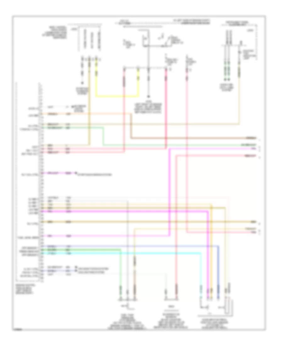
3.9L VIN 1, Engine Performance Wiring Diagram (1 of 4) for Pontiac G6 2008
 https://portal-diagnostov.com/license.html
Automotive Electricians Portal FZCO
Automotive Electricians Portal FZCO
https://portal-diagnostov.com/license.html
https://portal-diagnostov.com/license.html
Automotive Electricians Portal FZCO
Automotive Electricians Portal FZCOList of elements for 3.9L VIN 1, Engine Performance Wiring Diagram (1 of 4) for Pontiac G6 2008:
- (on left rear side of engine compt, on engine transmission stud, below upper coolant hose) g105
- 5v ref 1
- 5v ref 2
- A/c rly ctrl
- A/c sens sig
- Acc vol
- Air conditioning system
- App sens 1 sig
- App sens 2 sig
- Batt pos vol
- Body control module (bcm) (under right side of center console, near dash)
- C10
- Cluster/ theft fuse 10a
- Computer data lines system
- Cooling fans system
- Ecm fuse 51 10a
- Ecm ign fuse 3 10a
- Engine control module (ecm) (left side of engine compt)
- Evap vent ctrl
- Evaporative emissions (evap) canister vent solenoid valve (behind left side of rear fascia splash shield)
- Exterior lights system
- Fuel level sens sig
- Fuel pump rly ctrl
- Fuel tank sens sig
- G105 (on left rear side of engine compt, on engine transmission stud, below upper coolant hose)
- G109 (left front of engine compt, on left rear side of core support, between g101 & g104)
- Gnd
- Heated oxygen sensor (ho2s) bank 2 sensor 2 (in exhaust, after catalytic converter)
- Hi data bus+
- Hi data bus-
- Hi rly ctrl
- Ho2s hi sig
- Ho2s low ctrl
- Ho2s low sig
- Hot at all times
- Iat sens sig
- Ign 1 vol
- Ign mod fuse 43 15a
- Logic
- Low ref
- Low rly ctrl
- Maf sens sig
- Mass air flow (maf)/ intake air temperature (iat) sensor (on top right side of engine, at air cleaner)
- Mil ctrl
- Nca
- P (not used) x108
- Park/neutral sig
- Pnk
- Power distribution system
- Rly ctrl
- Rly ctrl run/crank
- Run/ crank relay 32
- Starter rly ctrl
- Starting/ charging system
- Stop lmp vol
- Tan
- Underhood fuse block (in left side of engine compt)
- Veh spd sig
- W/ panoramic sunroof
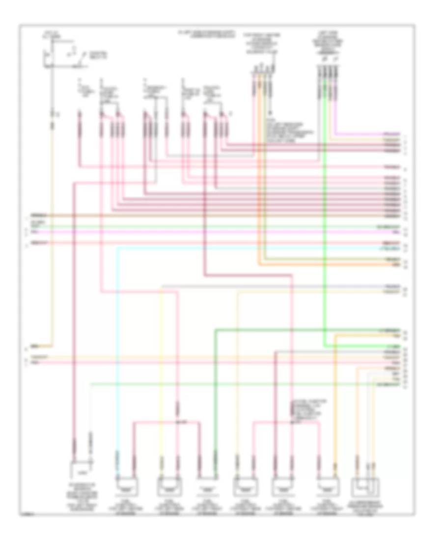
3.9L VIN 1, Engine Performance Wiring Diagram (2 of 4) for Pontiac G6 2008
 https://portal-diagnostov.com/license.html
Automotive Electricians Portal FZCO
Automotive Electricians Portal FZCO
https://portal-diagnostov.com/license.html
https://portal-diagnostov.com/license.html
Automotive Electricians Portal FZCO
Automotive Electricians Portal FZCOList of elements for 3.9L VIN 1, Engine Performance Wiring Diagram (2 of 4) for Pontiac G6 2008:
- A/c refrigerant pressure sensor (mounted on a/c line)
- A10
- Accelerator pedal position (app) sensor (attached to accelerator pedal)
- B11
- C11
- D11
- Emission 1 fuse 6 10a
- Emission 2 fuse 5 10a
- Etc fuse 2 15a
- Fuel pump
- Fuel pump & sender assembly (forward of rear axle, in fuel tank)
- Fuel pump fuse 25 15a
- Fuel tank pressure (ftp) sensor (on top of fuel pump & sender assembly, part of fuel pump & sender assembly)
- Fuel/pmp relay 37
- G301 (on right rear of passenger compt, under right rear seat back)
- G302 (on left rear of passenger compt, under left rear seat back, towards door)
- Heated oxygen sensor (ho2s) bank 1 sensor 2 (rear of exhaust, after catalytic converter)
- Hot at all times
- Injectors fuse 44 10a
- Nca
- Pnk
- Post 02 fuse 45 10a
- Pwr/trn relay 33
- Rear fuse block (left side of rear compt, behind left rear wheel well)
- Sensor fuel level
- Tan
- Underhood fuse block (in left side of engine compt)
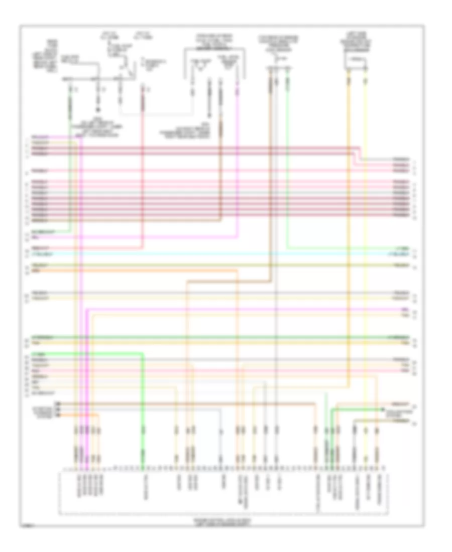
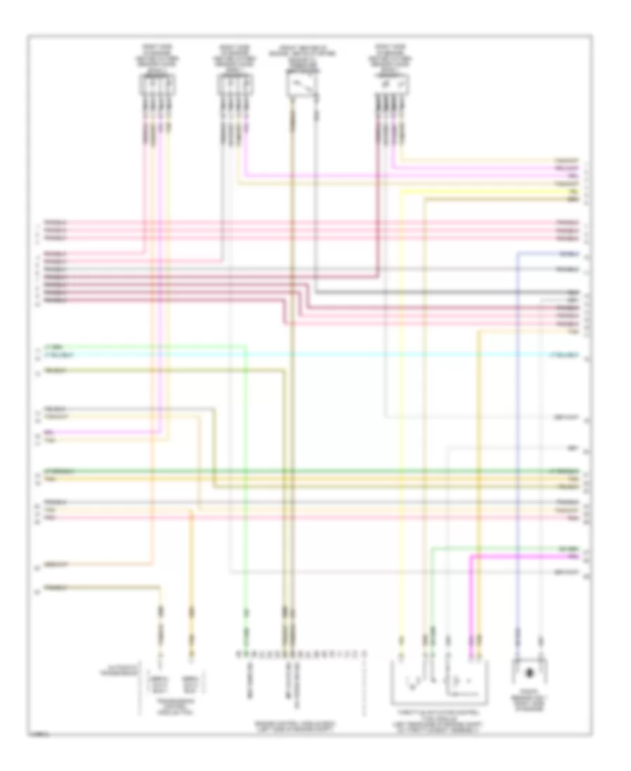
3.9L VIN 1, Engine Performance Wiring Diagram (3 of 4) for Pontiac G6 2008
 https://portal-diagnostov.com/license.html
Automotive Electricians Portal FZCO
Automotive Electricians Portal FZCO
https://portal-diagnostov.com/license.html
https://portal-diagnostov.com/license.html
Automotive Electricians Portal FZCO
Automotive Electricians Portal FZCOList of elements for 3.9L VIN 1, Engine Performance Wiring Diagram (3 of 4) for Pontiac G6 2008:
- (below engine oil pan) engine oil level sensor
- (below throttle actuator control module) engine coolant temperature (ect) sensor
- (left side of engine) knock sensor (ks) 1
- (right side of engine) knock sensor (ks) 2
- (top rear of engine) evaporative emissions (evap) canister purge solenoid valve
- Camshaft position (cmp) actuator solenoid valve (front of engine)
- Computer data lines system
- Engine oil pressure (eop) sensor (lower left center of engine)
- G201 (under center console, on front support bracket, next to g203)
- Gnd
- Heated oxygen sensor (ho2s) bank 1 sensor 1 (center of rear exhaust manifold)
- Ign
- Instrument panel cluster (ipc)
- Logic
- Malfunction indicator lamp
- Manifold absolute pressure (map) sensor (top rear of engine)
- Nca
- Pnk
- Serial data
- Tan
- Throttle actuator control (tac) module (top left rear of engine)
3.9L VIN 1, Engine Performance Wiring Diagram (4 of 4) for Pontiac G6 2008
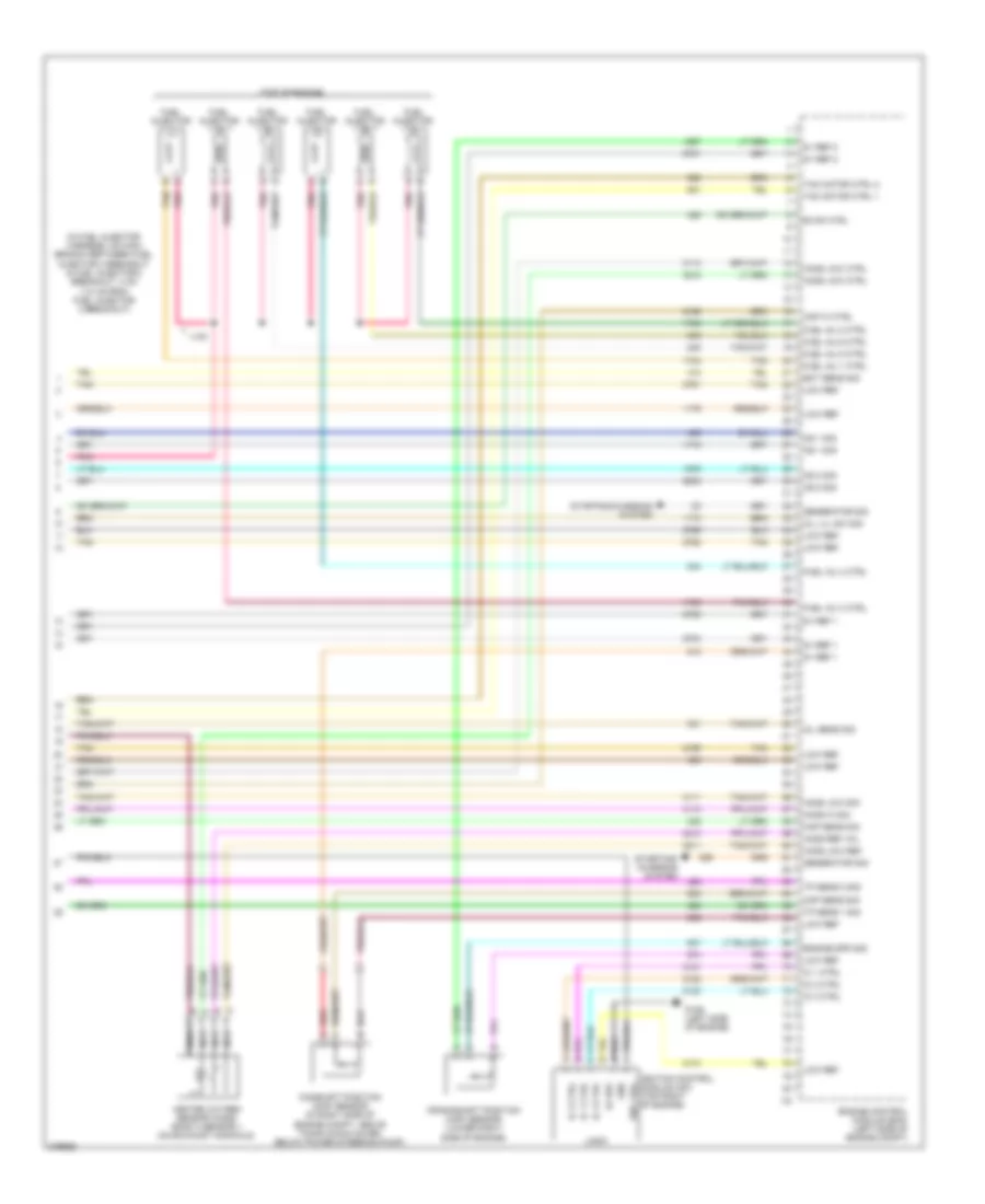 https://portal-diagnostov.com/license.html
Automotive Electricians Portal FZCO
Automotive Electricians Portal FZCO
https://portal-diagnostov.com/license.html
https://portal-diagnostov.com/license.html
Automotive Electricians Portal FZCO
Automotive Electricians Portal FZCOList of elements for 3.9L VIN 1, Engine Performance Wiring Diagram (4 of 4) for Pontiac G6 2008:
- (in fuel injector harness, on main branch between fuel injector 3 breakout & fuel injector 2 breakout, 4 cm (1.6 in) from fuel injector 2 breakout)
- (top of engine)
- 5v ref 1
- 5v ref 2
- Camshaft position (cmp) sensor (in right side of engine compt, above timing chain cover, below power steering pump)
- Cmp hi ctrl
- Cmp sens sig
- Crankshaft position (ckp) sensor (lower right side of engine)
- Ect sens sig
- Engine control module (ecm) (left side of engine compt)
- Engine spd sig
- Evap ctrl
- Fuel inj 1 ctrl
- Fuel inj 2 ctrl
- Fuel inj 3 ctrl
- Fuel inj 4 ctrl
- Fuel inj 5 ctrl
- Fuel inj 6 ctrl
- Fuel injector
- G106 (left side of engine)
- Generator sig
- Gnd
- Heated oxygen sensor (ho2s) bank 2 sensor 1 (on exhaust manifold)
- Ho2s hi sig
- Ho2s low ctrl
- Ho2s low ref
- Ho2s low sig
- Ho2s ref vol
- Ic 1 ctrl
- Ic 2 ctrl
- Ic 3 ctrl
- Ign 1 vol
- Ignition control module (icm) (top right of engine)
- J130
- Ks 1 sig
- Ks 2 sig
- Lo ref
- Logic
- Low ref
- Map sens sig
- Nca
- Oil lvl sw sig
- Oil sens sig
- Pnk
- Red
- Starting/ charging system
- Starting/charging system
- Tac motor ctrl 1
- Tac motor ctrl 2
- Tan
- Tp sens 1 sig
- Tp sens 2 sig
EXTERIOR LIGHTS
Exterior Lamps Wiring Diagram (1 of 2) for Pontiac G6 2008
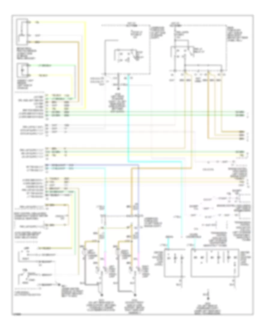 https://portal-diagnostov.com/license.html
Automotive Electricians Portal FZCO
Automotive Electricians Portal FZCO
https://portal-diagnostov.com/license.html
https://portal-diagnostov.com/license.html
Automotive Electricians Portal FZCO
Automotive Electricians Portal FZCOList of elements for Exterior Lamps Wiring Diagram (1 of 2) for Pontiac G6 2008:
- (3.5l/3.9l)
- (3.6l/2.4l)
- (not used)
- 2.4l
- 3.5l & 3.9l
- 3.6l
- 5v ref
- A12
- Ambient light sensor (left side of console)
- Auto
- Body control module (bcm) (under right side of center console, near dash)
- Brake pedal position sensor (in right side of brake pedal bracket)
- Brk pos sens sig
- C1 x1
- C10
- C12
- Center high mounted stop lamp (chmsl)
- Coupe/ convertible
- Drl amb lght sen sig
- Engine control module(ecm) (left side of engine compt)
- Except 2.4l
- Except 3.6l
- F11
- G101 (on left rear side of core support, between windshield washer fluid reservoir & g109)
- G102 (on right front side of core support, behind right headlamp assembly)
- G109 (left front of engine compt, on left rear side of core support, between g101 & g104)
- G201 (under center console, on front support bracket, next to g203)
- G302 (on left rear of passenger compt,
- Hazard sw sig
- Head
- Hi spd ser data +
- Hi spd ser data -
- Hot at all times
- Hvac control module (in lower center of dash, below radio)
- J112
- J113
- Left
- Left front marker lamp
- Left park/ turn signal lamp
- Lf trn sig vlt
- Lo spd ser data bus
- Low ref
- Lt trn sig sw
- Manual a/c
- Off
- Park
- Prk lamps fuse 6 10a
- Prk lmp rly cntl
- Prk lmp sw on sig
- Prk lp relay 27
- Rear fuse block (left side of rear compt, behind left rear wheel well)
- Rf trn sig vlt
- Right
- Right front marker lamp
- Right park/ turn signal lamp
- Rt trn sig sw
- Sedan
- Stop lp fuse 47 10a
- Stop lp relay
- Tan
- Transmission control module(tcm) (3.9l/3.5l) (left of engine compartment, near strut tower)
- Transmission control module(tcm) (left of engine compartment, near strut tower)
- Turn signal/ multifunction switch
- Under left rear seat back, towards door)
- Underhood fuse block (in left side of engine compt)
- W/ a/t
- W/o a/t
Exterior Lamps Wiring Diagram (2 of 2) for Pontiac G6 2008
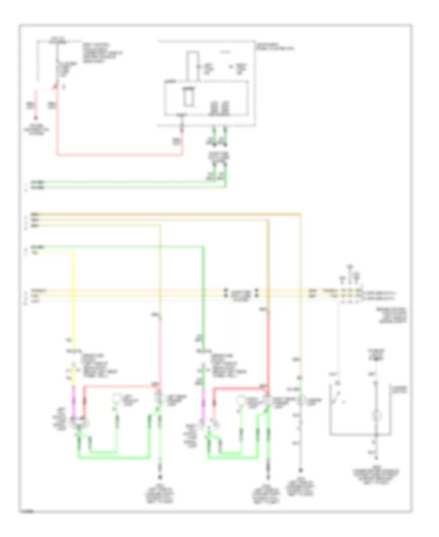 https://portal-diagnostov.com/license.html
Automotive Electricians Portal FZCO
Automotive Electricians Portal FZCO
https://portal-diagnostov.com/license.html
https://portal-diagnostov.com/license.html
Automotive Electricians Portal FZCO
Automotive Electricians Portal FZCOList of elements for Exterior Lamps Wiring Diagram (2 of 2) for Pontiac G6 2008:
- 2.4l
- 3.5l/ 3.9l
- 3.6l
- Batt
- Body control module (bcm) (under right side of center console, near dash)
- C11
- Chime
- Cluster/ theft fuse 10a
- Computer data lines system
- Engine control module (ecm) (left side of engine compt)
- G203 (under center console, on right side of front support bracket, next to g201)
- G401 (left side of luggage compt, on back wall, next to g403)
- G403 (left side of luggage compt, on back wall, next to g401)
- Hazard switch
- Hi spd ser data +
- Hi spd ser data -
- Hot at all times
- Instrument panel cluster (ipc)
- Interior lights system
- Left backup lamp
- Left rear marker lamp
- Left tail/ stop & a
- Left turn ind
- License lamp
- Logic
- Low spd ser data
- Power distribution system
- Rear fuse block (left side of rear compt, behind left rear wheel well)
- Red
- Right backup lamp
- Right rear marker lamp
- Right tail/ stop & turn signal lamp
- Right turn ind
- Tan
- Turn signal lamp
2.4L VIN B
2.4L VIN B, Backup Lamps Wiring Diagram for Pontiac G6 2008
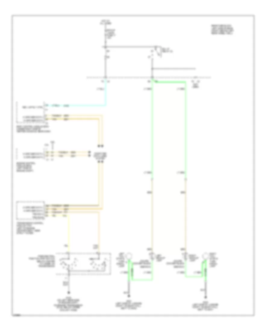 https://portal-diagnostov.com/license.html
Automotive Electricians Portal FZCO
Automotive Electricians Portal FZCO
https://portal-diagnostov.com/license.html
https://portal-diagnostov.com/license.html
Automotive Electricians Portal FZCO
Automotive Electricians Portal FZCOList of elements for 2.4L VIN B, Backup Lamps Wiring Diagram for Pontiac G6 2008:
- (coupe/ convertible)
- (not used)
- 2.4l
- 3.5l
- B/u lp relay 33
- Bck/up lamps fuse 17 10a
- Body control module (bcm) (under right side of center console, near dash)
- Computer data lines system
- Engine control module (ecm) (left side of engine compt)
- G (sedan)
- G105 (on left rear side of engine compt,
- G401 (left side of luggage compt, on back wall, next to g403)
- G403 (left side of luggage compt, on back wall, next to g401)
- Hi spd ser data +
- Hi spd ser data -
- Hot at all times
- Left backup lamp
- Left tail/ stop & turn signal lamp
- On engine transmission stud, below upper coolant hose)
- Park/neutral position (pnp) switch (below master cylinder, on transmission)
- Rear fuse block (left side of rear compt, behind left rear wheel well)
- Rev lmp rly ctrl
- Right backup lamp
- Right tail/ stop & turn signal lamp
- Tan
- Transmission control module (tcm) (left of engine compartment, near strut tower)
- Trs sig a
- Trs sig b
3.5L VIN N
3.5L VIN N, Backup Lamps Wiring Diagram for Pontiac G6 2008
 https://portal-diagnostov.com/license.html
Automotive Electricians Portal FZCO
Automotive Electricians Portal FZCO
https://portal-diagnostov.com/license.html
https://portal-diagnostov.com/license.html
Automotive Electricians Portal FZCO
Automotive Electricians Portal FZCOList of elements for 3.5L VIN N, Backup Lamps Wiring Diagram for Pontiac G6 2008:
- (coupe/ convertible)
- (not used)
- 2.4l
- 3.5l
- B/u lp relay 33
- Bck/up lamps fuse 17 10a
- Body control module (bcm) (under right side of center console, near dash)
- Computer data lines system
- Engine control module (ecm) (left side of engine compt)
- G (sedan)
- G105 (on left rear side of engine compt,
- G401 (left side of luggage compt, on back wall, next to g403)
- G403 (left side of luggage compt, on back wall, next to g401)
- Hi spd ser data +
- Hi spd ser data -
- Hot at all times
- Left backup lamp
- Left tail/ stop & turn signal lamp
- On engine transmission stud, below upper coolant hose)
- Park/neutral position (pnp) switch (below master cylinder, on transmission)
- Rear fuse block (left side of rear compt, behind left rear wheel well)
- Rev lmp rly ctrl
- Right backup lamp
- Right tail/ stop & turn signal lamp
- Tan
- Transmission control module (tcm) (left of engine compartment, near strut tower)
- Trs sig a
- Trs sig b
3.6L VIN 7
3.6L VIN 7, Backup Lamps Wiring Diagram for Pontiac G6 2008
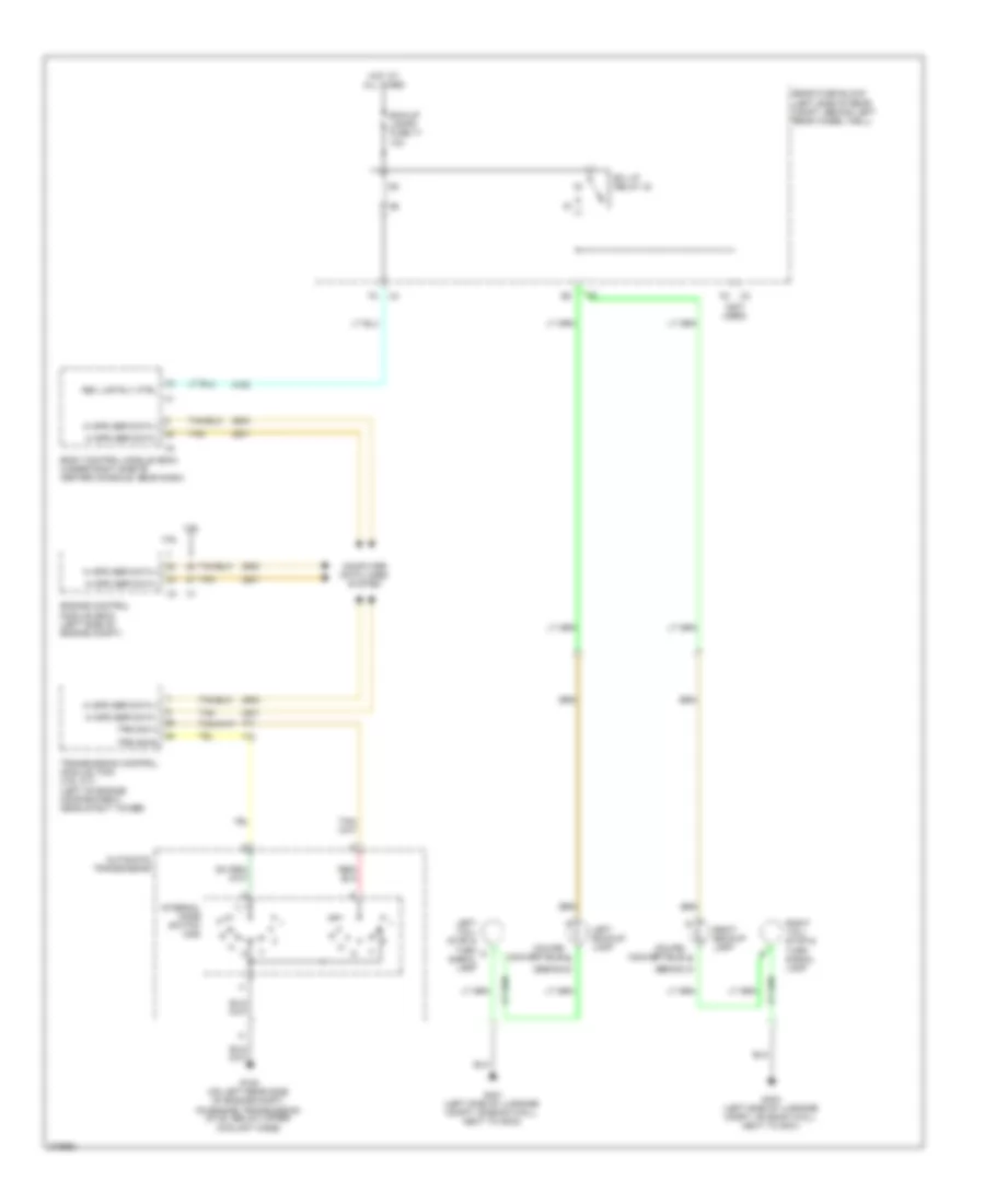 https://portal-diagnostov.com/license.html
Automotive Electricians Portal FZCO
Automotive Electricians Portal FZCO
https://portal-diagnostov.com/license.html
https://portal-diagnostov.com/license.html
Automotive Electricians Portal FZCO
Automotive Electricians Portal FZCOList of elements for 3.6L VIN 7, Backup Lamps Wiring Diagram for Pontiac G6 2008:
- (coupe/ convertible) b
- (not used)
- 3.6l
- 3.9l
- Automatic transmission
- B/u lp relay 33
- Bck/up lamps fuse 17 10a
- Body control module (bcm) (under right side of center console, near dash)
- Computer data lines system
- Engine control module (ecm) (left side of engine compt)
- G (sedan)
- G105 (on left rear side of engine compt,
- G401 (left side of luggage compt, on back wall, next to g403)
- G403 (left side of luggage compt, on back wall, next to g401)
- Hi spd ser data +
- Hi spd ser data -
- Hot at all times
- Internal mode switch (ims)
- Left backup lamp
- Left tail/ stop & turn signal lamp
- On engine transmission stud, below upper coolant hose)
- Rear fuse block (left side of rear compt, behind left rear wheel well)
- Rev lmp rly ctrl
- Right backup lamp
- Right tail/ stop & turn signal lamp
- Tan
- Transmission control module (tcm) (3.9l a/t) (left of engine compartment, near strut tower)
- Trs sig a
- Trs sig b
3.9L VIN 1
3.9L VIN 1, Backup Lamps Wiring Diagram for Pontiac G6 2008
 https://portal-diagnostov.com/license.html
Automotive Electricians Portal FZCO
Automotive Electricians Portal FZCO
https://portal-diagnostov.com/license.html
https://portal-diagnostov.com/license.html
Automotive Electricians Portal FZCO
Automotive Electricians Portal FZCOList of elements for 3.9L VIN 1, Backup Lamps Wiring Diagram for Pontiac G6 2008:
- (coupe/ convertible) b
- (not used)
- 3.6l
- 3.9l
- Automatic transmission
- B/u lp relay 33
- Bck/up lamps fuse 17 10a
- Body control module (bcm) (under right side of center console, near dash)
- Computer data lines system
- Engine control module (ecm) (left side of engine compt)
- G (sedan)
- G105 (on left rear side of engine compt,
- G401 (left side of luggage compt, on back wall, next to g403)
- G403 (left side of luggage compt, on back wall, next to g401)
- Hi spd ser data +
- Hi spd ser data -
- Hot at all times
- Internal mode switch (ims)
- Left backup lamp
- Left tail/ stop & turn signal lamp
- On engine transmission stud, below upper coolant hose)
- Rear fuse block (left side of rear compt, behind left rear wheel well)
- Rev lmp rly ctrl
- Right backup lamp
- Right tail/ stop & turn signal lamp
- Tan
- Transmission control module (tcm) (3.9l a/t) (left of engine compartment, near strut tower)
- Trs sig a
- Trs sig b
GROUND DISTRIBUTION
Ground Distribution Wiring Diagram (1 of 3) for Pontiac G6 2008
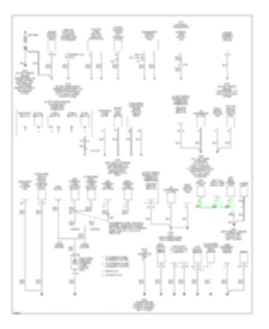 https://portal-diagnostov.com/license.html
Automotive Electricians Portal FZCO
Automotive Electricians Portal FZCO
https://portal-diagnostov.com/license.html
https://portal-diagnostov.com/license.html
Automotive Electricians Portal FZCO
Automotive Electricians Portal FZCOList of elements for Ground Distribution Wiring Diagram (1 of 3) for Pontiac G6 2008:
- (2.4l, 3.9l)
- (2.4l/3.5l) park/ neutral position (pnp) switch
- (3.5l/3.9l) ignition control module (icm)
- (3.6l)
- (a/t) automatic transmission
- (if equipped) adjustable pedal module
- (if equipped) electronic brake control module (ebcm)
- (if equipped) right steering wheel controls switch
- (if equipped) vehicle communi- cation interface module (vcim)
- (in left side of engine compartment) underhood fuse block
- (in left side of engine compt) underhood fuse block
- (in steering wheel controls harness, under left side of inflatable restraint steering wheel module, 17 cm (6.8 in) from x276)
- 2.4l/3.9l
- 3 spoke
- 3.9l
- 4 spoke
- 87a
- A/c compressor clutch
- A/t
- A12
- Automatic a/c
- Battery
- Body control module (bcm)
- Brake fluid level switch
- C (except 2.4l) (2.4l)
- C10
- Cool/fan ser/par relay 29
- Data link connector (dlc)
- Engine control module (ecm)
- Frt fog relay 36
- G103 (on left side of engine compartment, on top of left strut tower)
- G104 (on left side of engine compartment, on core support, between left inflatable restraint front end sensor & g109)
- G105 (on left rear side of engine compartment, on engine transmission stud, below upper coolant hose)
- G106 (2.4l: left rear of engine) (3.5l & 3.6l: on front of engine, at transmission stud, near pnp switch) (3.9l: left side of engine)
- G108 (3.6l) (right rear corner of cylinder head)
- G109 (left front of engine compartment, on left rear side of core support, between g101 & g104)
- G201 (under center console, on front support bracket, next to g203)
- G401 (left side of luggage compartment, on back wall, next to g403)
- Horn switch
- Hvac control module
- Inflatable restraint steering wheel module coil
- Instrument panel cluster (ipc)
- Intake manifold tuning (imt) solenoid valve
- Internal mode switch (ims)
- J201
- Left back-up lamp
- Left rear marker lamp
- Left steering wheel controls
- Left steering wheel controls switch
- Left tail/ stop & turn signal lamp
- License lamp
- Manual a/c
- Mass air flow (maf)/ intake air temperature (iat) sensor
- Nca
- Power steering control module
- Radio
- Right engine cooling fan
- Right steering wheel controls
- Run/crank relay 32
- Start relay 31
- Theft deterrent control module
- Transmission control module (tcm)
- Turn signal/ multifunction switch
- W/ cruise control
- W/ steering wheel accessory control
- W/o cruise control
- W/o steering wheel accessory control
- Windshield wiper motor
- Wiper 1 relay 39
- Wiper 2 relay 40
- X100
Ground Distribution Wiring Diagram (2 of 3) for Pontiac G6 2008
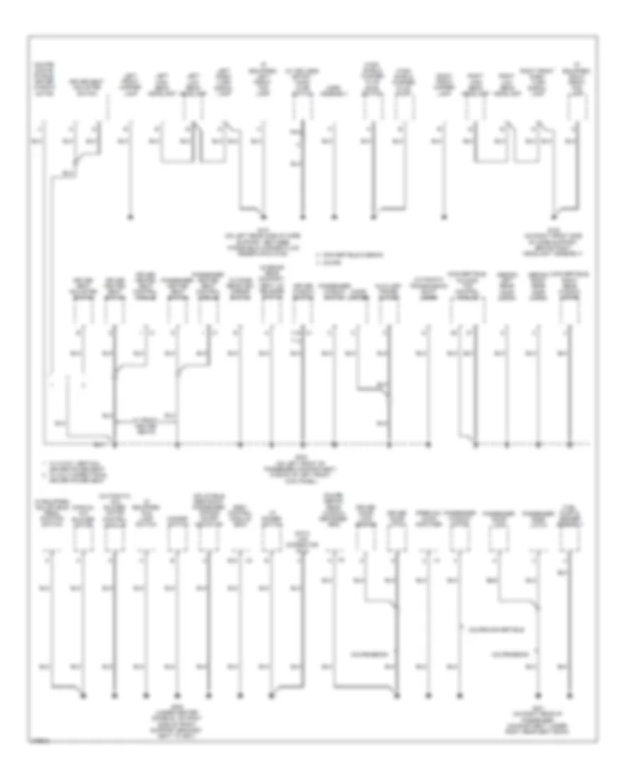 https://portal-diagnostov.com/license.html
Automotive Electricians Portal FZCO
Automotive Electricians Portal FZCO
https://portal-diagnostov.com/license.html
https://portal-diagnostov.com/license.html
Automotive Electricians Portal FZCO
Automotive Electricians Portal FZCOList of elements for Ground Distribution Wiring Diagram (2 of 3) for Pontiac G6 2008:
- (automatic a/c) blower motor control module
- (convertible) folding top control module
- (convertible) right rear window motor
- (coupe/ conve- rtible) driver window motor
- (coupe/ sedan) rear window defogger grid
- (if equipped) adjustable pedal position switch
- (if equipped) fog lamp switch
- (if equipped) left front fog lamp
- (if equipped) right front fog lamp
- (manual a/c) blower motor
- (premium) audio amplifier
- (sedan) left rear door latch
- (sedan) right rear door latch
- (w/ keyless entry) hood ajar switch
- Automatic transmission shift lever
- Auxiliary power outlet
- Body control module (bcm)
- Cigar lighter
- Convertible & sedan
- Coupe
- Coupe/convertible
- Coupe/sedan
- Data link connector (dlc)
- Driver door latch
- Driver door lock switch
- Driver heated seat control module
- Driver heated seat switch
- Driver seat adjuster switch
- Driver window switch
- E12
- Fuel pump & sender assembly
- G101 (on left rear side of core support, between windshield washer fluid reservoir & g109)
- G102 (on right front side of core support, behind right headlight assembly)
- G203 (under center console, on right side of front support bracket, next to g201)
- G301 (on right rear of passenger compartment, under right rear seat back)
- G303 (on left front of passenger compartment, in back of left front kick panel)
- Hazard switch
- Horn assembly
- I/p dimmer switch
- Inflatable restraint passenger air bag on/off indicator
- Interior rear compart- ment lid release switch
- Left front marker lamp
- Left high beam headlamp
- Left low beam headlamp
- Left park/ turn signal lamp
- Nca
- Outside rearview mirror switch
- Passenger door latch
- Passenger door lock
- Passenger heated seat control module
- Passenger heated seat switch
- Passenger window motor
- Passenger window switch
- Right front marker lamp
- Right front park/ turn signal lamp
- Right high beam headlamp
- Right low beam headlamp
- W/ 2-way vertical driver power seat w/ multi-directional driver power seat
- W/ front heater seats
- Wind- shield washer fluid level switch
- Wind- shield washer fluid pump
Ground Distribution Wiring Diagram (3 of 3) for Pontiac G6 2008
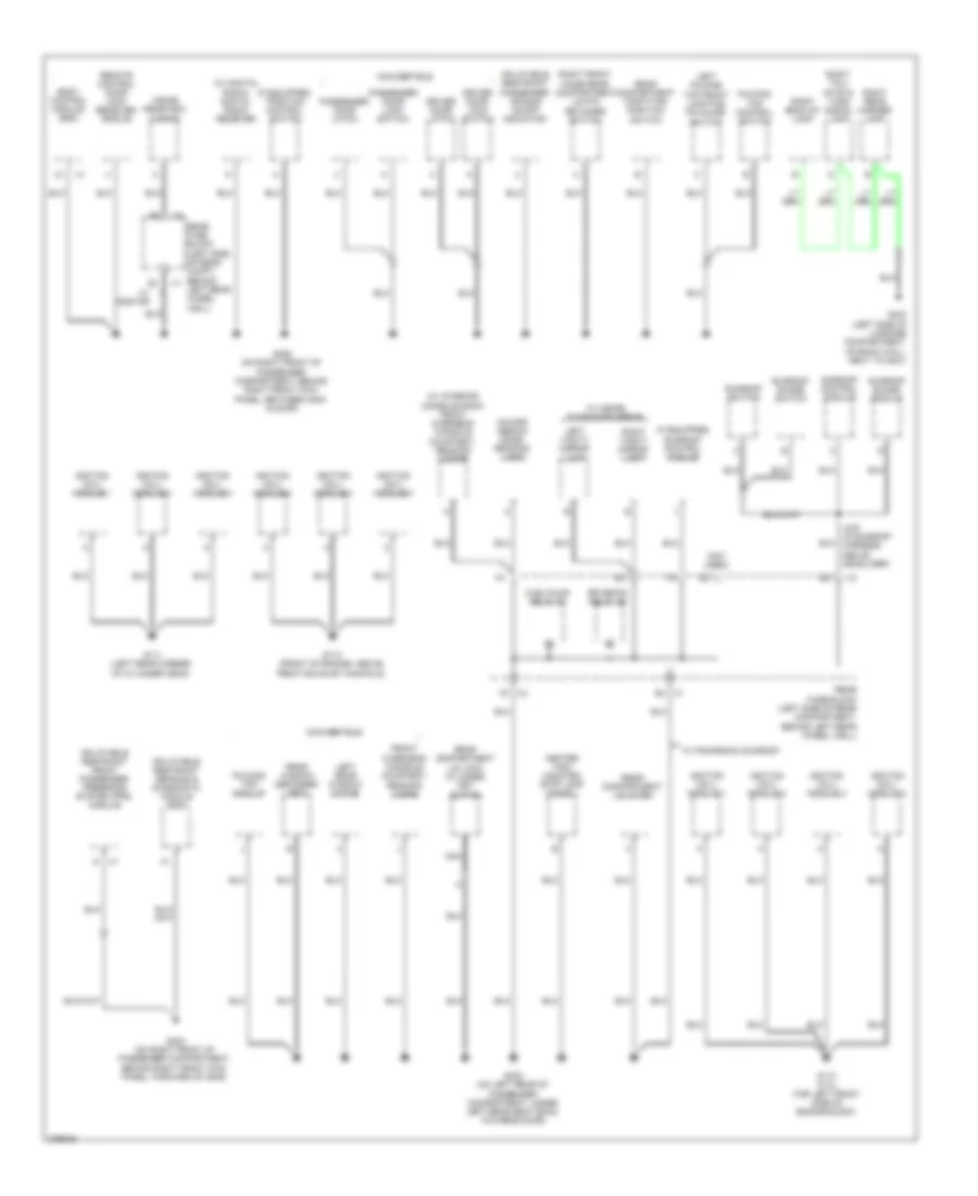 https://portal-diagnostov.com/license.html
Automotive Electricians Portal FZCO
Automotive Electricians Portal FZCO
https://portal-diagnostov.com/license.html
https://portal-diagnostov.com/license.html
Automotive Electricians Portal FZCO
Automotive Electricians Portal FZCOList of elements for Ground Distribution Wiring Diagram (3 of 3) for Pontiac G6 2008:
- (coupe/ sedan) dome/ reading lamp
- (if equipped) sunroof control module
- (if equipped) traction control switch
- (not used)
- (w/ digital radio) digital radio receiver
- (w/ interior console roof) front overhead console courtesy/ reading lamps
- Body control module (bcm)
- Center high mounted stop lamp (chmsl)
- Convertible
- Driver door latch
- Driver door lock switch
- Folding top control switch
- Folding top module
- Front overhead console courtesy/ reading lamps
- Fuel/pump relay 37
- G110 (2.4l) (top left front side of engine block)
- G111 (left rear corner of cylinder head)
- G113 (front of engine, above front exhaust manifold)
- G302 (on left rear of passenger compartment, under left rear seat back, towards door)
- G304 (on right front of passenger compartment, behind right front kick panel, forward of g305)
- G305 (on right front of passenger compartment, behind right front kick panel, between g304 & door)
- G403 (left side of luggage compartment, on back wall, next to g401)
- Ignition coil/ module 1
- Ignition coil/ module 2
- Ignition coil/ module 3
- Ignition coil/ module 4
- Ignition coil/ module 5
- Ignition coil/ module 6
- Inflatable restraint front passenger presence system (pps) module
- Inflatable restraint passenger air bag on/off indicator
- Inflatable restraint sensing & diagnostic module (sdm)
- Inside rearview mirror
- J403 (in sunroof harness, above headliner)
- Left folding top front locating pin guide switch
- Left rear window motor
- Left vanity mirror lamp
- Nca
- Passenger door latch
- Passenger door lock switch
- Rear compartment lid latch
- Rear compartment lid lock cylinder key switch
- Rear compartment partition position switch
- Rear fuse block (left side of rear compartment, behind left rear wheel well)
- Rear fuse block (left side of rear compt, behind x1 left rear wheel well)
- Rear window defogger grid
- Remote control door lock receiver (rcdlr)
- Right back-up lamp
- Right front hinge rear compartment lid pin retainer switch
- Right rear marker lamp
- Right tail/ stop & turn signal lamp
- Right vanity mirror lamp
- Rr defog relay 26
- Sunroof control module
- Sunroof shade module
- Sunroof shade switch
- Sunroof switch
- W/ inside sunshade mirror
- W/ onstar
- W/ panoromic sunroof
HEADLIGHTS
Headlights Wiring Diagram for Pontiac G6 2008
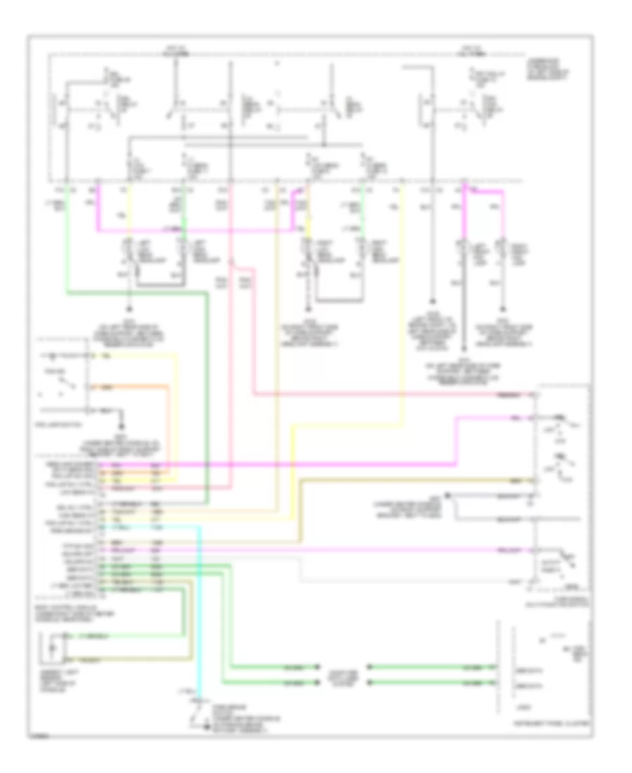 https://portal-diagnostov.com/license.html
Automotive Electricians Portal FZCO
Automotive Electricians Portal FZCO
https://portal-diagnostov.com/license.html
https://portal-diagnostov.com/license.html
Automotive Electricians Portal FZCO
Automotive Electricians Portal FZCOList of elements for Headlights Wiring Diagram for Pontiac G6 2008:
- (on right front side of core support, behind right headlamp assembly)
- (under center console, on right side of front support bracket, next to g201)
- A12
- Ambient light sensor (left side of console)
- Auto
- B12
- Body control module (under right side of center console, near dash)
- C10
- Computer data lines system
- D10
- Drl fuse 46 15a
- Drl relay
- Drl rly ctrl
- F f
- F12 x2
- Fog ind
- Fog lamp switch
- Fog lmp rly ctrl
- Fog lmp sw sig
- Frt fog lp fuse 10 15a
- Frt fog relay
- Ftp
- Ftp sw sig
- G101 (on left rear side of core support, between windshield washer fluid reservoir & g109)
- G102
- G102 (on right front side of core support, behind right headlamp assembly)
- G109 (left front of engine compt, on left rear side of core support, between g101 & g104)
- G201 (under center console, on front support bracket, next to g203)
- G203
- Hdlmps off
- Hdlmps on
- Head
- Headlamp dimmer sw hi beam sig
- Hi/ beam relay
- High
- High beam in
- High beam ind
- Hot at all times
- Instrument panel cluster
- Left front fog lamp
- Left high beam headlamp
- Left low beam headlamp
- Lh low fuse 7 10a
- Lo/ beam relay
- Logic
- Low
- Low beam in
- Lt hi beam fuse 11 10a
- Lt sen low ref
- Lt sen sig
- Off
- Park
- Park brake sw
- Park brake switch (under center console, on parking brake ratchet assembly)
- Right front fog lamp
- Right high beam headlamp
- Right low beam headlamp
- Rt hi beam fuse 12 10a
- Rt low beam fuse 9 10a
- Ser data
- Turn signal/ multi-function switch
- Underhood fuse block (in left side of engine compt)
HORN
Horn Wiring Diagram for Pontiac G6 2008
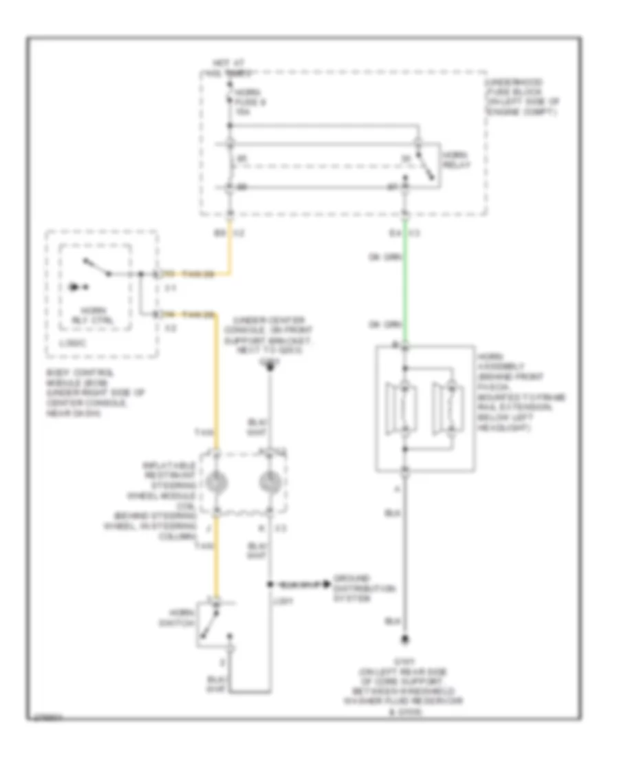 https://portal-diagnostov.com/license.html
Automotive Electricians Portal FZCO
Automotive Electricians Portal FZCO
https://portal-diagnostov.com/license.html
https://portal-diagnostov.com/license.html
Automotive Electricians Portal FZCO
Automotive Electricians Portal FZCOList of elements for Horn Wiring Diagram for Pontiac G6 2008:
- & g109)
- (under center console, on front support bracket, next to g203)
- B9 x2
- Body control module (bcm) (under right side of center console, near dash)
- E4 x3
- G101 (on left rear side of core support, between windshield washer fluid reservoir
- G201
- Ground distribution system
- Horn assembly (behind front fascia, mounted to frame rail extension, below left headlight)
- Horn fuse 8 15a
- Horn relay
- Horn rly ctrl
- Horn switch
- Hot at all times
- Inflatable restraint steering wheel module coil (behind steering wheel, in steering column)
- J201
- Logic
- Tan
- Underhood fuse block (in left side of engine compt)
- X2 k
- X3 k
INSTRUMENT CLUSTER
Instrument Cluster Wiring Diagram (1 of 2) for Pontiac G6 2008
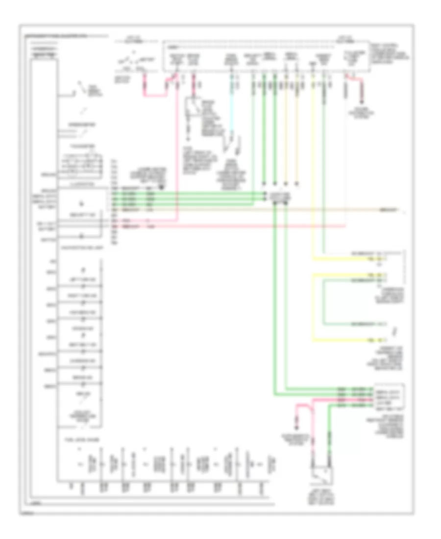 https://portal-diagnostov.com/license.html
Automotive Electricians Portal FZCO
Automotive Electricians Portal FZCO
https://portal-diagnostov.com/license.html
https://portal-diagnostov.com/license.html
Automotive Electricians Portal FZCO
Automotive Electricians Portal FZCOList of elements for Instrument Cluster Wiring Diagram (1 of 2) for Pontiac G6 2008:
- (bcm)
- (ebcm)
- (ecm/ pcm)
- (ecm/pcm)
- (sdm)
- (under center console, on front support bracket, next to g203) g201
- 000000 trip
- Abs ind
- Acc
- Air bag ind
- Ambient air temperature sensor (on left side of front impact bar, behind grille)
- Ambient sens sig
- Battery
- Body control module (bcm) (under right side of center console, near dash)
- Brake fluid level
- Brake fluid level switch (mounted under center of brake fluid reservoir)
- Brake ind
- Charging ind
- Cluster/ theft fuse 10a
- Computer data lines system
- Coolant temperature gauge
- Cruise ind
- Fuel level gauge
- G109 (left front of engine compt, on left rear side of core support, between g101 & g104)
- Gnd
- Ground
- High beam ind
- Hot at all times
- Ign
- Ign 1 volt
- Ignition
- Ignition (run/ start)
- Ignition switch
- Illumination
- Ind
- Inflatable restraint sensing & diagnostic module (sdm) (under center console)
- Instrument panel cluster (ipc)
- Left seat belt switch (part of seat belt buckle)
- Left turn ind
- Logic
- Low fuel warning ind
- Low ref
- Low stability
- Malfunction ind lamp
- Nca
- Off
- Off ind stability
- Off ind traction
- Oil level ind
- On ind traction
- Park brake switch
- Park brake switch (under center console, on parking brake ratchet assembly)
- Pcm) (ecm/
- Pnk
- Power distribution system
- Right turn ind
- Run
- Seat belt ind
- Seat belt sw
- Security ind
- Security ind signal
- Serial bus
- Serial data
- Service vehicle
- Soon ind
- Speedometer
- Start
- Tachometer
- Tan
- Temp ind coolant engine
- Trip reset switch
- Underhood fuse block (in left side of engine compt)
- Vf display
Instrument Cluster Wiring Diagram (2 of 2) for Pontiac G6 2008
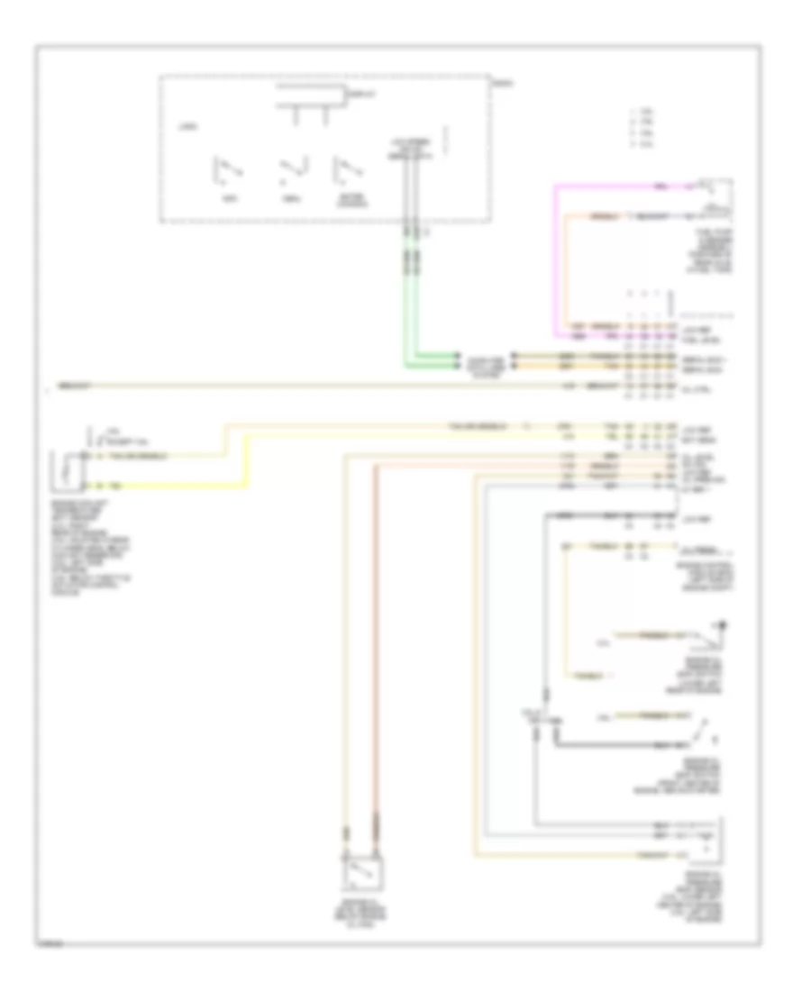 https://portal-diagnostov.com/license.html
Automotive Electricians Portal FZCO
Automotive Electricians Portal FZCO
https://portal-diagnostov.com/license.html
https://portal-diagnostov.com/license.html
Automotive Electricians Portal FZCO
Automotive Electricians Portal FZCOList of elements for Instrument Cluster Wiring Diagram (2 of 2) for Pontiac G6 2008:
- (lower left rear of engine)
- 2.4l
- 3.5l
- 3.5l & 3.9l
- 3.6l
- 3.9l
- 5v ref 1
- B10
- Computer data lines system
- Display
- Ect sens
- Engine control module (ecm) (left side of engine compt)
- Engine coolant temperature (ect) sensor (2.4l: right rear of engine) (3.5l: mounted in rear cylinder head, below coolant reservoir) (3.6l: left side of engine) (3.9l: below throttle actuator control module)
- Engine oil level sensor (below engine oil pan)
- Engine oil pressure (eop) sensor (3.9l: lower left center of engine) (3.5l: left side of engine)
- Engine oil pressure (eop) switch
- Engine oil pressure (eop) switch (front center of engine, above starter)
- Enter (canada)
- Except 3.6l
- Fuel level
- Fuel pump & sender assembly (forward of rear axle, in fuel tank)
- Info
- Logic
- Low ref
- Low speed gmlan serial data
- Menu
- Mil ctrl
- Oil level sw sig low ref oil pres sig
- Oil press
- Radio
- Serial bus +
- Serial bus -
- Tan
INTERIOR LIGHTS
Courtesy Lamps Wiring Diagram for Pontiac G6 2008
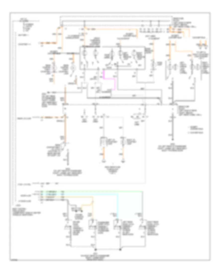 https://portal-diagnostov.com/license.html
Automotive Electricians Portal FZCO
Automotive Electricians Portal FZCO
https://portal-diagnostov.com/license.html
https://portal-diagnostov.com/license.html
Automotive Electricians Portal FZCO
Automotive Electricians Portal FZCOList of elements for Courtesy Lamps Wiring Diagram for Pontiac G6 2008:
- (if eq- uipped)
- (not used)
- (on left rear of passenger compt, under left rear seat back, towards door)
- (sedan) (in rear of left rear door)
- (sedan) (in rear of right rear door)
- A10
- A5 x4
- Ajar
- Assembly (in rear of driver door)
- Battery +
- Body control module (bcm) (under right side of center console, near dash)
- C5 x1
- Convertible
- Courtesy v+
- Ctsy lp ctrl
- D8 x1
- D9 x1
- Dome lamp
- Dome/ reading lamps
- Door
- Door ajar
- Driver door latch ajar
- E5 x3
- E6 x1
- Except
- Except convertible
- F2 x4
- F5 x3
- From rear fuse fuse block (diagram 1 of 1)
- Front overhead console courtesy/ reading lamps
- G301 (on right rear of passenger compt, under right rear seat back)
- G302
- G302 (on left rear of passenger compt, under left rear seat back, towards door)
- Hot at all times
- Interior lights fuse 10a
- Left i/p courtesy lamp
- Left rear door latch assembly ajar
- Left rear reading lamp
- Left vanity mirror lamp (if eq- uipped)
- Lf door ajar
- Logic
- Off
- Passenger door latch assembly (in rear of passenger door)
- Power windows system
- Rear compar- tment courtesy lamp
- Rear compartment lid latch (mounted to rear center of compt lid)
- Rear fuse block (left side of rear compt, behind left rear wheel well)
- Rear lid ajar
- Right i/p courtesy lamp
- Right rear door latch assembly ajar
- Right rear reading lamp
- Right vanity mirror lamp
- To left & right courtesy lamp (diagram 1 of 1)
- W/ interior console roof
- W/ sunroof
- W/o sunroof
- X1 d9
Instrument Illumination Wiring Diagram for Pontiac G6 2008
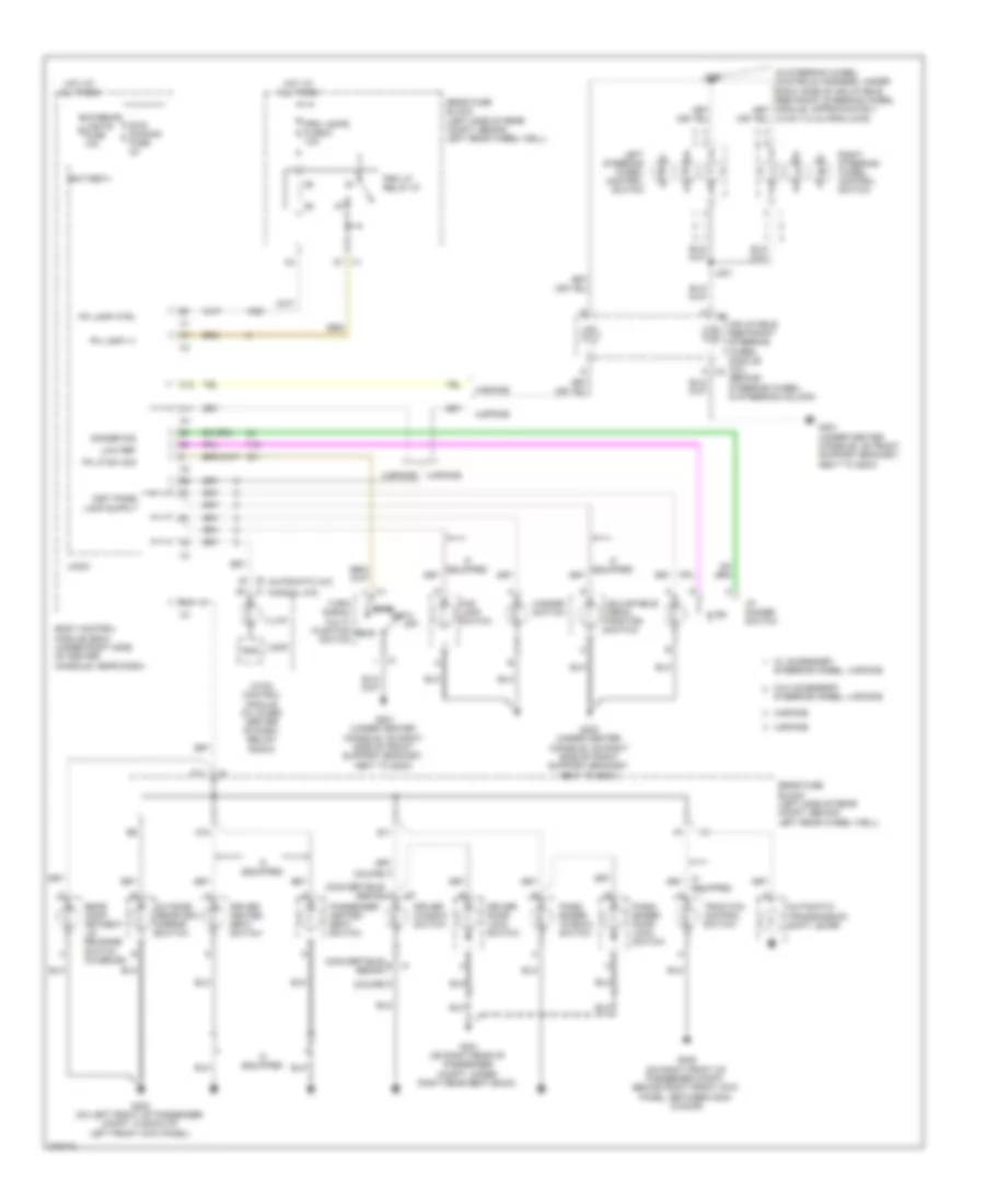 https://portal-diagnostov.com/license.html
Automotive Electricians Portal FZCO
Automotive Electricians Portal FZCO
https://portal-diagnostov.com/license.html
https://portal-diagnostov.com/license.html
Automotive Electricians Portal FZCO
Automotive Electricians Portal FZCOList of elements for Instrument Illumination Wiring Diagram for Pontiac G6 2008:
- (automatic a/c)
- (convertible/ b x1
- (convertible/ sedan)
- (coupe)
- (manual a/c)
- (under center console, on right side of front support bracket, next to g203)
- 18 cm (7.2 in) from x276)
- 3-spoke
- 4-spoke
- Adjustable pedal position switch
- Auto
- Automatic transmission shift lever
- B1 x1
- B12
- Battery+
- Body control module (bcm) (under right side of center console, near dash)
- C11
- C12
- D1 x1
- D10
- Dimmer sig
- Driver door lock switch
- Driver heated seat switch
- Driver window switch
- E11
- Equipped
- F11
- Fog lamp switch
- G201
- G201 (under center console, on front support bracket, next to g203)
- G203 (under center console, on right side of front support bracket, next to g201)
- G301 (on right rear of passenger compt, under right rear seat back)
- G303 (on left front of passenger compt, in back of left front kick panel)
- G305 (on right front of passenger compt, behind right front kick panel, between g304 & door)
- Gnd
- Hazard switch
- Head
- Hot at all times
- Hvac control module (in lower center of dash, below radio)
- I/p dimmer switch
- If equipped
- Illum
- Inflatable restraint steering wheel module coil (behind steering wheel, in steering column)
- Inst panel
- Interior lights fuse 10a
- J201
- J202
- Left steering wheel control switch
- Logic
- Low ref
- Off
- Outside rearview mirror switch
- Park
- Pass- enger door lock switch
- Pass- enger window switch
- Passenger heated seat switch
- Pk lamp ctrl
- Pk lamp v+
- Pk lp sw sig
- Prk lamps fuse 6 10a
- Prk lp relay 27
- Rear comp- artment lid release switch (interior)
- Rear fuse block (left side of rear compt, behind left rear wheel well)
- Right steering wheel control switch
- Sedan)
- Steering wheel, 4-spoke
- Swc dimming fuse 2a
- Traction control switch
- Turn/ signal multi- function switch
- W/ accessory
- W/o accessory
- X2 k
POWER DISTRIBUTION
Power Distribution Wiring Diagram (1 of 5) for Pontiac G6 2008
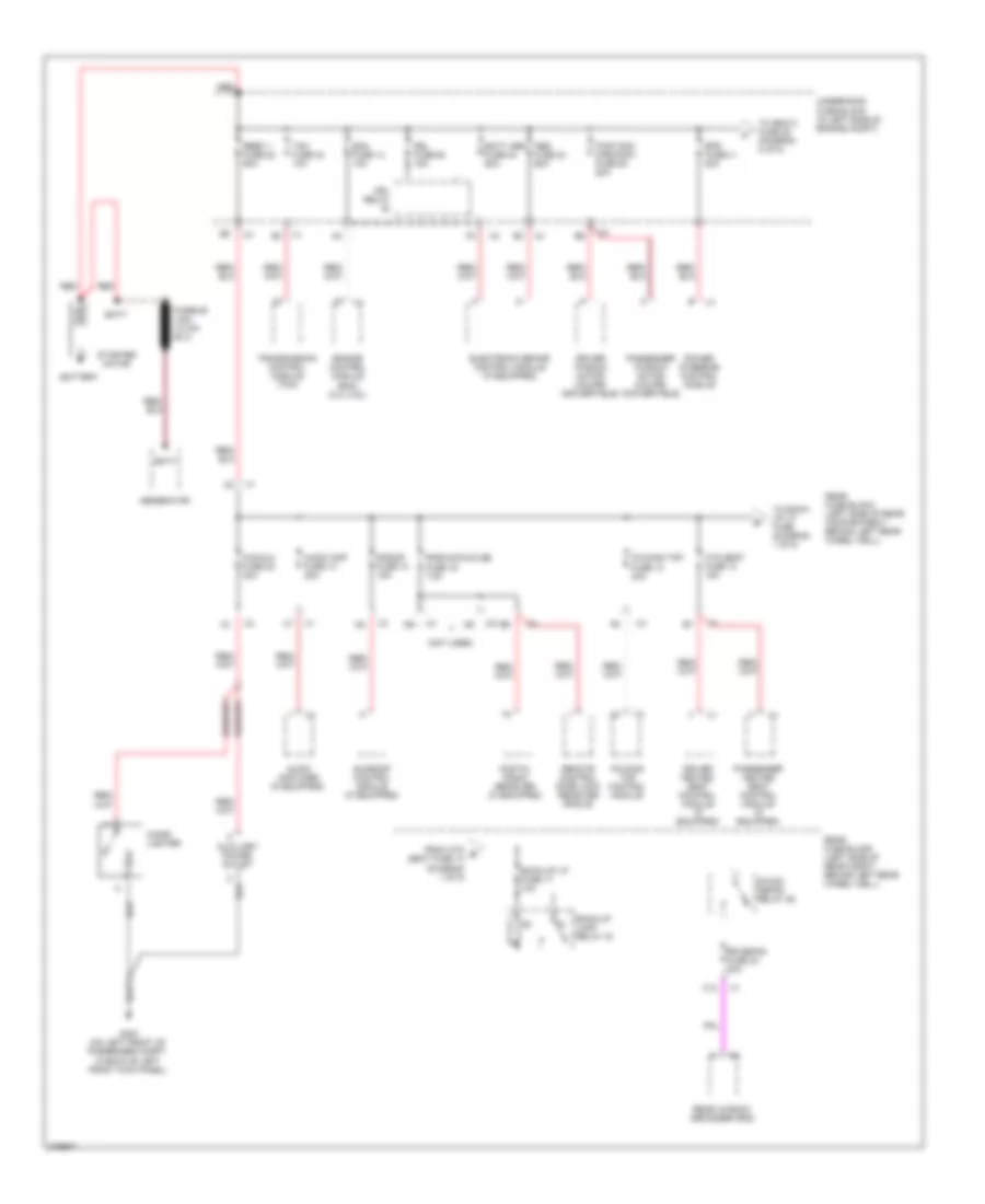 https://portal-diagnostov.com/license.html
Automotive Electricians Portal FZCO
Automotive Electricians Portal FZCO
https://portal-diagnostov.com/license.html
https://portal-diagnostov.com/license.html
Automotive Electricians Portal FZCO
Automotive Electricians Portal FZCOList of elements for Power Distribution Wiring Diagram (1 of 5) for Pontiac G6 2008:
- (not used)
- Abs fuse 24 60a
- Audio amp fuse 13 25a
- Audio amplifier (if equipped)
- Auxiliary power outlet
- Back-up lamp relay 33
- Back-up lp fuse 17 10a
- Batt
- Batt abs fuse 24 60a
- Battery
- C12
- Cig/aux fuse 20 20a
- Cigar lighter
- Digital radio receiver (if equipped)
- Driver heated seat control module (if equipped)
- Driver window motor (coupe/ convertible)
- Drl fuse 46 15a
- Drl relay
- Ecm fuse 13 10a
- Electronic brake control module (if equipped)
- Engine control module (ecm) (2.4l/3.6l)
- Eps fuse 41 80a
- Folding top control module
- Folding top fuse 12 20a
- From htd b seat fuse 14 (diagram 1 of 5)
- G303 (on left front of passenger compt, in back of left front kick panel)
- Generator
- Htd seat fuse 14 15a
- Passenger heated seat control module (if equipped)
- Passenger window motor (coupe/ convertible)
- Power steering control module
- Pwr wdo cpe/conv fuse 50 20a
- R/wdo defog relay 26
- Rbec 1 fuse 22 60a
- Rear fuse block (left side of rear compartment, behind left rear wheel well)
- Rear fuse block (left side of rear compt, behind left rear wheel well)
- Rear window defogger grid
- Red
- Remote control door lock receiver (rcdlr)
- Rke/xm/dvd/ugd fuse 16 7.5a
- Rr defog fuse 23 30a
- S/roof fuse 10 15a
- Starter motor
- Sunroof control module (if equipped)
- Tcm fuse 42 10a
- To back- up lp fuse (diagram 1 of 5)
- To ibcm 2 fuse 25 (diagram 2 of 5)
- Transmission control module (tcm)
- Underhood fuse block (in left side of engine compt)
Power Distribution Wiring Diagram (2 of 5) for Pontiac G6 2008
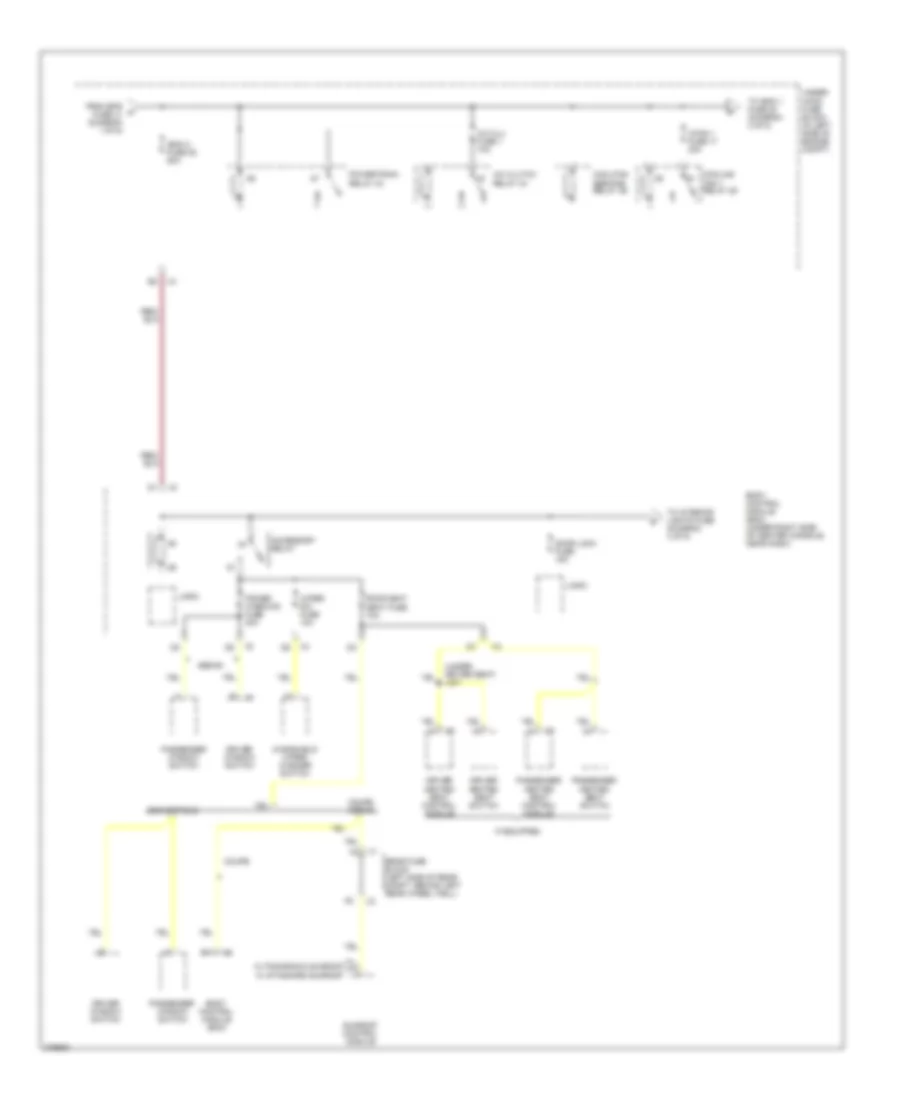 https://portal-diagnostov.com/license.html
Automotive Electricians Portal FZCO
Automotive Electricians Portal FZCO
https://portal-diagnostov.com/license.html
https://portal-diagnostov.com/license.html
Automotive Electricians Portal FZCO
Automotive Electricians Portal FZCOList of elements for Power Distribution Wiring Diagram (2 of 5) for Pontiac G6 2008:
- (under driver seat) j301
- A/c clu fuse 1 10a
- A/c clutch relay 34
- Accessory relay
- B11
- Body control module (bcm)
- Body control module (bcm) (under right side of center console, near dash)
- C/fan 1 fuse 17 30a
- Convertible
- Cool/fan ser/par relay 29
- Cooling fan 1 relay 28
- Coupe
- Coupe/ sedan
- Door lock fuse 15a
- Driver heated seat control module
- Driver heated seat switch
- Driver window switch
- From eps a fuse 41 (diagram 1 of 5)
- Ibcm 2 fuse 25 50a
- If equipped
- Logic
- Passenger heated seat control module
- Passenger heated seat switch
- Passenger window switch
- Power windows fuse 30a
- Powertrain relay 33
- Rear fuse block (left side of rear compt, behind left rear wheel well)
- Roof/heat seat fuse 10a
- Sedan
- Sunroof control module
- To ibcm 1 fuse 20 (diagram 3 of 5)
- To interior lights fuse (diagram 4 of 5)
- Under- hood fuse block (in left side of engine compt)
- W/ panoramic sunroof
- W/ standard sunroof
- Windshield wiper/ washer switch
- Wiper sw fuse 10a
Power Distribution Wiring Diagram (3 of 5) for Pontiac G6 2008
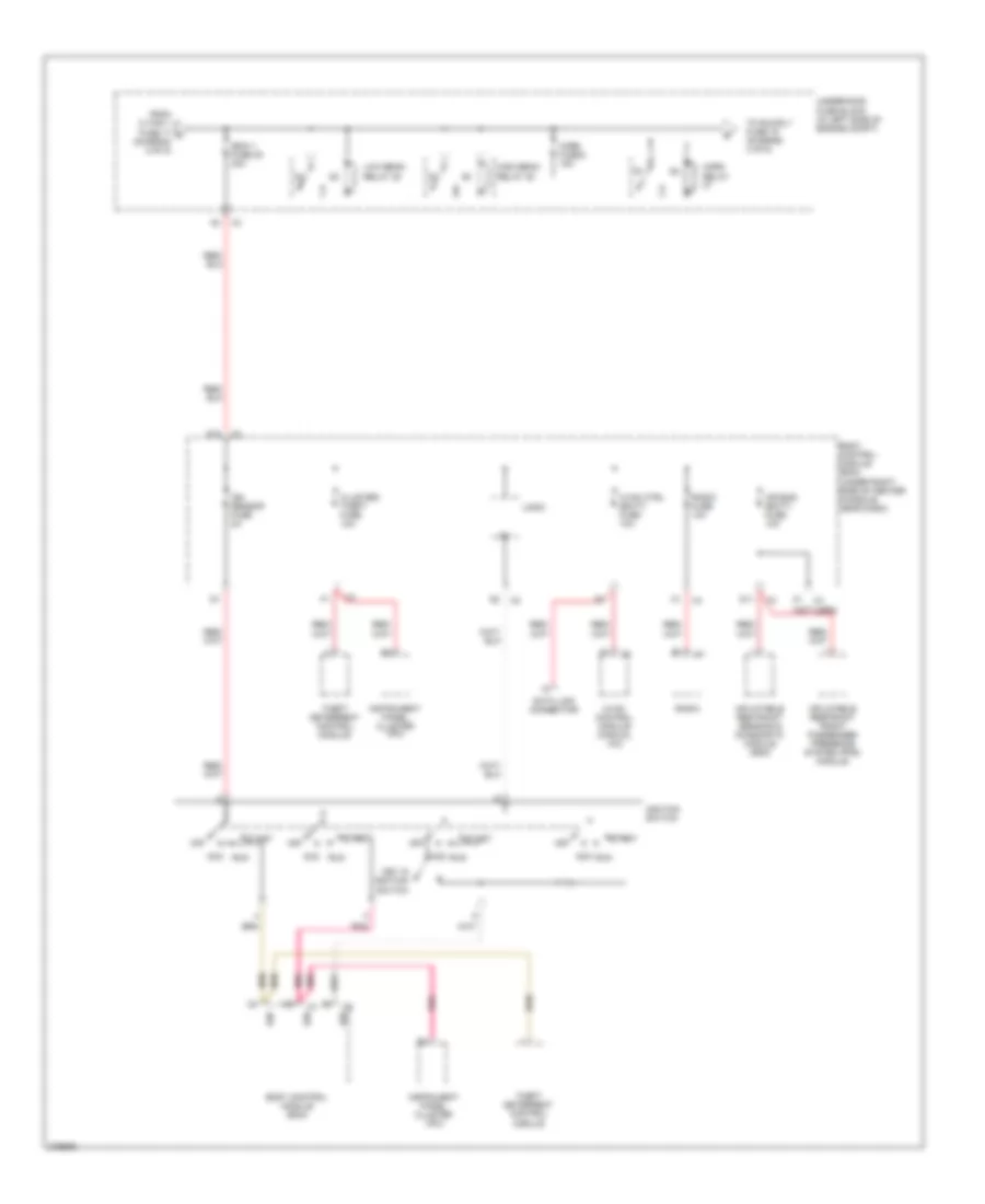 https://portal-diagnostov.com/license.html
Automotive Electricians Portal FZCO
Automotive Electricians Portal FZCO
https://portal-diagnostov.com/license.html
https://portal-diagnostov.com/license.html
Automotive Electricians Portal FZCO
Automotive Electricians Portal FZCOList of elements for Power Distribution Wiring Diagram (3 of 5) for Pontiac G6 2008:
- (not used)
- Acc run
- Air bag (batt) fuse 10a
- Body control module (bcm)
- Body control module (bcm) (under right side of center console, near dash)
- Cluster/ theft fuse 10a
- D11
- D12
- Data link connector
- From c/ fan 1 fuse 17 c (diagram 2 of 5)
- High beam relay 35
- Horn fuse 8 15a
- Horn relay
- Hvac control module (manual a/c)
- Hvac ctrl (batt) fuse 10a
- Ibcm 1 fuse 20 30a
- Ign
- Ign sensor fuse 2a
- Ignition switch
- Inflatable restraint front passenger presence system (pps) module
- Inflatable restraint sensing & diagnostic module (sdm)
- Instrument panel cluster (ipc)
- Key in ignition switch
- Logic
- Low beam relay 38
- Off
- Pnk
- Radio
- Radio fuse 10a
- Start
- Theft deterrent control module
- To run rly fuse 19 (diagram 4 of 5)
- Underhood fuse block (in left side of engine compt)
Power Distribution Wiring Diagram (4 of 5) for Pontiac G6 2008
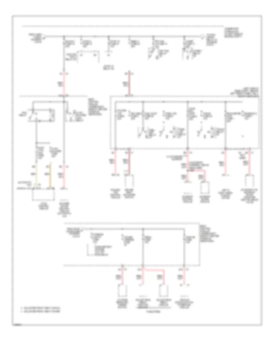 https://portal-diagnostov.com/license.html
Automotive Electricians Portal FZCO
Automotive Electricians Portal FZCO
https://portal-diagnostov.com/license.html
https://portal-diagnostov.com/license.html
Automotive Electricians Portal FZCO
Automotive Electricians Portal FZCOList of elements for Power Distribution Wiring Diagram (4 of 5) for Pontiac G6 2008:
- (automatic a/c)
- (in sunroof harness, above headliner) j405
- (left side of rear compt, behind left rear wheel well) rear fuse block
- (manual a/c)
- (not used)
- Adjustable pedal module
- Adjustable pedal position switch
- Adjuster front seat manual
- Adjuster front seat power
- Blower motor control module (automatic a/c)
- Body control module (under right side of center console, near dash)
- C/fan 2 fuse 18 30a
- Cooling fan 2 relay 30
- D10
- Driver seat adjuster switch
- Drv seat fuse 2 30a
- E10
- Emission 2 fuse 5 10a
- Evaporative emission (evap) canister vent solenoid valve
- Folding
- Folding top control module
- From door d locks fuse (diagram 2 of 5)
- From horn fuse 8 e (diagram 3 of 5)
- Frt fog lp fuse 10 15a
- Frt fog relay
- Fuel pump fuse 25 15a
- Fuel/ pmp relay
- Hvac blower fuse 20a
- Hvac blower high relay
- Hvac control module
- Hvac ctrl (ign) fuse 10a
- If equipped
- Inadvertent power outlet pcb relay
- Interior lights fuse 10a
- Left & right rear window motor
- Onstar fuse 10a
- Outside rearview mirror switch
- Park lps fuse 6 10a
- Park lps relay
- Pedal fuse 10a
- Power mirrors fuse 2a
- Rbec 2 fuse 23 60a
- Rr quarter wdo fuse 1 20a
- Run relay
- Run rly fuse 19 30a
- Sldg pnl roof fuse 9 25a
- Stop lp fuse 47 10a
- Stop lp relay 49
- Sunroof control module
- Sunroof shade module
- To run/ crank relay 32 (diagram 5 of 5)
- Top fuse 3 30a
- Trunk fuse 22 10a
- Trunk relay
- Underhood fuse block (in left side of engine compt)
- Vehicle communication interface module
- W/ standard sunroof
- Wiper 1 relay
- Wiper fuse 14 25a
Power Distribution Wiring Diagram (5 of 5) for Pontiac G6 2008
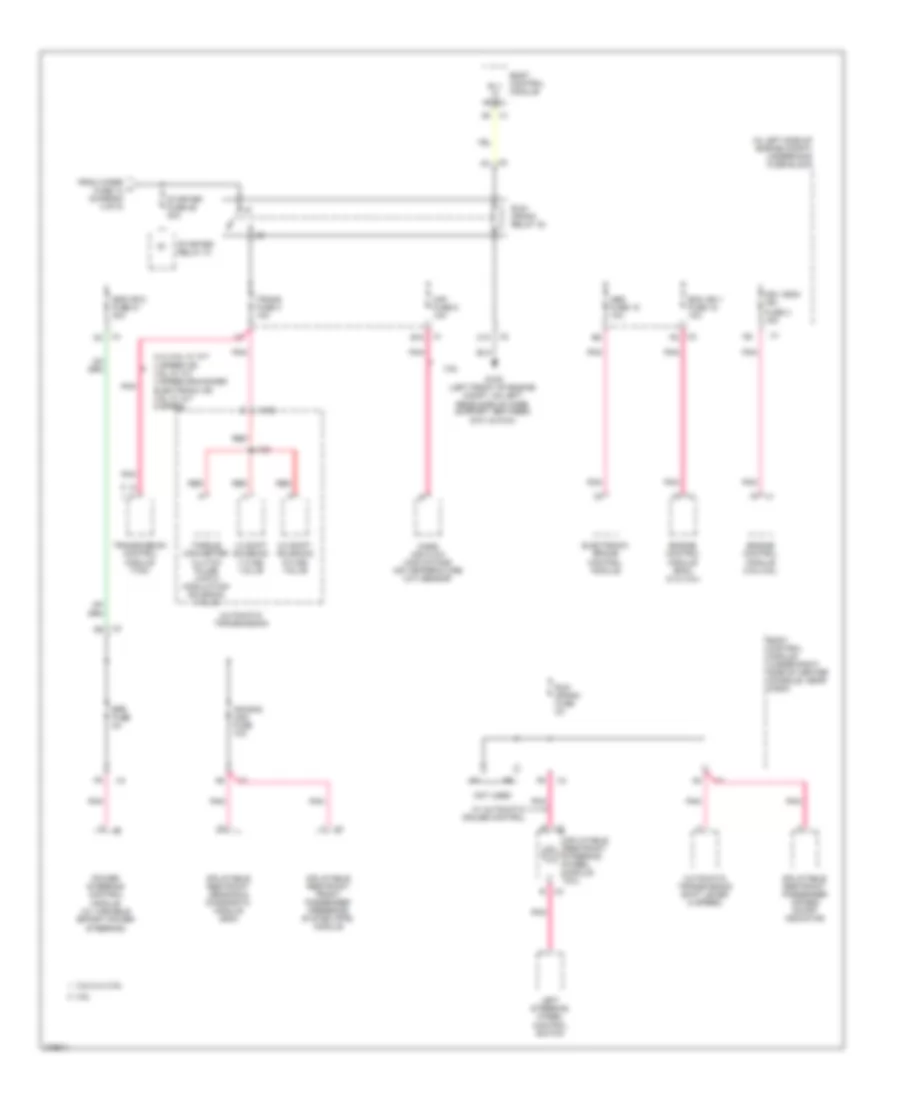 https://portal-diagnostov.com/license.html
Automotive Electricians Portal FZCO
Automotive Electricians Portal FZCO
https://portal-diagnostov.com/license.html
https://portal-diagnostov.com/license.html
Automotive Electricians Portal FZCO
Automotive Electricians Portal FZCOList of elements for Power Distribution Wiring Diagram (5 of 5) for Pontiac G6 2008:
- (in left side of engine compt) underhood fuse block
- 1-2 shift solenoid (1-2 ss) valve
- 2-3 shift solenoid (2-3 ss) valve
- 2.4l/3.5l w/ a/t 4 speed or 3.9l w/ a/t 4 speed enhanced electronic or 3.6l w/ a/t 6 speed
- 3.5l/2.4l/3.9l
- 3.6l
- Abs fuse 15 10a
- Air bag (ign) fuse 10a
- Automatic transmission
- Automatic transmission shift lever (4 speed)
- B10
- Body control module
- Body control module (under right side of center console, near dash)
- C10
- Ecm ign 1 fuse 16 10a
- Electronic brake control module
- Engine control module (3.5l/3.9l)
- Engine control module (ecm) (2.4l/3.5l)
- Eps fuse 2a
- From wiper fuse 14 (diagram 4 of 5)
- Fuse 3 15a
- G109 (left front of engine compt, on left rear side of core support, between g101 & g104)
- Ibcm (r/c) fuse 21 30a
- Ign 1/ecm ign
- Inflatable restraint front passenger presence system (pps) module
- Inflatable restraint passenger air bag on/off indicator
- Inflatable restraint sensing & diagnostic module (sdm)
- Inflatable restraint steering wheel module coil
- J103
- Left steering wheel control switch
- Maf fuse 5 10a
- Mass air flow (maf)/intake air temperature (iat) sensor
- Not used
- Pnk
- Power steering control module (w/ variable effort power steering)
- Red
- Rly hi ctrl
- Run crank fuse 2a
- Run/ crank relay 32
- Starter fuse 26 30a
- Starter relay 31
- Torque converter clutch pulse width modulation solenoid valve
- Trans fuse 4 10a
- Transmission control module (tcm)
- W/ automatic cruise control
- X100
POWER DOOR LOCKS
Power Door Locks Wiring Diagram for Pontiac G6 2008
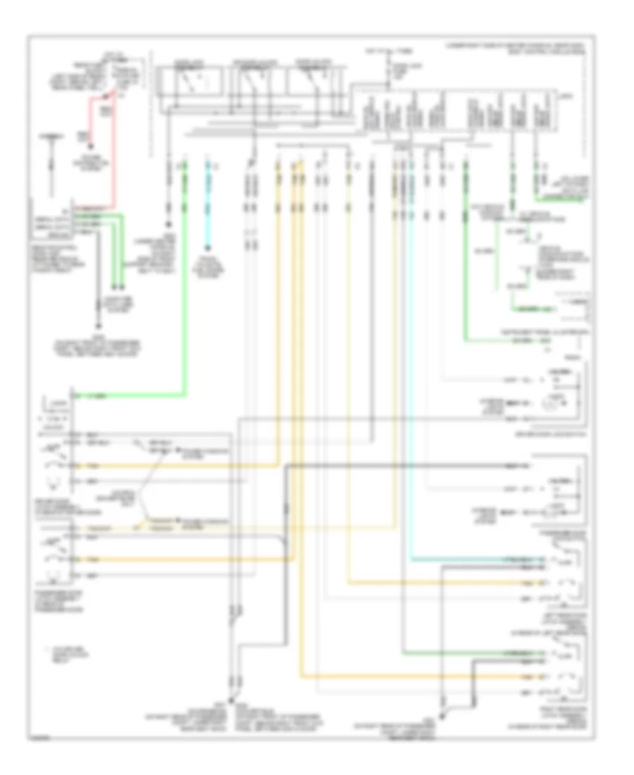 https://portal-diagnostov.com/license.html
Automotive Electricians Portal FZCO
Automotive Electricians Portal FZCO
https://portal-diagnostov.com/license.html
https://portal-diagnostov.com/license.html
Automotive Electricians Portal FZCO
Automotive Electricians Portal FZCOList of elements for Power Door Locks Wiring Diagram for Pontiac G6 2008:
- (on lower left of dash) data link connector (dlc)
- (under right side of center console, near dash) body control module (bcm)
- Ajar
- Ajar switch pass dr signal
- Antenna
- B10
- Computer data lines system
- Coupe & convertiblre only
- Door lock
- Door lock fuse 15a
- Door lock pcb relay
- Door unlock pcb relay
- Dr door unlock pcb relay
- Driver door latch assembly (in rear of driver door)
- Driver door lock switch
- Drvr dr ajar switch signal
- E12
- G203 (under center console, on right side of front support bracket, next to g201)
- G301 (coupe/sedan) (on right rear of passenger compt, under right rear seat back)
- G301 (on right rear of passenger compt, under right rear seat back)
- G305 (convertible) (on right front of passenger compt, behind right front kick panel, between g304 & door)
- G305 (on right front of passenger compt, behind right front kick panel, between g304 & door)
- Ground
- Hot at all times
- Instrument panel cluster (ipc)
- Interior lights system
- Left rear door latch assembly (sedan) (in rear of left rear door)
- Lock
- Logic
- Low spd gmlan
- Nca
- Passenger door latch assembly (in rear of passenger door)
- Passenger door lock switch
- Power distribution system
- Power windows system
- Radio
- Rear fuse block (left side of rear compt, behind left rear wheel well)
- Remote control door lock receiver (rcdlr) (attached to rear window shelf)
- Right rear door latch assembly (sedan) (in rear of right rear door)
- Rke/xm/ dvd/ugd fuse 16 7.5a
- Serial data
- Serial data gmlan low spd
- Signal key switch drvr dr
- Signal lck/unlck
- Tan
- Trunk rel relay control
- Trunk, tailgate, fuel doors system
- Unlock
- Vehicle communications interface module (vcim) (under right x4 side of dash)
- W/ vehicle communications
- W/o driver door unlock relay
- W/o vehicle communi- cations
POWER MIRRORS
Electrochromic Mirror Wiring Diagram, Convertible for Pontiac G6 2008
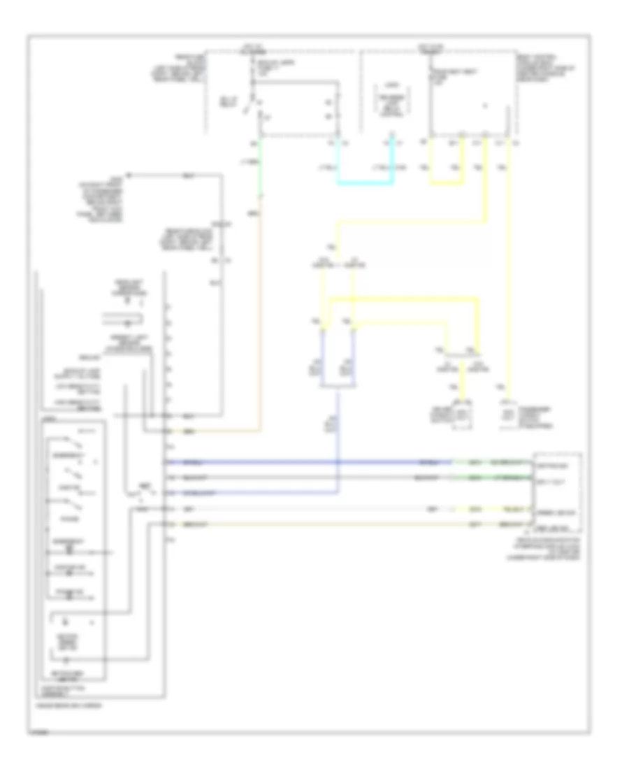 https://portal-diagnostov.com/license.html
Automotive Electricians Portal FZCO
Automotive Electricians Portal FZCO
https://portal-diagnostov.com/license.html
https://portal-diagnostov.com/license.html
Automotive Electricians Portal FZCO
Automotive Electricians Portal FZCOList of elements for Electrochromic Mirror Wiring Diagram, Convertible for Pontiac G6 2008:
- A11
- Acc volt
- Ambient light sensor (windshield side)
- B/u lp relay
- B11
- Bck/up lamps fuse 17 10a
- Body control module (bcm) (under right side of center console, near dash)
- C11
- Driver window switch
- E x1
- Emergency
- Emergency ind
- G305 (on right front of passenger compartment, behind right front kick panel, between g304 & door)
- Green led sig
- Ground
- Headlight sensor (mirror side)
- High sensitivity setting
- Hot at all times
- Hot in on or acc
- Inside rearview mirror
- Keypad green led ind
- Keypad red led ind
- Keypad sig
- Logic
- Low sensitivity setting
- Max
- Min
- Off
- Onstar
- Onstar button assembly
- Onstar ind
- Passenger window switch (if equipped)
- Phone
- Phone ind
- Rear fuse block (left side of rear compt, behind left rear wheel well)
- Red led sig
- Reverse lamp relay control
- Roof/heat seat fuse 10a
- Sply volt
- Vehicle communication interface module (vcim) (w/ onstar) (under right side of dash)
- W/ onstar
- W/o onstar
- X3 b2
Electrochromic Mirror Wiring Diagram, Except Convertible for Pontiac G6 2008
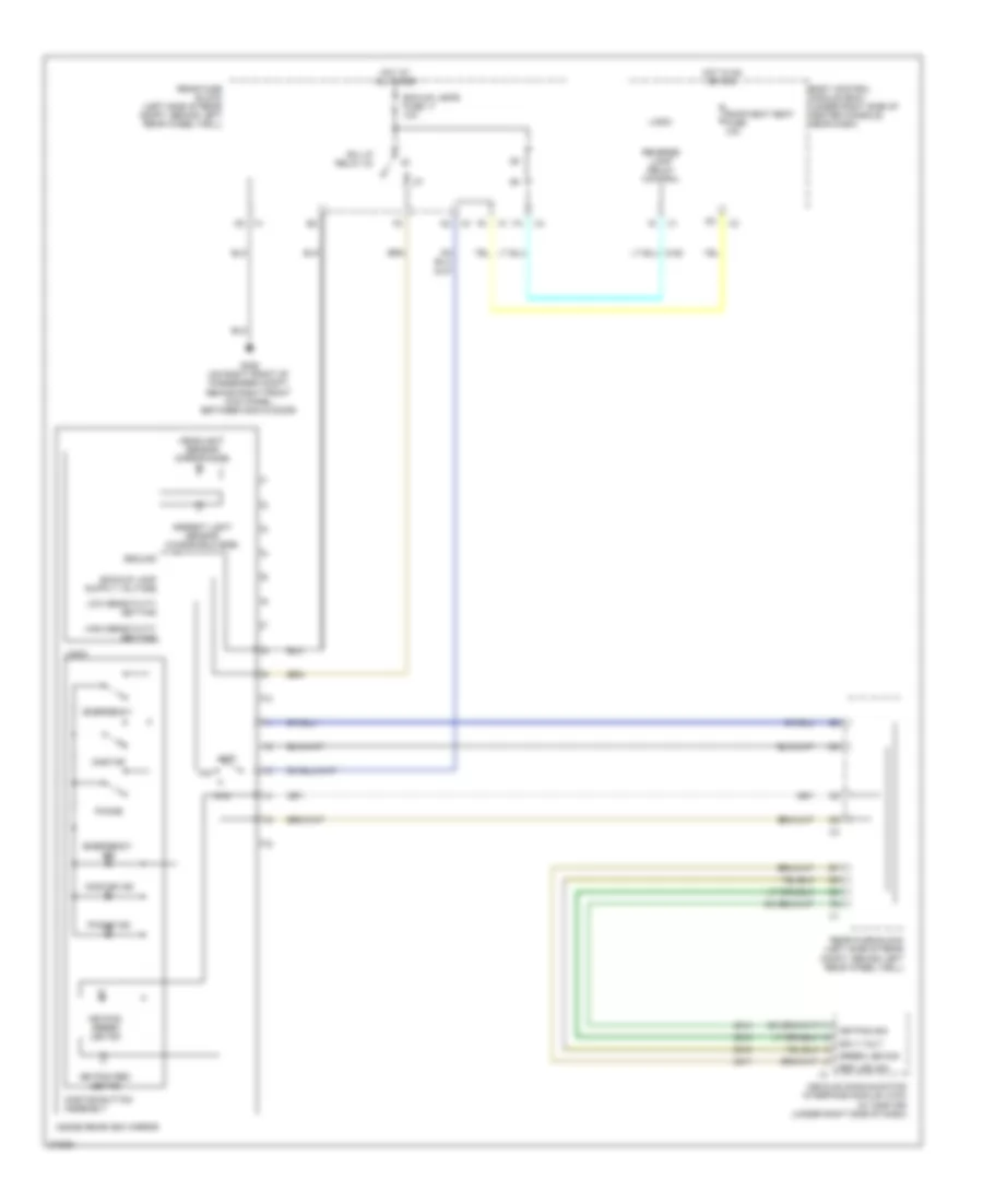 https://portal-diagnostov.com/license.html
Automotive Electricians Portal FZCO
Automotive Electricians Portal FZCO
https://portal-diagnostov.com/license.html
https://portal-diagnostov.com/license.html
Automotive Electricians Portal FZCO
Automotive Electricians Portal FZCOList of elements for Electrochromic Mirror Wiring Diagram, Except Convertible for Pontiac G6 2008:
- Ambient light sensor (windshield side)
- B/u lp relay 33
- Bck/up lamps fuse 17 10a
- Body control module (bcm) (under right side of center console, near dash)
- Emergency
- Emergency ind
- G305 (on right front of passenger compt, behind right front kick panel, between g304 & door)
- Green led sig
- Ground
- Headlight sensor (mirror side)
- High sensitivity setting
- Hot at all times
- Hot in on or acc
- Inside rearview mirror
- Keypad green led ind
- Keypad red led ind
- Keypad sig
- Logic
- Low sensitivity setting
- Max
- Min
- Off
- Onstar
- Onstar button assembly
- Onstar ind
- Phone
- Phone ind
- Rear fuse block (left side of rear compt, behind left rear wheel well)
- Red led sig
- Reverse lamp relay control
- Roof/heat seat fuse 10a
- Sply volt
- Vehicle communication interface module (vcim) (w/ onstar) (under right side of dash)
Power Mirrors Wiring Diagram for Pontiac G6 2008
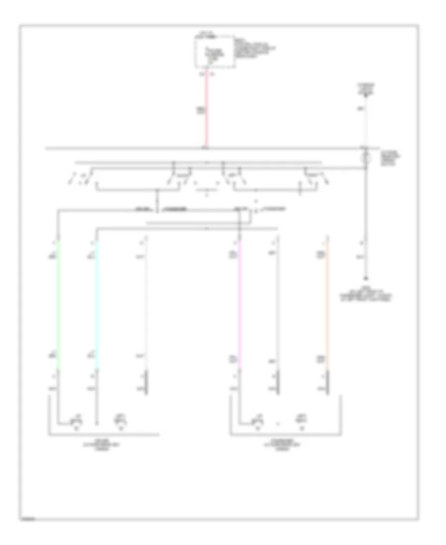 https://portal-diagnostov.com/license.html
Automotive Electricians Portal FZCO
Automotive Electricians Portal FZCO
https://portal-diagnostov.com/license.html
https://portal-diagnostov.com/license.html
Automotive Electricians Portal FZCO
Automotive Electricians Portal FZCOList of elements for Power Mirrors Wiring Diagram for Pontiac G6 2008:
- (on left front of passenger compt, in back of left front kick panel)
- Body control module (under right side of center console, near dash)
- Down
- Driver
- Driver outside rearview mirror
- G303
- Hot at all times
- Interior lights system
- Left
- Left/ right
- Nca
- Outside rearview mirror switch
- Passenger
- Passenger outside rearview mirror
- Power mirrors fuse 2a
- Right
- Up/ down
POWER SEATS
2-Way Adjustable Power Seat Wiring Diagram for Pontiac G6 2008
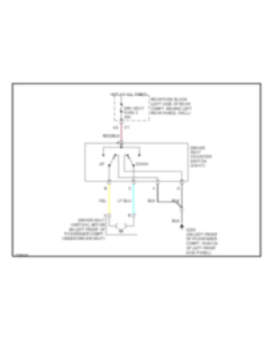 https://portal-diagnostov.com/license.html
Automotive Electricians Portal FZCO
Automotive Electricians Portal FZCO
https://portal-diagnostov.com/license.html
https://portal-diagnostov.com/license.html
Automotive Electricians Portal FZCO
Automotive Electricians Portal FZCOList of elements for 2-Way Adjustable Power Seat Wiring Diagram for Pontiac G6 2008:
- Down
- Driver seat adjuster switch (2-way)
- Driver seat vertical motor (in left front of passenger compt, under driver seat)
- Drv seat fuse 2 30a
- G303 (on left front of passenger compt, in back of left front kick panel)
- Hot at all times
- Rear fuse block (left side of rear compt, behind left rear wheel well)
6-Way Power Seat Wiring Diagram for Pontiac G6 2008
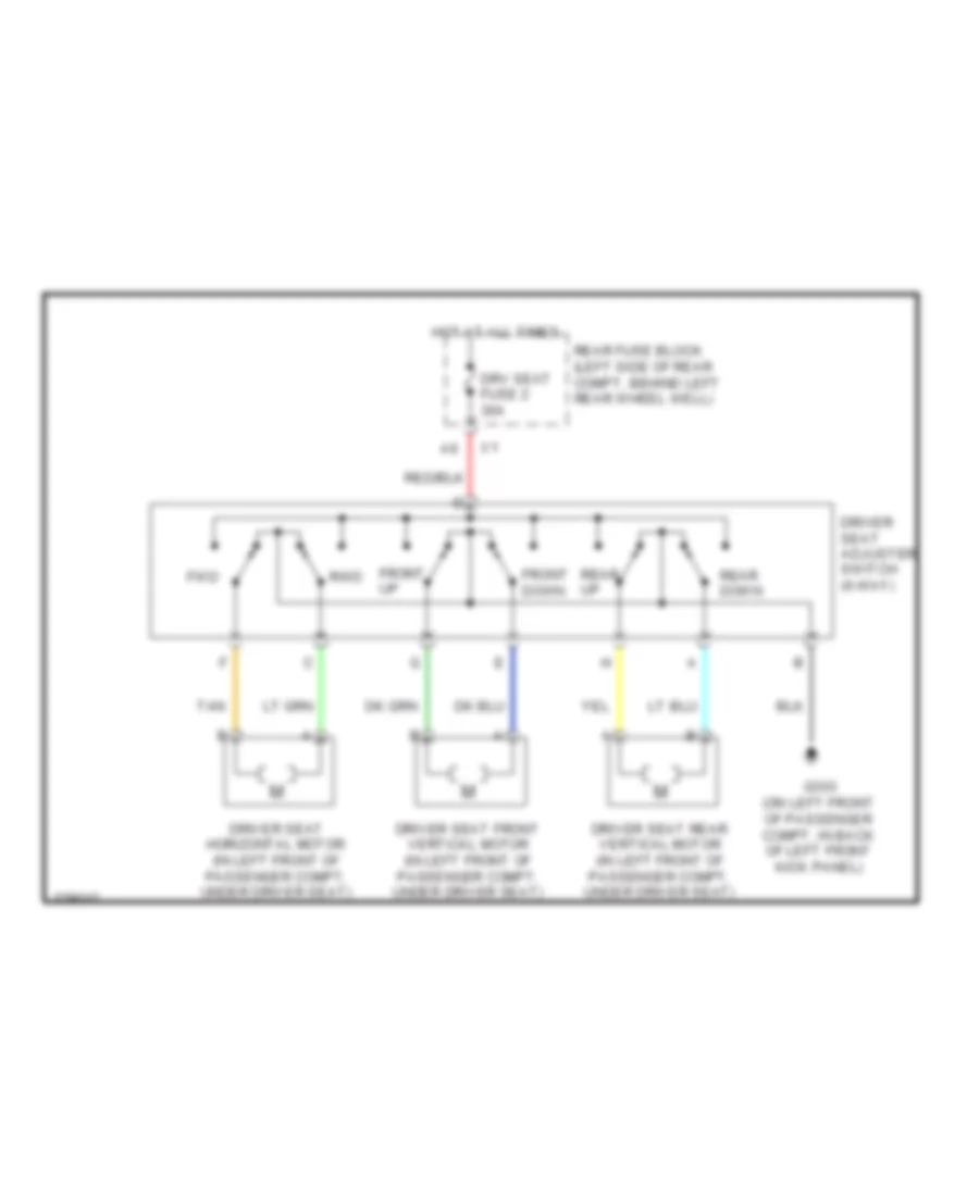 https://portal-diagnostov.com/license.html
Automotive Electricians Portal FZCO
Automotive Electricians Portal FZCO
https://portal-diagnostov.com/license.html
https://portal-diagnostov.com/license.html
Automotive Electricians Portal FZCO
Automotive Electricians Portal FZCOList of elements for 6-Way Power Seat Wiring Diagram for Pontiac G6 2008:
- Driver seat adjuster switch (6-way)
- Driver seat front vertical motor (in left front of passenger compt, under driver seat)
- Driver seat horizontal motor (in left front of passenger compt, under driver seat)
- Driver seat rear vertical motor (in left front of passenger compt, under driver seat)
- Drv seat fuse 2 30a
- Front down
- Front up
- Fwd
- G303 (on left front of passenger compt, in back of left front kick panel)
- Hot at all times
- Rear down
- Rear fuse block (left side of rear compt, behind left rear wheel well)
- Rear up
- Rwd
- Tan
Adjustable Pedal Wiring Diagram for Pontiac G6 2008
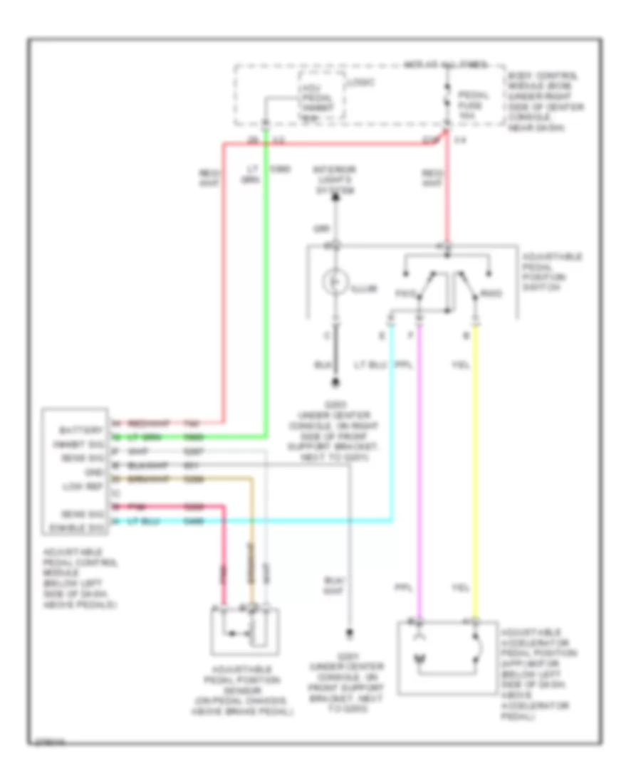 https://portal-diagnostov.com/license.html
Automotive Electricians Portal FZCO
Automotive Electricians Portal FZCO
https://portal-diagnostov.com/license.html
https://portal-diagnostov.com/license.html
Automotive Electricians Portal FZCO
Automotive Electricians Portal FZCOList of elements for Adjustable Pedal Wiring Diagram for Pontiac G6 2008:
- Adj pedal inhibit sw
- Adjustable accelerator pedal position (app) motor (below left side of dash, above accelerator pedal)
- Adjustable pedal control module (below left side of dash, above pedals)
- Adjustable pedal position sensor (on pedal chassis, above brake pedal)
- Adjustable pedal position switch
- Battery
- Body control module (bcm) (under right side of center console, near dash)
- D10
- Enable sig
- Fwd
- G201 (under center console, on front support bracket, next to g203)
- G203 under center console, on right side of front support bracket, next to g201)
- Gnd
- Hot at all times
- Illum
- Inhibit sig
- Interior lights system
- Logic
- Low ref
- Pedal fuse 10a
- Pnk
- Rwd
- Sens sig
Heated Seats Wiring Diagram for Pontiac G6 2008
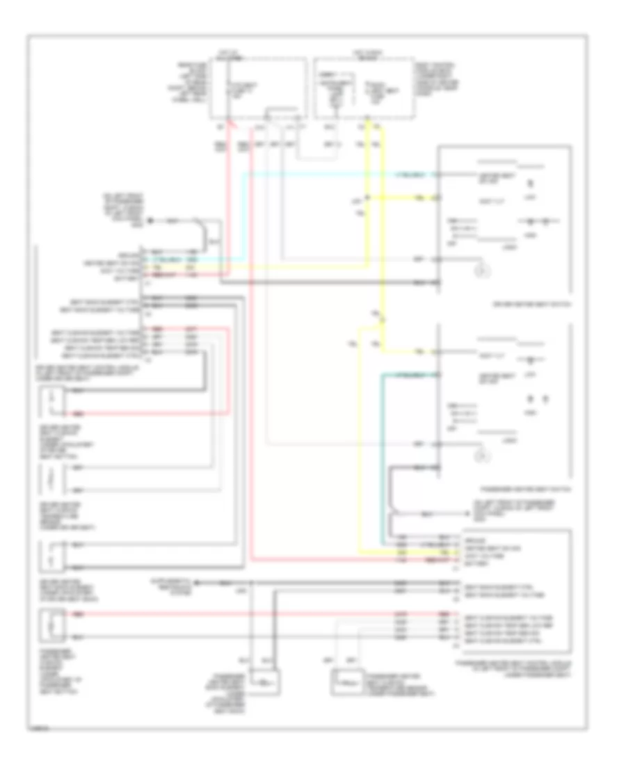 https://portal-diagnostov.com/license.html
Automotive Electricians Portal FZCO
Automotive Electricians Portal FZCO
https://portal-diagnostov.com/license.html
https://portal-diagnostov.com/license.html
Automotive Electricians Portal FZCO
Automotive Electricians Portal FZCOList of elements for Heated Seats Wiring Diagram for Pontiac G6 2008:
- (on left front of passenger compt, in back of left front kick panel) g303
- Accy vlt
- Accy voltage
- B12
- Battery
- Body control module (bcm) (under right side of center console, near dash)
- D10
- Driver heated seat back element (under upholstery of driver seat back)
- Driver heated seat control module (in left front of passenger compt, under driver seat)
- Driver heated seat cushion element (under upholstery of driver seat bottom)
- Driver heated seat cushion temperature sensor (under driver seat)
- Driver heated seat switch
- Ground
- Heated seat sw sig
- High
- Hot at all times
- Hot in run or acc
- Htd seat fuse 14 15a
- Instrument panel lamp sply volt
- J301
- J305
- Logic
- Low
- Off
- Passenger heated seat back element (under upholstery of passenger seat back)
- Passenger heated seat control module (in left front of passenger compt, under passenger seat)
- Passenger heated seat cushion element (under upholstery of passenger seat bottom)
- Passenger heated seat cushion temperature sensor (under passenger seat)
- Passenger heated seat switch
- Rear fuse block (left side of rear compt, behind left rear wheel well)
- Red
- Roof/ heat seat fuse 10a
- Seat back element ctrl
- Seat back element voltage
- Seat cushion element ctrl
- Seat cushion element voltage
- Seat cushion temp sen low ref
- Seat cushion temp sen sig
- X1 f11
POWER TOP/SUNROOF
Convertible Top Wiring Diagram (1 of 2) for Pontiac G6 2008
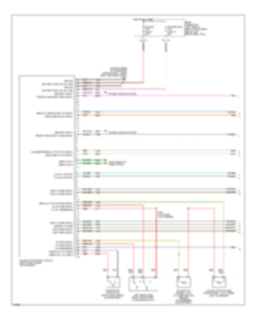 https://portal-diagnostov.com/license.html
Automotive Electricians Portal FZCO
Automotive Electricians Portal FZCO
https://portal-diagnostov.com/license.html
https://portal-diagnostov.com/license.html
Automotive Electricians Portal FZCO
Automotive Electricians Portal FZCOList of elements for Convertible Top Wiring Diagram (1 of 2) for Pontiac G6 2008:
- (on right rear of passenger compartment, under right rear seat back) g301
- 12 volt reference
- Battery positive voltage
- Computer data lines system
- Convertible top fuse 12 20a
- Decklid hinge dowel pin signal
- Decklid latch extend signal
- Direction voltage a
- Direction voltage b
- Extend signal
- Folding top control module (right side of rear compartment)
- Folding top fuse 3 30a
- Folding top header latch cylinder position sensor (in passenger compartment)
- Folding top pump motor (right side of rear compartment)
- Folding top stowage compartment lid cylinder position sensor
- Ground
- Header latched
- Headliner dowel signal
- Headliner latch signal
- Hot at all times
- J402 (in folding top harness)
- Latched signal
- Left rear hinge rear compartment lid release switch
- Low reference
- Luggage barrier limit switch signal
- Power windows system
- Rear fuse block (left side of rear compartment, behind left rear wheel well)
- Red
- Request signal
- Retractable roof close signal
- Retractable roof open signal
- Roof closed signal
- Roof locked signal
- Roof open signal
- Serial data
- Unlatched signal
- Valve 1 control
- Valve 2 control
Convertible Top Wiring Diagram (2 of 2) for Pontiac G6 2008
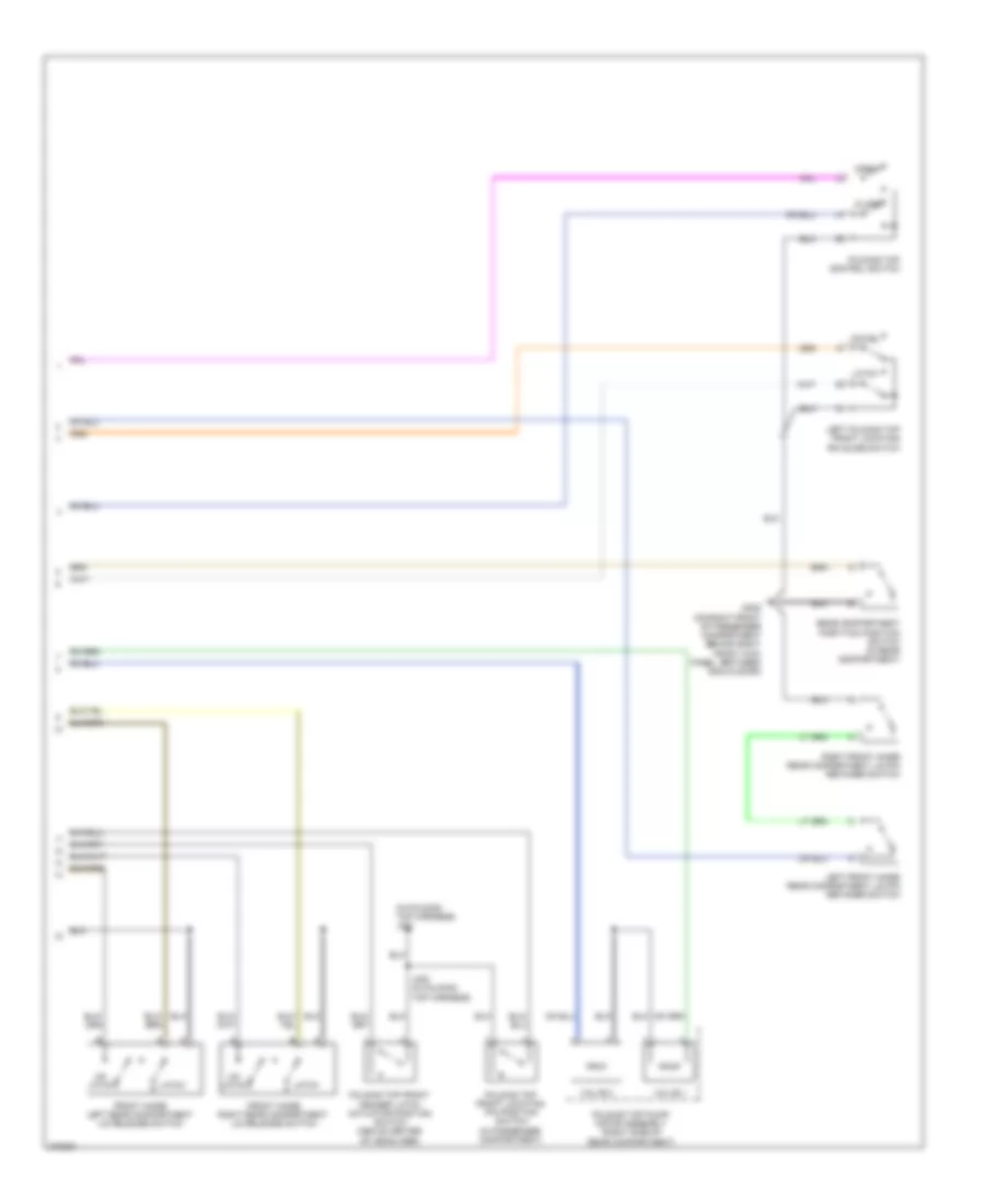 https://portal-diagnostov.com/license.html
Automotive Electricians Portal FZCO
Automotive Electricians Portal FZCO
https://portal-diagnostov.com/license.html
https://portal-diagnostov.com/license.html
Automotive Electricians Portal FZCO
Automotive Electricians Portal FZCOList of elements for Convertible Top Wiring Diagram (2 of 2) for Pontiac G6 2008:
- (in folding top harness) j401
- Close
- Dowel
- Folding top control switch
- Folding top front header latch actuator position switch (above center of headliner)
- Folding top front locating pin position switch (in passenger compartment)
- Folding top pump/ motor assembly (right side of rear compartment)
- Front hinge left rear compartment lid release switch
- Front hinge right rear compartment lid release switch
- G305 (on right front of passenger compartment behind right front kick panel, between g304 & door)
- J400 (in folding top harness)
- Latch
- Left folding top front locating pin guide switch
- Left front hinge rear compartment lid pin retainer switch
- Open
- Rear compartment partition position switch (in rear compartment)
- Right front hinge rear compartment lid pin retainer switch
- Un- latch
- Valve 1
- Valve 2
Panoramic Roof Wiring Diagram for Pontiac G6 2008
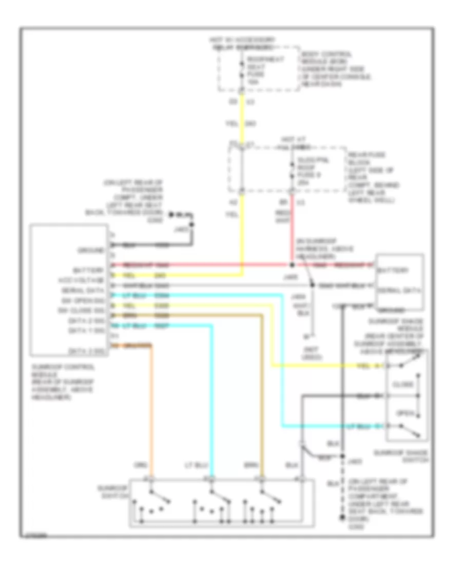 https://portal-diagnostov.com/license.html
Automotive Electricians Portal FZCO
Automotive Electricians Portal FZCO
https://portal-diagnostov.com/license.html
https://portal-diagnostov.com/license.html
Automotive Electricians Portal FZCO
Automotive Electricians Portal FZCOList of elements for Panoramic Roof Wiring Diagram for Pontiac G6 2008:
- (in sunroof harness, above headliner)
- (not used)
- (on left rear of passenger compartment, under left rear seat back, towards door) g302
- (on left rear of passenger compt, under left rear seat back, towards door) g302
- Acc voltage
- Battery
- Body control module (bcm) (under right side of center console, near dash)
- Close
- Data 1 sig
- Data 2 sig
- Data 3 sig
- Ground
- Hot at all times
- Hot w/ accessory relay energized
- J403
- J404
- J405
- Open
- Rear fuse block (left side of rear compt, behind left rear wheel well)
- Roof/heat seat fuse 10a
- Serial data
- Sldg pnl roof fuse 9 25a
- Sunroof control module (rear of sunroof assembly, above headliner)
- Sunroof shade module (rear center of sunroof assembly, above headliner)
- Sunroof shade switch
- Sunroof switch
- Sw close sig
- Sw open sig
Sunroof Wiring Diagram for Pontiac G6 2008
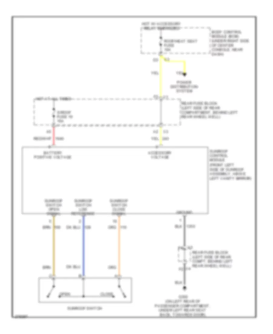 https://portal-diagnostov.com/license.html
Automotive Electricians Portal FZCO
Automotive Electricians Portal FZCO
https://portal-diagnostov.com/license.html
https://portal-diagnostov.com/license.html
Automotive Electricians Portal FZCO
Automotive Electricians Portal FZCOList of elements for Sunroof Wiring Diagram for Pontiac G6 2008:
- (front left side of sunroof assembly, above left vanity mirror)
- Accessory voltage
- Battery positive voltage
- Body control module (bcm) (under right side of center console, near dash)
- Close
- G302 (on left rear of passenger compartment, under left rear seat back, towards door)
- Ground
- Hot at all times
- Hot w/ accessory relay energized
- Open
- Power distribution system
- Rear fuse block (left side of rear compartment, behind left rear wheel well)
- Rear fuse block (left side of rear compt, behind left rear wheel well)
- Roof/heat seat fuse 10a
- S/roof fuse 10 15a
- Sunroof control module
- Sunroof switch
- Sunroof switch close signal
- Sunroof switch low reference
- Sunroof switch open signal
- X4 f2
POWER WINDOWS
Power Windows Wiring Diagram, Convertible (1 of 2) for Pontiac G6 2008
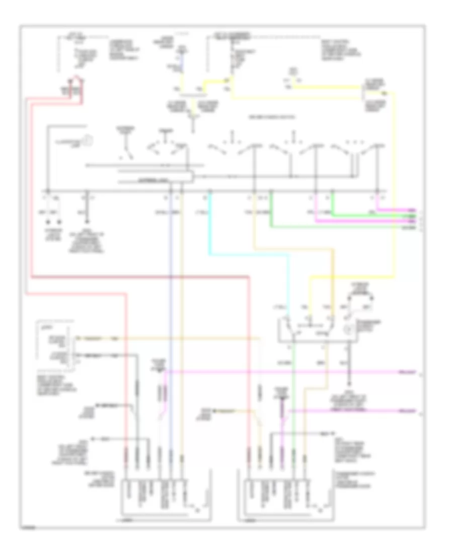 https://portal-diagnostov.com/license.html
Automotive Electricians Portal FZCO
Automotive Electricians Portal FZCO
https://portal-diagnostov.com/license.html
https://portal-diagnostov.com/license.html
Automotive Electricians Portal FZCO
Automotive Electricians Portal FZCOList of elements for Power Windows Wiring Diagram, Convertible (1 of 2) for Pontiac G6 2008:
- (center of passenger door)
- Acc volt
- Battery
- Body control module (bcm) (under right side of center console, near dash)
- Door locks system
- Down
- Driver
- Driver window motor (center of driver door)
- Driver window switch
- Express down
- Express logic
- G301 (on right rear of passenger compartment, under right rear seat back)
- G303 (on left front of passenger compartment, in back of left front kick panel)
- G303 (on left front of passenger compt, in back of left front kick panel)
- Ground
- Hard top req retractable
- Hot at all times
- Hot w/ accessory relay energized
- Illumination lamp
- Inside rearview mirror
- Interior lights system
- Lf door ajar sw sig
- Lf door ajar sw signal
- Lf down ctrl
- Lf up ctrl
- Logic
- Passenger window motor
- Passenger window switch
- Power tops system
- Pwr wdo cpe/conv fuse 50 20a
- Retractable hard top req
- Rf door ajar sw sig
- Rf down ctrl
- Rf up ctrl
- Roof/heat seat fuse 10a
- Sw signal rf door ajar
- Tan
- Underhood fuse block (in left side of engine compartment)
- W/ inside rearview mirror
- W/o inside rearview mirror
- X11
Power Windows Wiring Diagram, Convertible (2 of 2) for Pontiac G6 2008
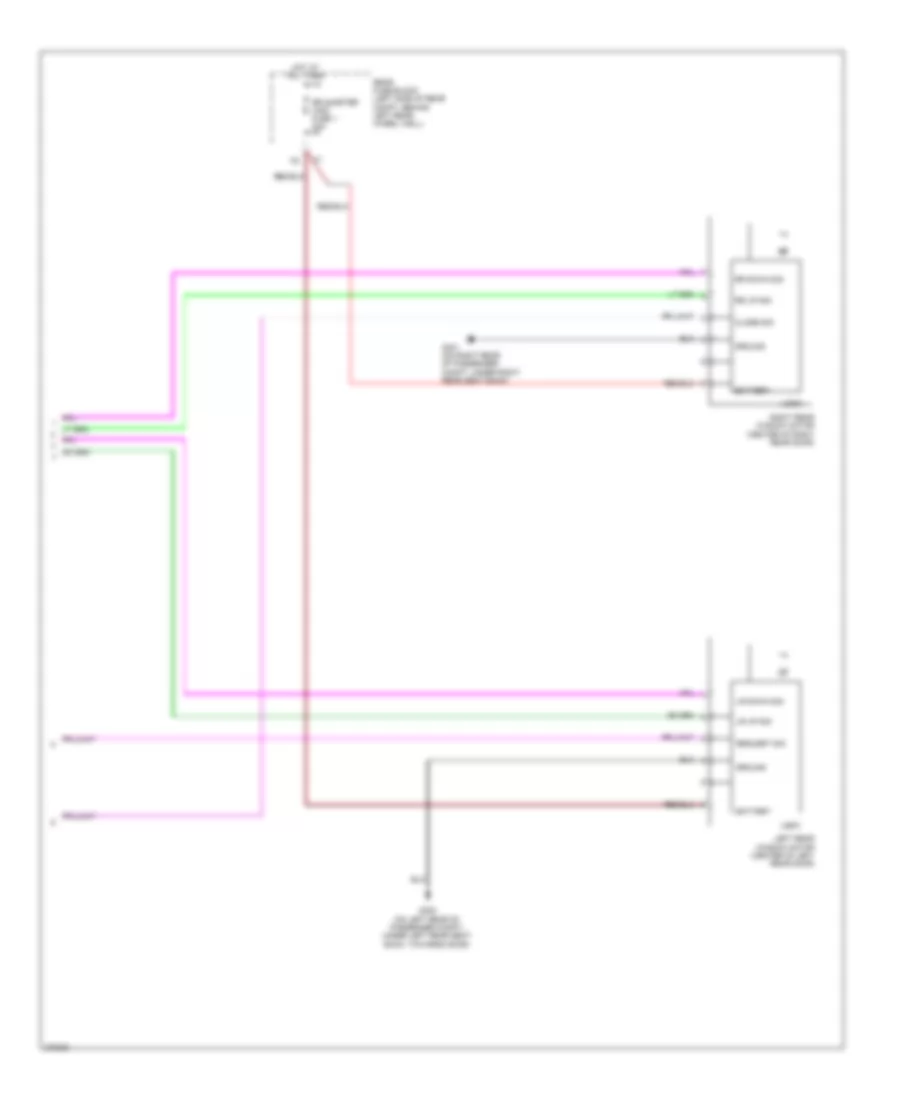 https://portal-diagnostov.com/license.html
Automotive Electricians Portal FZCO
Automotive Electricians Portal FZCO
https://portal-diagnostov.com/license.html
https://portal-diagnostov.com/license.html
Automotive Electricians Portal FZCO
Automotive Electricians Portal FZCOList of elements for Power Windows Wiring Diagram, Convertible (2 of 2) for Pontiac G6 2008:
- Battery
- Close sig
- G301 (on right rear of passenger compt, under right rear seat back)
- G302 (on left rear of passenger compt, under left rear seat back, towards door)
- Ground
- Hot at all times
- Left rear window motor (center of left rear door)
- Logic
- Lr down sig
- Lr up sig
- Rear fuse block (left side of rear compt, behind left rear wheel well)
- Request sig
- Right rear window motor (center of right rear door)
- Rr down sig
- Rr quarter wdo fuse 1 20a
- Rr up sig
Power Windows Wiring Diagram, Coupe for Pontiac G6 2008
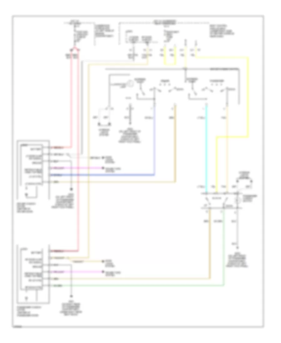 https://portal-diagnostov.com/license.html
Automotive Electricians Portal FZCO
Automotive Electricians Portal FZCO
https://portal-diagnostov.com/license.html
https://portal-diagnostov.com/license.html
Automotive Electricians Portal FZCO
Automotive Electricians Portal FZCOList of elements for Power Windows Wiring Diagram, Coupe for Pontiac G6 2008:
- (center of passenger door)
- A11
- B11
- Battery
- Body control module (bcm) (under right side of center console, near dash)
- C11
- Door locks system
- Down
- Driver
- Driver window motor (center of driver door)
- Driver window switch
- Express down
- G301 (on right rear of passenger compartment, under right rear seat back)
- G303 (on left front of passenger compartment, in back of left front kick panel)
- Ground
- Hot at all times
- Hot w/ accessory relay energized
- Illumination lamp
- Interior lights system
- Lf door ajar sw sig
- Lf door ajar sw signal
- Lf down ctrl
- Lf up ctrl
- Logic
- Passenger
- Passenger window motor
- Passenger window switch
- Power tops system
- Pwr wdo cpe/conv fuse 50 20a
- Retractable hard top req
- Rf door ajar sw sig
- Rf door ajar sw signal
- Rf down ctrl
- Rf up ctrl
- Roof/heat seat fuse 10a
- Tan
- Underhood fuse block (in left side of engine compartment)
Power Windows Wiring Diagram, Sedan for Pontiac G6 2008
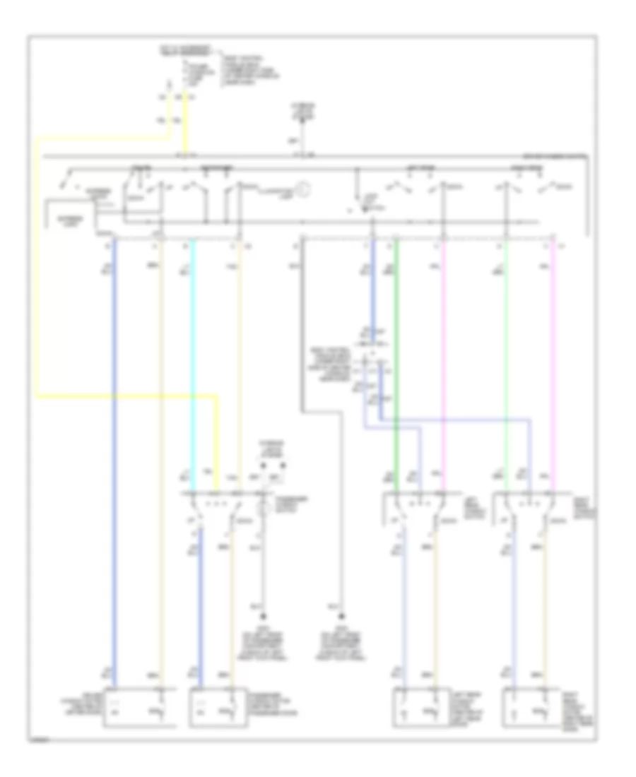 https://portal-diagnostov.com/license.html
Automotive Electricians Portal FZCO
Automotive Electricians Portal FZCO
https://portal-diagnostov.com/license.html
https://portal-diagnostov.com/license.html
Automotive Electricians Portal FZCO
Automotive Electricians Portal FZCOList of elements for Power Windows Wiring Diagram, Sedan for Pontiac G6 2008:
- A11
- B11
- Body control module (bcm) (under right side of center console, near dash)
- C11
- Down
- Driver
- Driver window motor (center of driver door)
- Driver window switch
- Ecb
- Express down
- Express logic
- G303 (on left front of passenger compartment, in back of left front kick panel)
- Hot w/ accessory relay energized
- Illumination lamp
- Interior lights system
- Left rear
- Left rear window motor (center of left rear door)
- Left rear window switch
- Lock out switch
- Passenger
- Passenger window motor (center of passenger door)
- Passenger window switch
- Power windows fuse 30a
- Right rear
- Right rear window motor (center of right rear door)
- Right rear window switch
- Tan
RADIO
6-Speaker System Wiring Diagram for Pontiac G6 2008
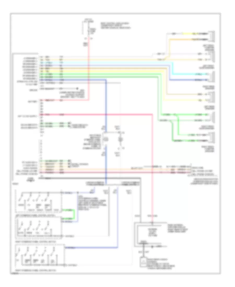 https://portal-diagnostov.com/license.html
Automotive Electricians Portal FZCO
Automotive Electricians Portal FZCO
https://portal-diagnostov.com/license.html
https://portal-diagnostov.com/license.html
Automotive Electricians Portal FZCO
Automotive Electricians Portal FZCOList of elements for 6-Speaker System Wiring Diagram for Pontiac G6 2008:
- 1-6
- 10 volt ref
- 3 spoke steering wheel controls
- 4 spoke steering wheel controls
- A10
- A11
- A12
- Audio common
- B tan
- B10
- B11
- B12
- Band
- Bare
- Battery
- Body control module (bcm) (under right side of center console, near dash)
- Case ground
- Cell phone low ref
- Cell phone voice sig
- Coax
- Computer data lines system
- Drain wire
- G201 (under center console, on front support bracket, next to g203)
- Gmlan ser data
- Ground
- Hot at all times
- Inflatable restraint steering wheel module coil (behind steering wheel, in steering column)
- J203 (in steering wheel controls harness, under left side of inflatable restraint steering wheel module, 11 cm (4.4 in) from x276)
- Left front door speaker
- Left front tweeter speaker
- Left rear speaker
- Left steering wheel control switch
- Lf speaker (+)
- Lf speaker (-)
- Logic
- Lr speaker (+)
- Lr speaker (-)
- Lt audio sig (+)
- Mute
- Nca
- Pnk
- Radio
- Radio antenna
- Radio antenna amplifier module (right rear of roof under headliner)
- Radio fuse 10a
- Radio rear window antenna (attached to top of rear window, above rear window defogger grid)
- Rf speaker (+)
- Rf speaker (-)
- Right front door speaker
- Right front tweeter speaker
- Right rear speaker
- Right steering wheel control switch
- Rr speaker (+)
- Rr speaker (-)
- Rt audio sig (+)
- Satellite radio circuit
- Seek
- Seek dn
- Seek up
- Srce
- Strng whl ctrl sig
- Tan
- Vehicle communication interface module (vcim) (under right side of dash)
- Vol +
- Vol -
- Vol dn -
- Vol up +
8-Speaker System Wiring Diagram, Convertible (1 of 2) for Pontiac G6 2008
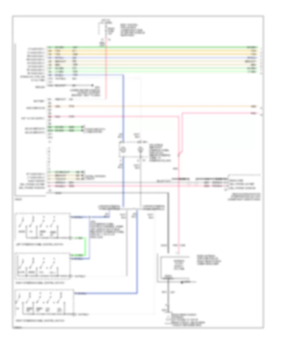 https://portal-diagnostov.com/license.html
Automotive Electricians Portal FZCO
Automotive Electricians Portal FZCO
https://portal-diagnostov.com/license.html
https://portal-diagnostov.com/license.html
Automotive Electricians Portal FZCO
Automotive Electricians Portal FZCOList of elements for 8-Speaker System Wiring Diagram, Convertible (1 of 2) for Pontiac G6 2008:
- 1-6
- 10 volt ref
- 3 spoke steering wheel controls
- 4 spoke steering wheel controls
- A10
- A11
- A12
- Amplifier mute
- Audio common
- B10
- B11
- B12
- Band
- Bare
- Battery
- Body control module (bcm) (under right side of center console, near dash)
- Cell phone low ref
- Cell phone voice sig
- Coax
- Computer data lines system
- Drain wire
- G201 (under center console, on front support bracket, next to g203)
- Gmlan ser data
- Ground
- Hot at all times
- Inflatable restraint steering wheel module coil (behind steering wheel, in steering column)
- J203 (in steering wheel controls harness, under left side of inflatable restraint steering wheel module, 11 cm (4.4 in) from x276)
- Left steering wheel control switch
- Lf audio sig (+)
- Lf audio sig (-)
- Logic
- Lr audio sig (+)
- Lr audio sig (-)
- Lt audio sig (+)
- Mute
- Nca
- Pnk
- Radio
- Radio antenna
- Radio antenna amplifier module (right rear of roof under headliner)
- Radio fuse 10a
- Radio rear window antenna (attached to top of rear window, above rear window defogger grid)
- Rf audio sig (+)
- Rf audio sig (-)
- Right steering wheel control switch
- Rr audio sig (+)
- Rr audio sig (-)
- Rt audio sig (+)
- Satellite radio circuit
- Seek
- Seek dn
- Seek up
- Srce
- Strng whl ctrl sig
- Tan
- Vehicle communication interface module (vcim) (under right side of dash)
- Vol +
- Vol -
- Vol dn -
- Vol up +
8-Speaker System Wiring Diagram, Convertible (2 of 2) for Pontiac G6 2008
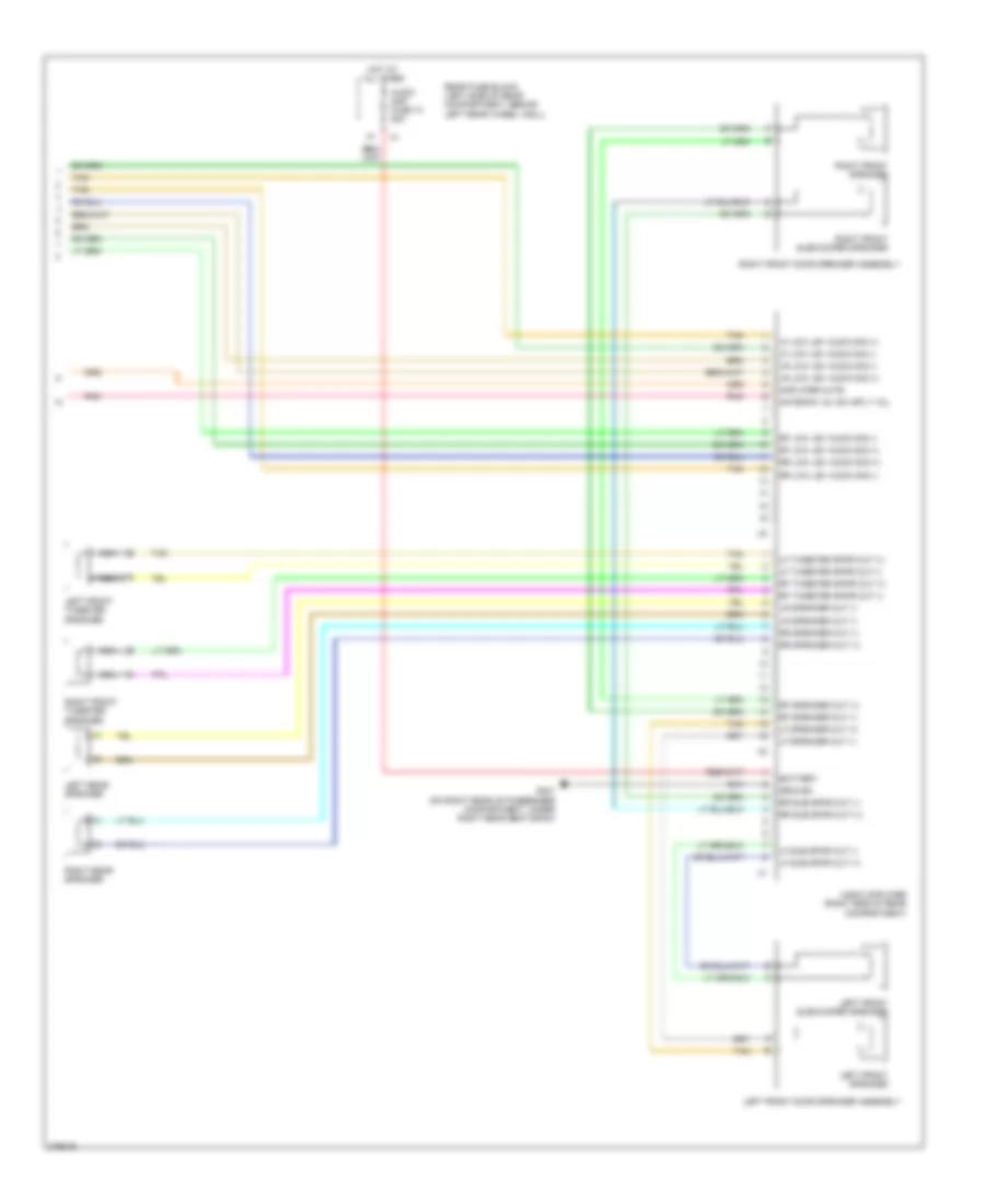 https://portal-diagnostov.com/license.html
Automotive Electricians Portal FZCO
Automotive Electricians Portal FZCO
https://portal-diagnostov.com/license.html
https://portal-diagnostov.com/license.html
Automotive Electricians Portal FZCO
Automotive Electricians Portal FZCOList of elements for 8-Speaker System Wiring Diagram, Convertible (2 of 2) for Pontiac G6 2008:
- Amplifier mute
- Antenna 12v sw sply vol
- Audio amp fuse 13 25a
- Audio amplifier (right side of rear compartment)
- Battery
- G301 (on right rear of passenger compartment, under right rear seat back)
- Ground
- Hot at all times
- Left front door speaker assembly
- Left front speaker
- Left front subwoofer speaker
- Left front tweeter speaker
- Left rear speaker
- Lf low lev audio sig (+)
- Lf low lev audio sig (-)
- Lf speaker out (+)
- Lf speaker out (-)
- Lf sub spkr out (+)
- Lf sub spkr out (-)
- Lf tweeter spkr out (+)
- Lf tweeter spkr out (-)
- Lr low lev audio sig (+)
- Lr low lev audio sig (-)
- Lr speaker out (-)
- Nca
- Pnk
- Rear fuse block (left side of rear compartment, behind left rear wheel well)
- Rf low lev audio sig (+)
- Rf low lev audio sig (-)
- Rf speaker out (+)
- Rf speaker out (-)
- Rf tweeter spkr out (+)
- Rf tweeter spkr out (-)
- Right front door speaker assembly
- Right front speaker
- Right front subwoofer speaker
- Right front tweeter speaker
- Right rear speaker
- Rr low lev audio sig (+)
- Rr low lev audio sig (-)
- Rr speaker out (+)
- Rr speaker out (-)
- Rr sub spkr out (+)
- Rr sub spkr out (-)
- Tan
8-Speaker System Wiring Diagram, Except Convertible (1 of 2) for Pontiac G6 2008
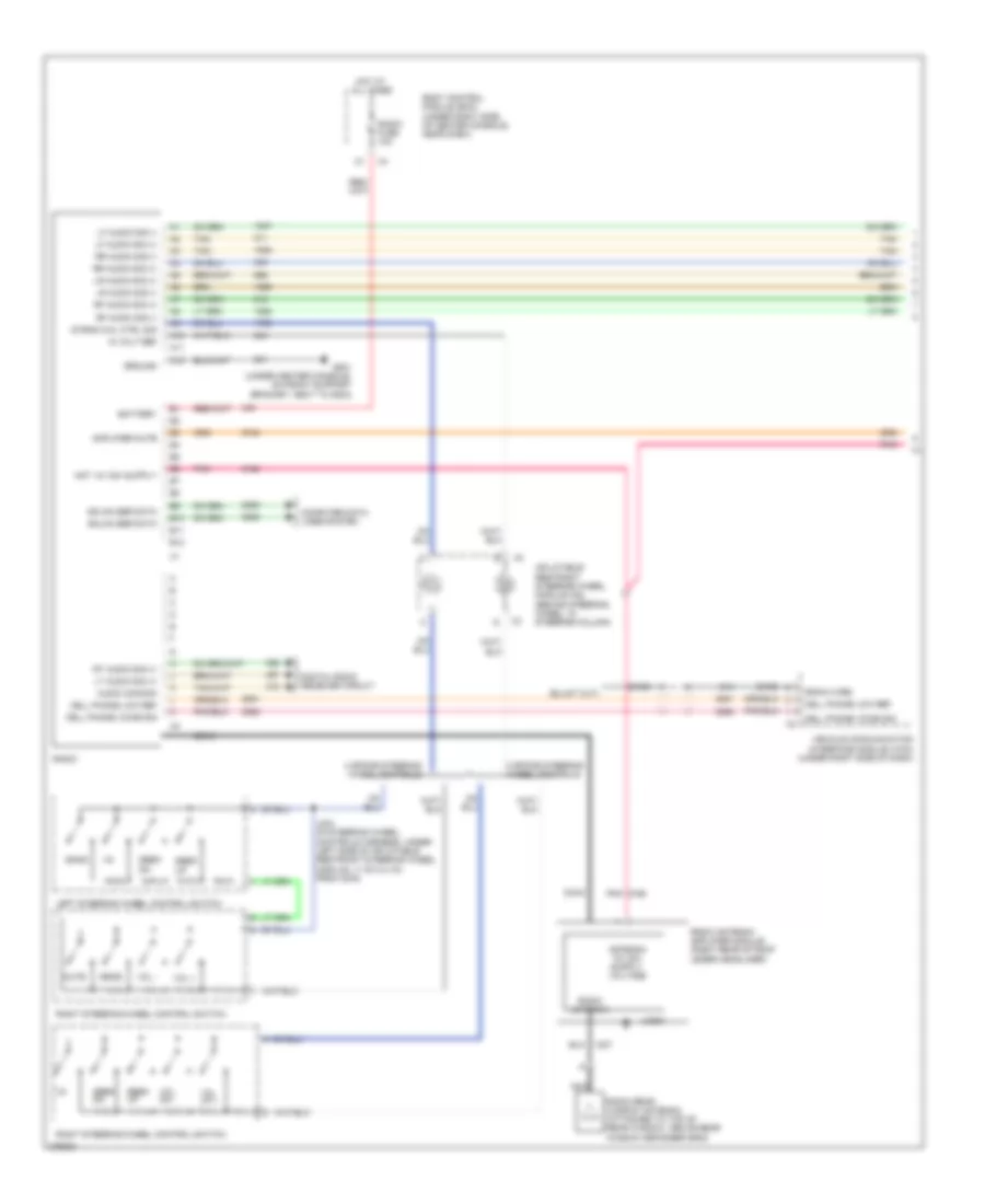 https://portal-diagnostov.com/license.html
Automotive Electricians Portal FZCO
Automotive Electricians Portal FZCO
https://portal-diagnostov.com/license.html
https://portal-diagnostov.com/license.html
Automotive Electricians Portal FZCO
Automotive Electricians Portal FZCOList of elements for 8-Speaker System Wiring Diagram, Except Convertible (1 of 2) for Pontiac G6 2008:
- 1-6
- 10 volt ref
- 3 spoke steering wheel controls
- 4 spoke steering wheel controls
- A10
- A11
- A12
- Amplifier mute
- Audio common
- B10
- B11
- B12
- Band
- Bare
- Battery
- Body control module (bcm) (under right side of center console, near dash)
- Cell phone low ref
- Cell phone voice sig
- Coax
- Computer data lines system
- Digital radio receiver circuit
- Drain wire
- G201 (under center console, on front support bracket, next to g203)
- Gmlan ser data
- Ground
- Hot at all times
- Inflatable restraint steering wheel module coil (behind steering wheel, in steering column)
- J203 (in steering wheel controls harness, under left side of inflatable restraint steering wheel module, 11 cm (4.4 in) from x276)
- Left steering wheel control switch
- Lf audio sig (+)
- Lf audio sig (-)
- Logic
- Lr audio sig (+)
- Lr audio sig (-)
- Lt audio sig (+)
- Mute
- Nca
- Pnk
- Radio
- Radio antenna
- Radio antenna amplifier module (right rear of roof under headliner)
- Radio fuse 10a
- Radio rear window antenna (attached to top of rear window, above rear window defogger grid)
- Rf audio sig (+)
- Rf audio sig (-)
- Right steering wheel control switch
- Rr audio sig (+)
- Rr audio sig (-)
- Rt audio sig (+)
- Seek
- Seek dn
- Seek up
- Srce
- Strng whl ctrl sig
- Tan
- Vehicle communication interface module (vcim) (under right side of dash)
- Vol +
- Vol -
- Vol dn -
- Vol up +
8-Speaker System Wiring Diagram, Except Convertible (2 of 2) for Pontiac G6 2008
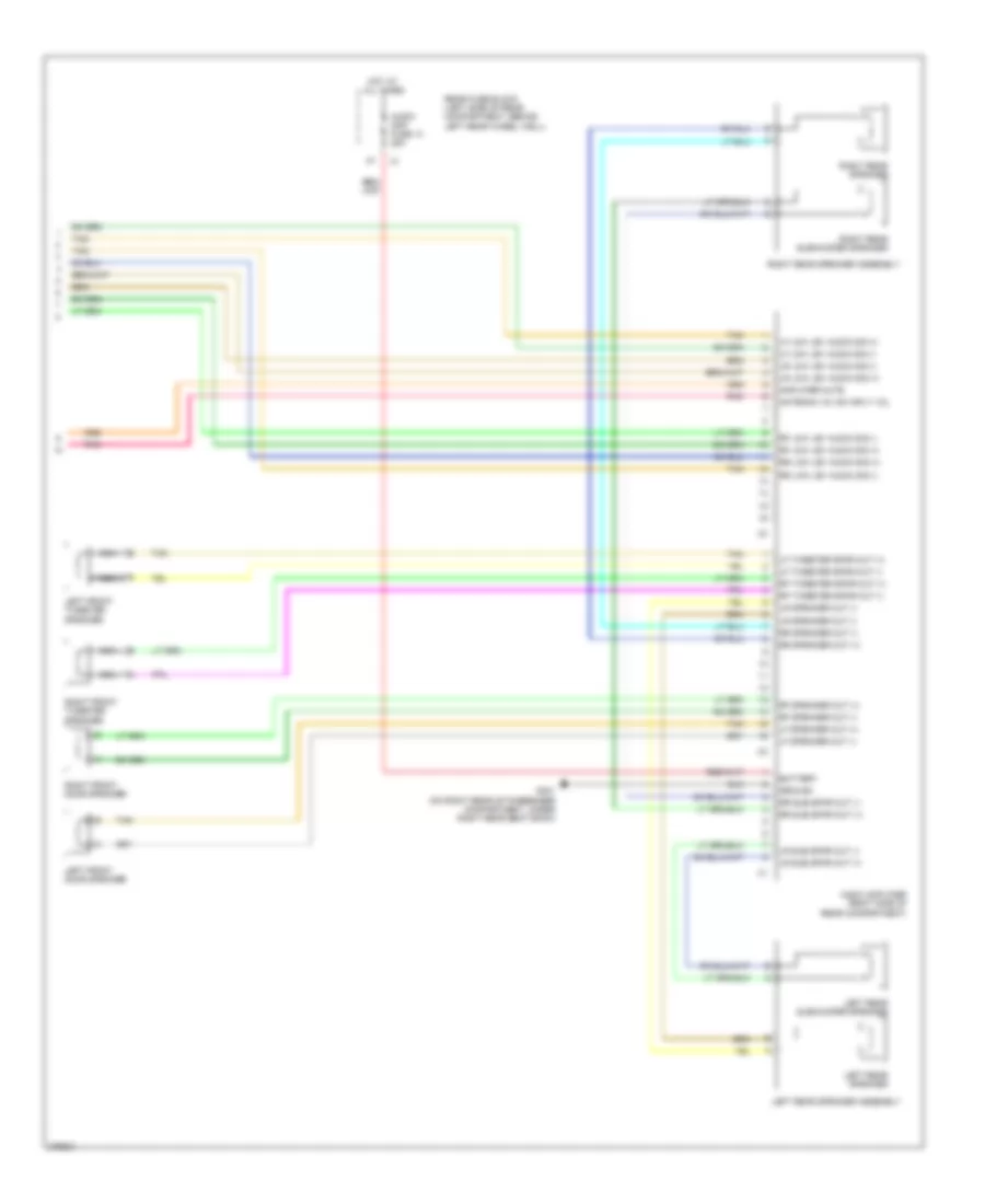 https://portal-diagnostov.com/license.html
Automotive Electricians Portal FZCO
Automotive Electricians Portal FZCO
https://portal-diagnostov.com/license.html
https://portal-diagnostov.com/license.html
Automotive Electricians Portal FZCO
Automotive Electricians Portal FZCOList of elements for 8-Speaker System Wiring Diagram, Except Convertible (2 of 2) for Pontiac G6 2008:
- Amplifier mute
- Antenna 12v sw sply vol
- Audio amp fuse 13 25a
- Audio amplifier (right side of rear compartment)
- Battery
- G301 (on right rear of passenger compartment, under right rear seat back)
- Ground
- Hot at all times
- Left front door speaker
- Left front tweeter speaker
- Left rear speaker
- Left rear speaker assembly
- Left rear subwoofer speaker
- Lf low lev audio sig (+)
- Lf low lev audio sig (-)
- Lf speaker out (+)
- Lf speaker out (-)
- Lf tweeter spkr out (+)
- Lf tweeter spkr out (-)
- Lr low lev audio sig (+)
- Lr low lev audio sig (-)
- Lr speaker out (-)
- Lr sub spkr out (+)
- Lr sub spkr out (-)
- Nca
- Pnk
- Rear fuse block (left side of rear compartment, behind left rear wheel well)
- Rf low lev audio sig (+)
- Rf low lev audio sig (-)
- Rf speaker out (+)
- Rf speaker out (-)
- Rf tweeter spkr out (+)
- Rf tweeter spkr out (-)
- Right front door speaker
- Right front tweeter speaker
- Right rear speaker
- Right rear speaker assembly
- Right rear subwoofer speaker
- Rr low lev audio sig (+)
- Rr low lev audio sig (-)
- Rr speaker out (+)
- Rr speaker out (-)
- Rr sub spkr out (+)
- Rr sub spkr out (-)
- Tan
Satellite Radio Wiring Diagram for Pontiac G6 2008
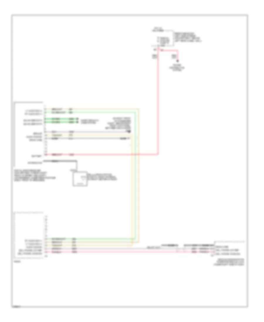 https://portal-diagnostov.com/license.html
Automotive Electricians Portal FZCO
Automotive Electricians Portal FZCO
https://portal-diagnostov.com/license.html
https://portal-diagnostov.com/license.html
Automotive Electricians Portal FZCO
Automotive Electricians Portal FZCOList of elements for Satellite Radio Wiring Diagram for Pontiac G6 2008:
- (on right front of passenger compt, behind right front kick panel, between g304 & door) g305
- Antenna sig
- Audio common
- Bare
- Battery
- Cell phone low ref
- Cell phone voice sig
- Cellular/navigation & digital radio antenna (in front center of roof)
- Coax
- Computer data lines system
- Digital radio receiver (convertible: in rear compt, front of spare tire compt) (coupe/sedan: under rear package shelf, front of speakers)
- Drain wire
- Gmlan ser data
- Ground
- Hot at all times
- Lt audio sig (+)
- Power distribution system
- Radio
- Rear fuse block (left side of rear compartment, behind left rear wheel well)
- Rke/xm/ dvd/ugd fuse 16 7.5a
- Rt audio sig (+)
- Vehicle communication interface module (vcim) (under right side of dash)
SHIFT INTERLOCK
Shift Interlock Wiring Diagram for Pontiac G6 2008
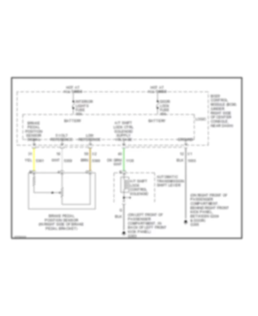 https://portal-diagnostov.com/license.html
Automotive Electricians Portal FZCO
Automotive Electricians Portal FZCO
https://portal-diagnostov.com/license.html
https://portal-diagnostov.com/license.html
Automotive Electricians Portal FZCO
Automotive Electricians Portal FZCOList of elements for Shift Interlock Wiring Diagram for Pontiac G6 2008:
- (on left front of passenger compartment, in back of left front kick panel) g303
- (on right front of passenger compartment, behind right front kick panel, between g304 & door) g305
- 5 volt reference
- A/t shift lock control solenoid
- Automatic transmission shift lever
- Battery
- Body control module (bcm) (under right side of center console, near dash)
- Brake pedal position sensor (in right side of brake pedal bracket)
- Brake pedal position sensor signal
- Door lock fuse 15a
- Ground
- Hot at all times
- Interior lights fuse 10a
- Logic
- Low reference
STARTING/CHARGING
Charging Wiring Diagram for Pontiac G6 2008
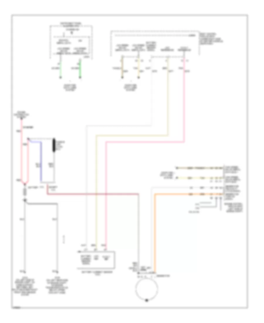 https://portal-diagnostov.com/license.html
Automotive Electricians Portal FZCO
Automotive Electricians Portal FZCO
https://portal-diagnostov.com/license.html
https://portal-diagnostov.com/license.html
Automotive Electricians Portal FZCO
Automotive Electricians Portal FZCOList of elements for Charging Wiring Diagram for Pontiac G6 2008:
- (not used)
- (on left rear side of engine compt, on engine transmission stud, below upper coolant hose)
- 2.4l
- 3.5l & 3.9l
- 3.6l
- 5-volt ref
- 5-volt reference
- Battery
- Battery current sensor (3.6l)
- Battery current sensor signal
- Body control module (bcm) (under right side of center console, near dash)
- Charge ind
- Computer data lines system
- Ecm/pcm serial data
- Engine control module (ecm) (left side of engine compt)
- Except 2.4l
- G104 (on left side of engine compt, on core support, between left inflatable restraint front end sensor & g109)
- G105
- Generator
- Generator field duty cycle signal
- Generator turn on signal
- High speed gmlan serial data bus +
- High speed gmlan serial data bus -
- Ign
- Instrument panel cluster (ipc)
- Logic
- Low ref
- Low reference
- Low speed gmlan serial data
- Pnk
- Power distribution system
- Red
- Starter
- Tan
Starting Wiring Diagram for Pontiac G6 2008
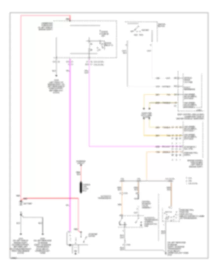 https://portal-diagnostov.com/license.html
Automotive Electricians Portal FZCO
Automotive Electricians Portal FZCO
https://portal-diagnostov.com/license.html
https://portal-diagnostov.com/license.html
Automotive Electricians Portal FZCO
Automotive Electricians Portal FZCOList of elements for Starting Wiring Diagram for Pontiac G6 2008:
- (2.4l & 3.6l)
- (3.5l & 3.9l)
- (on left rear side of engine compt, on engine transmission stud, below upper coolant hose) g105
- 2.4l
- 2.4l & 3.5l (a/t)
- 3.5l & 3.9l
- 3.6l
- 3.6l (a/t)
- 3.9l (a/t)
- 5-volt reference
- A x1
- Automatic transmission
- Automatic transmission internal mode switch (ims)
- Battery
- Body control module (bcm) (under right side of center console, near dash)
- C1 x2
- C10 x2
- Charging circuit
- Computer data lines system
- Control solenoid valve assembly
- D12 x1
- Engine control module (ecm) (left side of engine compt)
- G104 (on left side of engine compt, on core support, between left inflatable restraint front end sensor & g109)
- G105 (on left rear side of engine compt, on engine transmission stud, below upper coolant hose)
- G109 (left front of engine compt, on left rear side of core support, between g101 & g104)
- High speed gmlan serial data bus +
- High speed gmlan serial data bus -
- Ignition switch
- K x100
- Logic
- Nca
- Off
- Off/run/ crank voltage
- Park/neutral position (pnp) switch (below master cylinder, on transmission)
- Park/neutral signal
- Red
- Run acc
- Start
- Starter motor
- Starter rly coil ctrl
- Strtr fuse 26 30a
- Strtr relay 31
- Tan
- Underhood fuse block (in left side of engine compt)
- W x100
- X1 e12
SUPPLEMENTAL RESTRAINTS
Supplemental Restraints Wiring Diagram (1 of 3) for Pontiac G6 2008
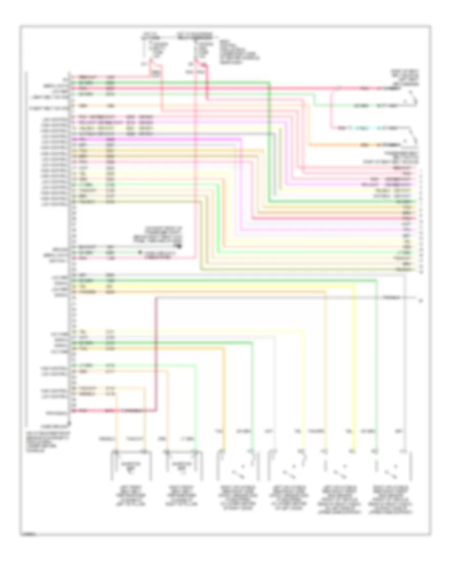 https://portal-diagnostov.com/license.html
Automotive Electricians Portal FZCO
Automotive Electricians Portal FZCO
https://portal-diagnostov.com/license.html
https://portal-diagnostov.com/license.html
Automotive Electricians Portal FZCO
Automotive Electricians Portal FZCOList of elements for Supplemental Restraints Wiring Diagram (1 of 3) for Pontiac G6 2008:
- (on right front of passenger compt, behind right front kick panel, forward of g305) g304
- (or 900)
- (or 901)
- (part of seat belt buckle) left seat belt switch
- Air bag (batt) fuse 10a
- Air bag (ign) fuse 10a
- Body control module (bcm) (under right side of center console, near dash)
- Case ground
- Computer data lines system
- D11
- Ground
- High control
- Hot at all times
- Hot w/ run/crank relay energized
- Ignition 1
- Inflatable restraint sensing & diagnostic module (sdm) (under center console)
- L seat belt sw sig
- Left front seat belt pretensioner (in base of left "b" pillar)
- Left inflatable restraint front end sensor (front of vehicle, rear of front fascia, on left side of upper core support)
- Left inflatable restraint side impact sensor (sis) (if equipped) (in lower center of left door)
- Low control
- Low ref
- Nca
- Passenger seat belt switch (part of seat belt buckle)
- Pnk
- Pps signal
- R seat belt sw sig
- Right front seat belt pretensioner (in base of right "b" pillar)
- Right inflatable restraint front end sensor (front of vehicle, rear of front fascia, on right side of upper core support)
- Right inflatable restraint side impact sensor (sis) (if equipped) (in lower center of right door)
- Serial data
- Shorting bar
- Signal
- Tan
- Voltage
Supplemental Restraints Wiring Diagram (2 of 3) for Pontiac G6 2008
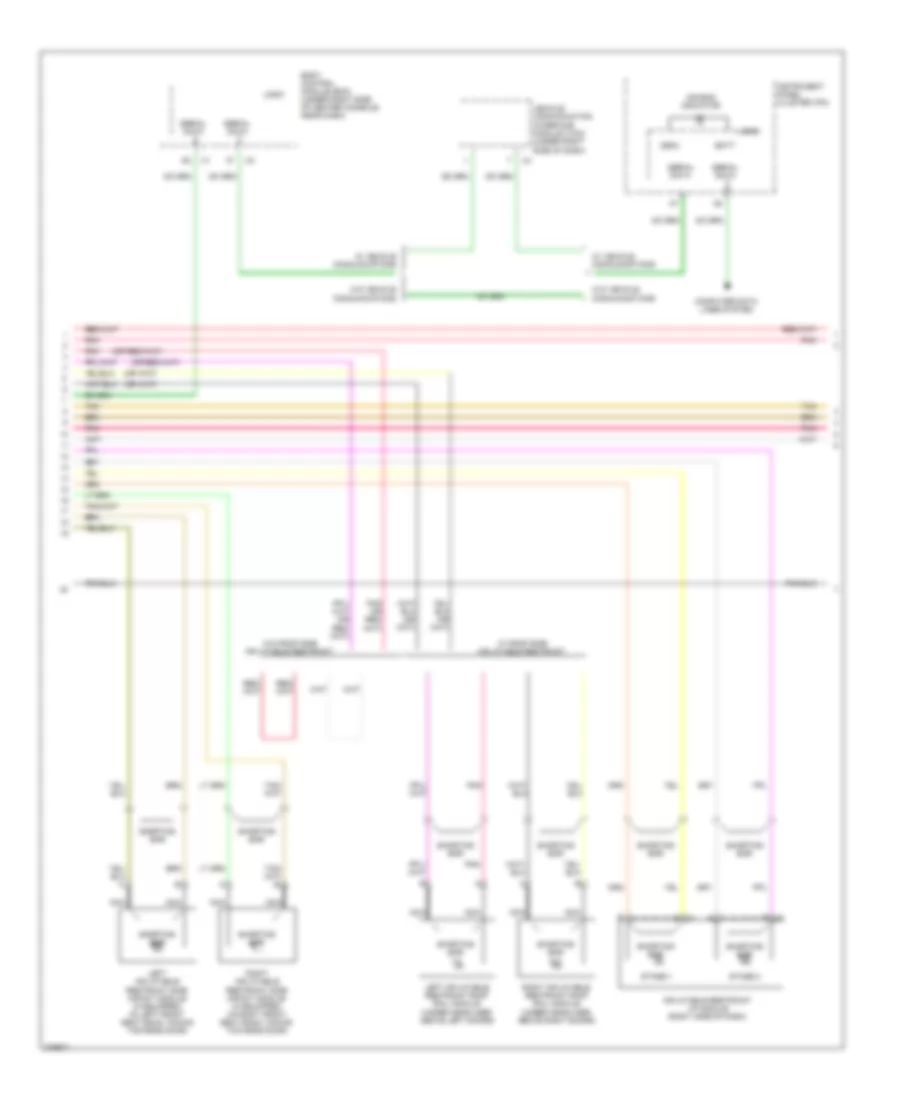 https://portal-diagnostov.com/license.html
Automotive Electricians Portal FZCO
Automotive Electricians Portal FZCO
https://portal-diagnostov.com/license.html
https://portal-diagnostov.com/license.html
Automotive Electricians Portal FZCO
Automotive Electricians Portal FZCOList of elements for Supplemental Restraints Wiring Diagram (2 of 3) for Pontiac G6 2008:
- (sdm)
- A x1
- Air bag indicator
- B x2
- Batt
- Body control module (bcm) (under right side of center console, near dash)
- Computer data lines system
- Inflatable restraint i/p module (right side of dash)
- Instrument panel cluster (ipc)
- Left inflatable restraint roof rail module (under headliner, above left doors)
- Left inflatable restraint side impact module (if equipped) (in left front seat back, facing towards door)
- Logic
- Nca
- Pnk
- Right inflatable restraint roof rail module (under headliner, above right doors)
- Right inflatable restraint side impact module (if equipped) (in right front seat back, facing towards door)
- Serial data
- Shorting bar
- Stage 1
- Stage 2
- Tan
- Vehicle communication interface module (vcim) (under right side of dash)
- W/ roof side inflatable restraint
- W/ vehicle communications
- W/o roof side inflatable restraint
- W/o vehicle communications
Supplemental Restraints Wiring Diagram (3 of 3) for Pontiac G6 2008
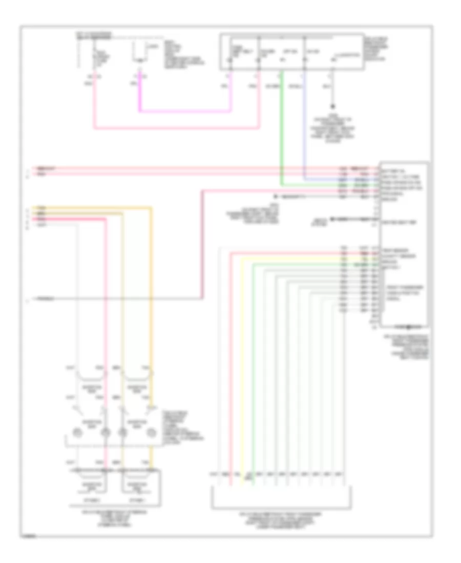 https://portal-diagnostov.com/license.html
Automotive Electricians Portal FZCO
Automotive Electricians Portal FZCO
https://portal-diagnostov.com/license.html
https://portal-diagnostov.com/license.html
Automotive Electricians Portal FZCO
Automotive Electricians Portal FZCOList of elements for Supplemental Restraints Wiring Diagram (3 of 3) for Pontiac G6 2008:
- B10
- Battery b+
- Body control module (bcm) (under right side of center console, near dash)
- Case ground
- Front passenger
- G304 (on right front of passenger compt, behind right front kick panel, forward of g305)
- G305 (on right front of passenger compartment, behind right front kick panel, between g304 & door)
- Ground
- Heated seat ref
- Hot w/ run/crank relay energized
- Humidity sensor
- Ignition 1
- Ignition 1 voltage
- Illumination
- Ind
- Inflatable restraint front passenger presence system (pps) module (inside passenger seat cushion)
- Inflatable restraint front passenger presence system (pps) sensor (right front of passenger compt, under passenger seat)
- Inflatable restraint passenger air bag on/off indicator
- Inflatable restraint steering wheel module (in center of steering wheel)
- Inflatable restraint steering wheel module coil (behind steering wheel, in steering column)
- Logic
- Mass & position
- Off ind
- On ind
- Pass air bag off ind
- Pass air bag on ind
- Pass seat belt ind
- Pnk
- Power ind
- Pps signal
- Red
- Run/ crank fuse 2a
- Seats system
- Shorting bar
- Signal
- Stage 1
- Stage 2
- Tan
- Temp sensor
- X3 a8
TRANSMISSION
2.4L VIN B
2.4L VIN B, Transmission Wiring Diagram (1 of 2) for Pontiac G6 2008
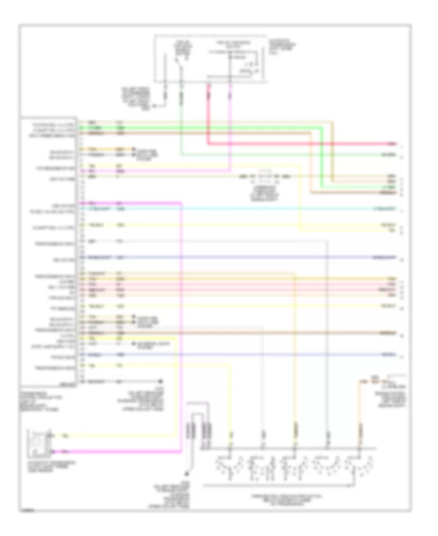 https://portal-diagnostov.com/license.html
Automotive Electricians Portal FZCO
Automotive Electricians Portal FZCO
https://portal-diagnostov.com/license.html
https://portal-diagnostov.com/license.html
Automotive Electricians Portal FZCO
Automotive Electricians Portal FZCOList of elements for 2.4L VIN B, Transmission Wiring Diagram (1 of 2) for Pontiac G6 2008:
- (on left front of passenger compt, in back of left front kick panel) g303
- (tfp) sw sig c
- 1-2 shift sol vlv ctrl
- 2-3 shift sol vlv ctrl
- Acc voltage
- Automatic transmission output shaft speed (oss) sensor
- Automatic transmission shift lever (3.5l)
- C pnk
- Computer data lines system
- Cyl ctrl sig x3
- Down
- Engine control module (ecm) (left side of engine compt)
- Exterior lights system
- G105 (on left rear side of engine compt, on engine transmission stud, below upper coolant hose)
- Gmlan data +
- Gmlan data -
- Ground
- Hi ctrl
- Ign 1 voltage
- Input speed sens hi sig
- Iss low sig
- Low ref
- Park/neutral position (pnp) switch (below master cylinder, on transmission)
- Pc sol valve low ctrl
- Pnk
- Tan
- Tap up/ tap down enable switch
- Tap up/ tap down switch
- Tcc pwm sol vlv ctrl
- Tcc release sw sig
- Tfp sw sig b
- Tft sens sig
- Transmission control module (tcm) (left of engine compt, near strut tower)
- Trns range sw sig a
- Trns range sw sig b
- Trns range sw sig c
- Trns range sw sig p
- Underhood fuse block (in left side of engine compt)
- Vss hi sig
- Vss low sig
2.4L VIN B, Transmission Wiring Diagram (2 of 2) for Pontiac G6 2008
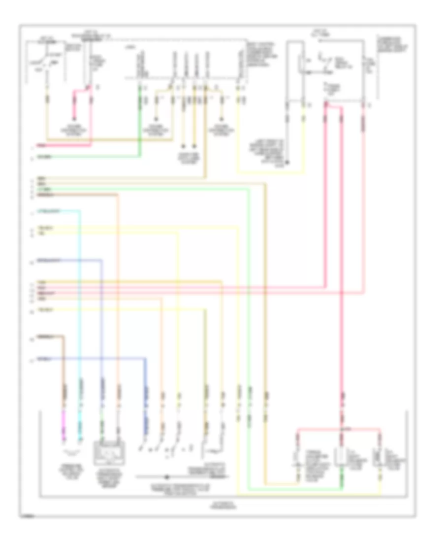 https://portal-diagnostov.com/license.html
Automotive Electricians Portal FZCO
Automotive Electricians Portal FZCO
https://portal-diagnostov.com/license.html
https://portal-diagnostov.com/license.html
Automotive Electricians Portal FZCO
Automotive Electricians Portal FZCOList of elements for 2.4L VIN B, Transmission Wiring Diagram (2 of 2) for Pontiac G6 2008:
- (left front of engine compt, on left rear side of core support, between g101 & g104) g109
- 1-2 shift solenoid (1-2 ss) valve
- 2-3 shift solenoid (2-3 ss) valve
- Acc
- Acc voltage
- Automatic transmission
- Automatic transmission fluid pressure (tfp) manual valve position switch
- Automatic transmission fluid temperature (tft) sensor
- Automatic transmission input shaft speed (iss) sensor
- Body control module (bcm) (under right side of center console, near dash)
- C10
- Computer data lines system
- Down enable tap up/ tap
- Gmlan data +
- Gmlan data -
- Hot at all times
- Hot w/ run/crank relay 32 energized
- Ignition switch
- J103
- Lock
- Logic
- Pnk
- Power distribution system
- Pressure control (pc) solenoid valve
- Red
- Red a
- Rly coil ctrl
- Run
- Run/ crank fuse 2a
- Run/ crank relay 32
- Sig
- Start
- Tan
- Tcc
- Tcm fuse 10a
- Torque converter clutch pulse width modulation (tcc pwm) solenoid valve
- Trans fuse 4 10a
- Underhood fuse block (in left side of engine compt)
3.5L VIN N
3.5L VIN N, Transmission Wiring Diagram (1 of 2) for Pontiac G6 2008
 https://portal-diagnostov.com/license.html
Automotive Electricians Portal FZCO
Automotive Electricians Portal FZCO
https://portal-diagnostov.com/license.html
https://portal-diagnostov.com/license.html
Automotive Electricians Portal FZCO
Automotive Electricians Portal FZCOList of elements for 3.5L VIN N, Transmission Wiring Diagram (1 of 2) for Pontiac G6 2008:
- (on left front of passenger compt, in back of left front kick panel) g303
- (tfp) sw sig c
- 1-2 shift sol vlv ctrl
- 2-3 shift sol vlv ctrl
- Acc voltage
- Automatic transmission output shaft speed (oss) sensor
- Automatic transmission shift lever (3.5l)
- C pnk
- Computer data lines system
- Cyl ctrl sig x3
- Down
- Engine control module (ecm) (left side of engine compt)
- Exterior lights system
- G105 (on left rear side of engine compt, on engine transmission stud, below upper coolant hose)
- Gmlan data +
- Gmlan data -
- Ground
- Hi ctrl
- Ign 1 voltage
- Input speed sens hi sig
- Iss low sig
- Low ref
- Park/neutral position (pnp) switch (below master cylinder, on transmission)
- Pc sol valve low ctrl
- Pnk
- Tan
- Tap up/ tap down enable switch
- Tap up/ tap down switch
- Tcc pwm sol vlv ctrl
- Tcc release sw sig
- Tfp sw sig b
- Tft sens sig
- Transmission control module (tcm) (left of engine compt, near strut tower)
- Trns range sw sig a
- Trns range sw sig b
- Trns range sw sig c
- Trns range sw sig p
- Underhood fuse block (in left side of engine compt)
- Vss hi sig
- Vss low sig
3.5L VIN N, Transmission Wiring Diagram (2 of 2) for Pontiac G6 2008
 https://portal-diagnostov.com/license.html
Automotive Electricians Portal FZCO
Automotive Electricians Portal FZCO
https://portal-diagnostov.com/license.html
https://portal-diagnostov.com/license.html
Automotive Electricians Portal FZCO
Automotive Electricians Portal FZCOList of elements for 3.5L VIN N, Transmission Wiring Diagram (2 of 2) for Pontiac G6 2008:
- (left front of engine compt, on left rear side of core support, between g101 & g104) g109
- 1-2 shift solenoid (1-2 ss) valve
- 2-3 shift solenoid (2-3 ss) valve
- Acc
- Acc voltage
- Automatic transmission
- Automatic transmission fluid pressure (tfp) manual valve position switch
- Automatic transmission fluid temperature (tft) sensor
- Automatic transmission input shaft speed (iss) sensor
- Body control module (bcm) (under right side of center console, near dash)
- C10
- Computer data lines system
- Down enable tap up/ tap
- Gmlan data +
- Gmlan data -
- Hot at all times
- Hot w/ run/crank relay 32 energized
- Ignition switch
- J103
- Lock
- Logic
- Pnk
- Power distribution system
- Pressure control (pc) solenoid valve
- Red
- Red a
- Rly coil ctrl
- Run
- Run/ crank fuse 2a
- Run/ crank relay 32
- Sig
- Start
- Tan
- Tcc
- Tcm fuse 10a
- Torque converter clutch pulse width modulation (tcc pwm) solenoid valve
- Trans fuse 4 10a
- Underhood fuse block (in left side of engine compt)
3.6L VIN 7
3.6L VIN 7, Transmission Wiring Diagram (1 of 2) for Pontiac G6 2008
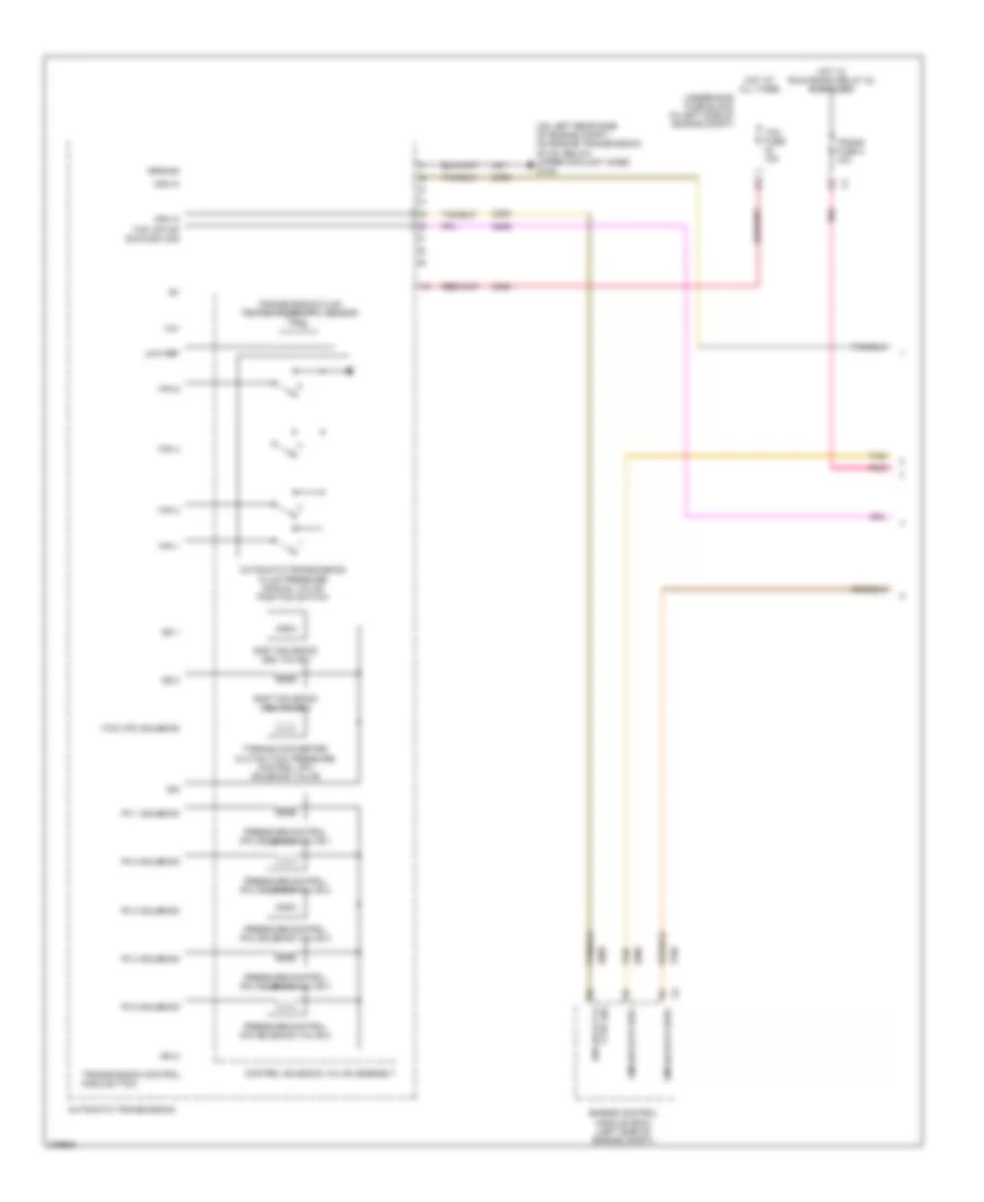 https://portal-diagnostov.com/license.html
Automotive Electricians Portal FZCO
Automotive Electricians Portal FZCO
https://portal-diagnostov.com/license.html
https://portal-diagnostov.com/license.html
Automotive Electricians Portal FZCO
Automotive Electricians Portal FZCOList of elements for 3.6L VIN 7, Transmission Wiring Diagram (1 of 2) for Pontiac G6 2008:
- (on left rear side of engine compt, on engine transmission stud, below upper coolant hose) g105
- (tcc) (pc) solenoid
- Automatic transmission
- Automatic transmission fluid pressure manual valve position switch
- Can hi
- Control solenoid valve assembly
- Engine control module (ecm) (left side of engine compt)
- Gmlan data bus+
- Gmlan data bus-
- Ground
- Hot at all times
- Hot w/ run/crank relay 32 energized
- Ign
- Ign 2
- Ign lock cyl ctrl sig
- Low ref
- Pc 1 solenoid
- Pc 2 solenoid
- Pc 3 solenoid
- Pc 4 solenoid
- Pc 5 solenoid
- Pnk
- Pressure control (pc) solenoid valve 1
- Pressure control (pc) solenoid valve 2
- Pressure control (pc) solenoid valve 3
- Pressure control (pc) solenoid valve 4
- Pressure control (pc) solenoid valve 5
- Shift solenoid (ss) valve 1
- Shift solenoid (ss) valve 2
- Ss 1
- Ss 2
- Tan
- Tap up/tap down sw sig
- Tcm fuse 10a
- Tfp 1
- Tfp 3
- Tfp 4
- Tfp 5
- Tft
- Torque converter clutch (tcc) pressure control (pc) solenoid valve
- Trans fuse 4 10a
- Transmission control module (tcm)
- Transmission fluid temperature (tft) sensor
- Underhood fuse block (in left side of engine compt)
3.6L VIN 7, Transmission Wiring Diagram (2 of 2) for Pontiac G6 2008
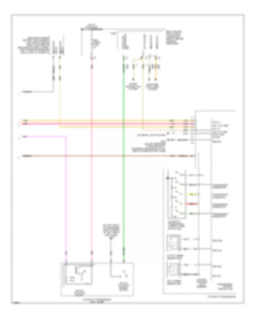 https://portal-diagnostov.com/license.html
Automotive Electricians Portal FZCO
Automotive Electricians Portal FZCO
https://portal-diagnostov.com/license.html
https://portal-diagnostov.com/license.html
Automotive Electricians Portal FZCO
Automotive Electricians Portal FZCOList of elements for 3.6L VIN 7, Transmission Wiring Diagram (2 of 2) for Pontiac G6 2008:
- (on left front of passenger compt, in back of left front kick panel) g303
- Acc voltage
- Automatic transmission
- Automatic transmission internal mode switch (ims)
- Automatic transmission shift lever
- Body control module (bcm) (under right side of center console, near dash)
- Can lo
- Computer data lines system
- Control solenoid valve assembly
- Down
- Down enable tap up/ tap
- Electronic brake control module (ebcm) (left side of engine compt, mounted to back side of strut tower, part of brake pressure modulator valve (bpmv))
- Exterior lights system
- G105 (on left rear side of engine compt, on engine transmission stud, below upper coolant hose)
- Gmlan data +
- Gmlan data -
- Gmlan data bus (+)
- Gmlan data bus (-)
- Ground
- Hot w/ run/crank relay 32 energized
- Ign 1 voltage
- Input speed sensor (iss)
- Iss high
- Iss low
- Logic
- Oss high
- Oss low
- Output speed sensor (oss)
- Pnk
- Power distribution system
- Red d
- Run/ crank fuse 2a
- Sig
- Stop lamp sw sig
- Tan
- Tap up/ tap down enable switch
- Tap up/ tap down switch
- Transmission control module (tcm)
- Transmission range sig b
- Transmission range sig c
- Transmission range sig d
- Transmission range sig e
3.9L VIN 1
3.9L VIN 1, Transmission Wiring Diagram (1 of 2) for Pontiac G6 2008
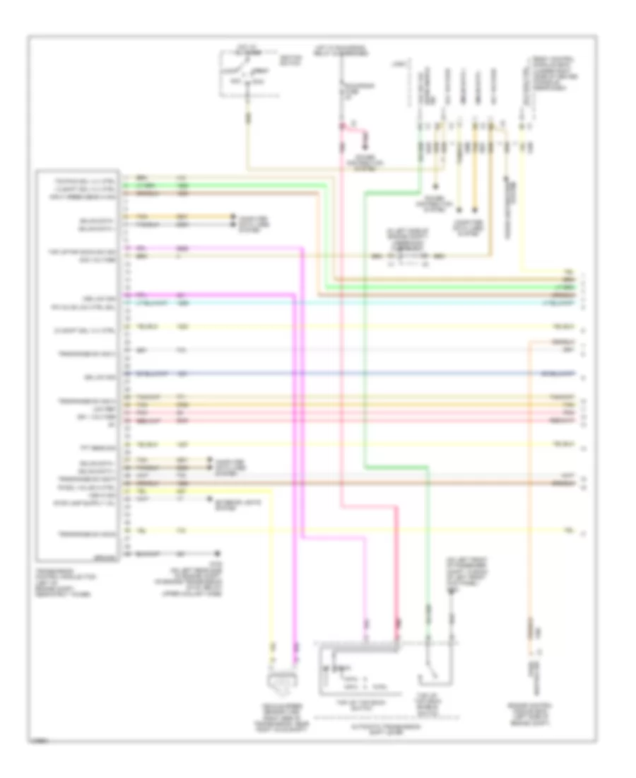 https://portal-diagnostov.com/license.html
Automotive Electricians Portal FZCO
Automotive Electricians Portal FZCO
https://portal-diagnostov.com/license.html
https://portal-diagnostov.com/license.html
Automotive Electricians Portal FZCO
Automotive Electricians Portal FZCOList of elements for 3.9L VIN 1, Transmission Wiring Diagram (1 of 2) for Pontiac G6 2008:
- (in left side of engine compt) underhood fuse block
- (on left front of passenger compt, in back of left front kick panel) g303
- 1-2 shift sol vlv ctrl
- 2-3 shift sol vlv ctrl
- Acc
- Acc voltage
- Automatic transmission shift lever
- Body control module (bcm) (under right side of center console, near dash)
- Computer data lines system
- Down
- Down enable tap up/ tap
- Engine control module (ecm) (left side of engine compt)
- Exterior lights system
- G105 (on left rear side of engine compt, on engine transmission stud, below upper coolant hose)
- Gmlan data +
- Gmlan data -
- Ground
- Hot at all times
- Hot w/ run/crank relay 32 energized
- Ign 1 voltage
- Ignition switch
- Input speed sens hi sig
- Iss low sig
- Lock
- Logic
- Low ref
- Pc sol valve hi ctrl
- Pc valve low ctrl sol
- Pnk
- Power distribution system
- Rly coil ctrl
- Run
- Run/crank fuse 2a
- Sig
- Start
- Tan
- Tap up/ tap down enable switch
- Tap up/ tap down switch
- Tap up/tap down sw sig
- Tcc pwm sol vlv ctrl
- Tft sens sig
- Transmission control module (tcm) (left of engine compt, near strut tower)
- Trns range sw sig a
- Trns range sw sig b
- Trns range sw sig c
- Trns range sw sig p
- Vehicle speed sensor (vss) (right side of transmission, near right axle shaft)
- Vss hi sig
- Vss low sig
- X1 neutral sw park/
3.9L VIN 1, Transmission Wiring Diagram (2 of 2) for Pontiac G6 2008
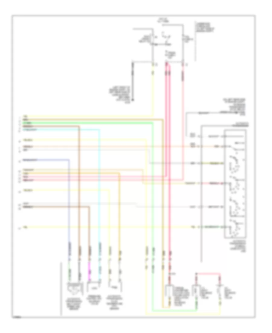 https://portal-diagnostov.com/license.html
Automotive Electricians Portal FZCO
Automotive Electricians Portal FZCO
https://portal-diagnostov.com/license.html
https://portal-diagnostov.com/license.html
Automotive Electricians Portal FZCO
Automotive Electricians Portal FZCOList of elements for 3.9L VIN 1, Transmission Wiring Diagram (2 of 2) for Pontiac G6 2008:
- (left front of engine compt, on left rear side of core support, between g101 & g104) g109
- (on left rear side of engine compt, on engine transmission stud, below upper coolant hose) g105
- 1-2 shift solenoid (ss) valve
- 2-3 shift solenoid (ss) valve
- Automatic transmission
- Automatic transmission fluid temperature (tft) sensor
- Automatic transmission input shaft speed (iss) sensor
- Automatic transmission internal mode switch (ims)
- C10
- Hot at all times
- J103
- Pnk
- Pressure control (pc) solenoid valve
- Red
- Red a
- Run/ crank relay 32
- Tan
- Tcm fuse 42 10a
- Torque converter clutch (tcc) pulse width modulation (pwm) solenoid valve
- Trans fuse 4 10a
- Underhood fuse block (in left side of engine compt)
TRUNK, TAILGATE, FUEL DOOR
Trunk Release Wiring Diagram for Pontiac G6 2008
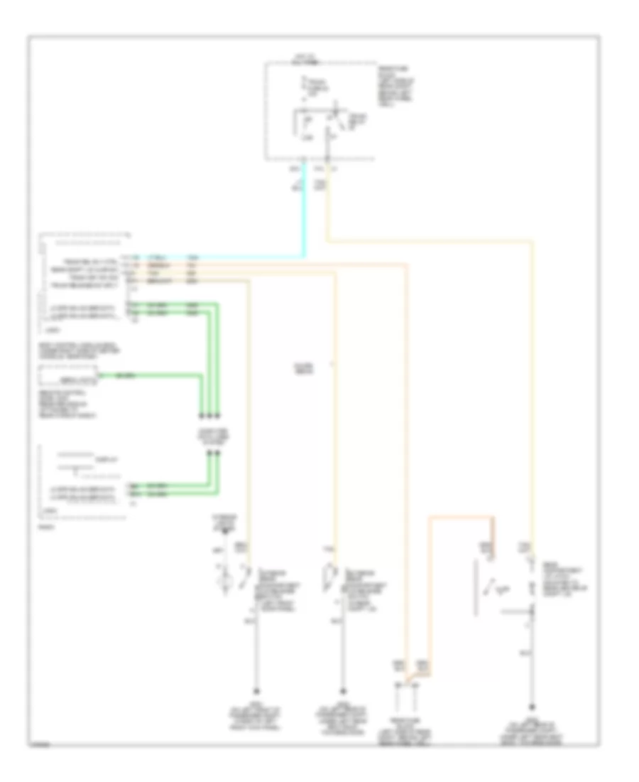 https://portal-diagnostov.com/license.html
Automotive Electricians Portal FZCO
Automotive Electricians Portal FZCO
https://portal-diagnostov.com/license.html
https://portal-diagnostov.com/license.html
Automotive Electricians Portal FZCO
Automotive Electricians Portal FZCOList of elements for Trunk Release Wiring Diagram for Pontiac G6 2008:
- Ajar
- B10
- Body control module (bcm) (under right side of center console, near dash)
- Computer data lines system
- Coupe/ sedan
- Display
- E10
- Exterior rear compartment lid release switch (in rear compt lid)
- F10
- G302 (on left rear of passenger compt,
- G302 (on left rear of passenger compt, under left rear seat back, towards door)
- G303 (on left front of passenger compt, in back of left front kick panel)
- Hot at all times
- Interior lights system
- Interior rear compartment lid release switch (left front door panel)
- Lo spd gmlan ser data
- Logic
- Radio
- Rear compartment lid latch (mounted to rear center of compt lid)
- Rear compt lid ajar sw
- Rear fuse block (left side of rear compt, behind left rear wheel well)
- Remote control door lock receiver (rcdlr) (attached to rear window shelf)
- Serial data
- Tan
- Trunk fuse 22 10a
- Trunk key sw sig
- Trunk rel rly ctrl
- Trunk relay
- Trunk release sw sply
- Under left rear seat back, towards door)
WARNING SYSTEMS
Warning Systems Wiring Diagram for Pontiac G6 2008
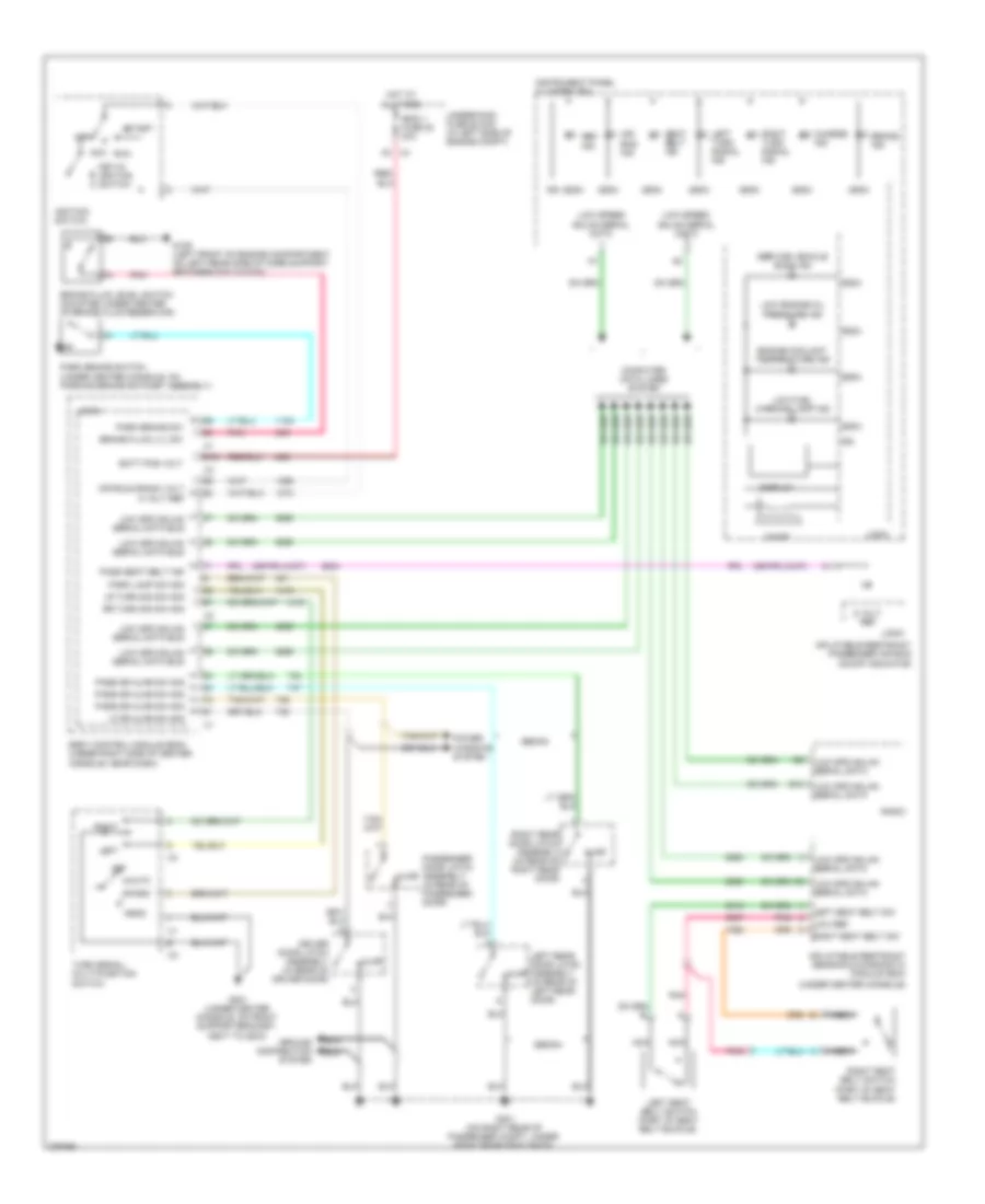 https://portal-diagnostov.com/license.html
Automotive Electricians Portal FZCO
Automotive Electricians Portal FZCO
https://portal-diagnostov.com/license.html
https://portal-diagnostov.com/license.html
Automotive Electricians Portal FZCO
Automotive Electricians Portal FZCOList of elements for Warning Systems Wiring Diagram for Pontiac G6 2008:
- (sdm)
- (under center console)
- 5 volt ref
- A3 x4
- Abs ind
- Acc
- Air bag ind
- Ajar
- Auto
- B10
- Batt pos volt
- Body control module (bcm) (under right side of center console, near dash)
- Brake fluid level switch (mounted under center of brake fluid reservoir)
- Brake fluid lvl sw
- Brake ind
- Charge ind
- Chime
- Computer data lines system
- D12
- Display
- Driver door latch assembly (in rear of driver door)
- Engine coolant temperature ind
- G109 (left front of engine compartment, on left rear side of core support, between g101 & g104)
- G201 (under center console, on front support bracket, next to g203)
- G301 (on right rear of passenger compt, under right rear seat back)
- Ground distribution system
- Head
- Hot at all times
- Ibcm 1 fuse 20 30a
- Ign
- Ignition switch
- Inflatable restraint passenger air bag on/off indicator
- Inflatable restraint sensing & diagnostic module (sdm)
- Instrument panel cluster (ipc)
- Key-in ignition switch
- Left
- Left rear door latch assembly (in rear of left rear door)
- Left seat belt sw
- Left seat belt switch (part of seat belt buckle)
- Left turn signal ind
- Lf dr ajar sw sig
- Logic
- Low engine oil pressure ind
- Low fuel warning lamp ind
- Low ref
- Low spd gmlan serial data
- Low spd gmlan serial data bus
- Low speed gmlan serial data
- Lr turn sig sw sig
- Nca
- Off
- Off/run/crank volt
- Park
- Park brake sw
- Park brake switch (under center console, on parking brake ratchet assembly)
- Park lamp sw sig
- Pass dr ajar sw sig
- Pass seat belt ind
- Passenger door latch assembly (in rear of passenger door)
- Pnk
- Power windows system
- Radio
- Right
- Right rear door latch assembly (in rear of right rear door)
- Right seat belt sw
- Right seat belt switch (part of seat belt buckle)
- Right turn signal ind
- Rr turn sig sw sig
- Run
- Seat belt ind
- Sedan
- Service vehicle soon ind
- Start
- Turn signal/ multi-function switch
- Underhood fuse block (in left side of engine compt)
WIPER/WASHER
Wiper/Washer Wiring Diagram for Pontiac G6 2008
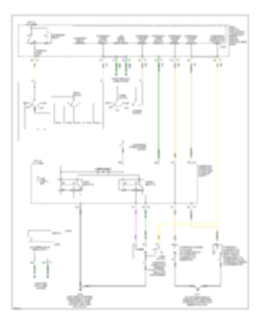 https://portal-diagnostov.com/license.html
Automotive Electricians Portal FZCO
Automotive Electricians Portal FZCO
https://portal-diagnostov.com/license.html
https://portal-diagnostov.com/license.html
Automotive Electricians Portal FZCO
Automotive Electricians Portal FZCOList of elements for Wiper/Washer Wiring Diagram for Pontiac G6 2008:
- (on left rear side of core support, between windshield washer fluid reservoir & g109)
- 87a
- Accessory relay
- Accessory relay control
- B10
- Body control module (bcm) (under right side of center console, near dash)
- C10
- C12
- Computer data lines system
- Delay switch
- Display
- G101
- G109 (left front of engine compartment, on left rear side of core support, between g101 & g104)
- High
- Hot at all times
- Int
- Logic
- Low
- Low speed gmlan serial data
- Mist
- Off
- Park switch
- Radio
- Underhood fuse block (in left side of engine compt)
- Washer switch
- Windshield washer fluid level sig
- Windshield washer fluid level switch (right side of engine compt, in lower portion of windshield washer fluid reservoir)
- Windshield washer fluid pump (in lower portion of windshield washer fluid reservoir)
- Windshield washer pump control
- Windshield wiper motor assembly (in cowl panel, below air inlet screen)
- Windshield wiper motor park switch signal
- Windshield wiper switch signal 1
- Windshield wiper switch signal 2
- Windshield wiper/washer switch
- Wiper 2 relay 40
- Wiper diode 27
- Wiper sw fuse 10a
- Wiper switch
- Wpr 1 relay 39
- Wpr fuse 14 25a

 Čeština
 Dansk
Dansk Deutsch
 Ελληνικά
 English
 English
 Español
 Suomi
Suomi Français
 Français
 עברית
עברית Hrvatski
 Magyar
 Italiano
 日本語
日本語 한국어
한국어 Nederlands
 Polski
 Português
 Português
 Română
 Русский
 Slovenčina
 Slovenščina
 Svenska
 Türkçe
