AIR CONDITIONING
A/C Wiring Diagram for Ford Aspire 1997

List of elements for A/C Wiring Diagram for Ford Aspire 1997:
- (front harn, near winshield wiper motor breakout)
- (instrument harn, near blower motor resistors breakout) s217
- (instrument harn, near heater- a/c control unit breakout)
- A/c compressor clutch
- A/c condenser fan switch (left front of engine)
- A/c evaporator de-icing switch (center of i/p)
- A/c pressure cutoff switch (left front
- A/c relay (center rear of engine compartment)
- A/c switch
- Blower c.b. 30a
- Blower motor
- Blower motor relay (left front of engine compartment)
- Blower motor resistors (behind right side of i/p)
- C226
- C227
- Compartment)
- Condenser fan motor
- Condenser fan relay (right front of engine compartment)
- Cooling fan fuse 30a
- Cooling fan motor
- Cooling fan relay (left front of engine compartment)
- Dash fuse box
- Engine compartment fuse box
- Engine fuse 10a
- G101 (right front of engine compartment)
- G101 (right front of engine compt)
- G203 (at right cowl)
- Heater- a/c control unit
- Hot at all times
- Hot in run
- Hot in run or start
- Interior lights system
- Junction connector
- Nca
- Of engine
- Off
- Pnk
- Powertrain control module (pcm) (behind left side of i/p)
- Red
- S113 (front harn, near abs main relay breakout)
- S115 (front harn, near abs main relay breakout)
- S117
- S119 (front harness, left side of eng compt)
- S143 (front harn, near right front side marker lamp breakout)
- S144 (front harn, near cooling fan motor breakout)
- S212 (instrument harn, near right cowl)
- S218
- S246 (front harn, behind left side of i/p)
- Wiper fuse 20a
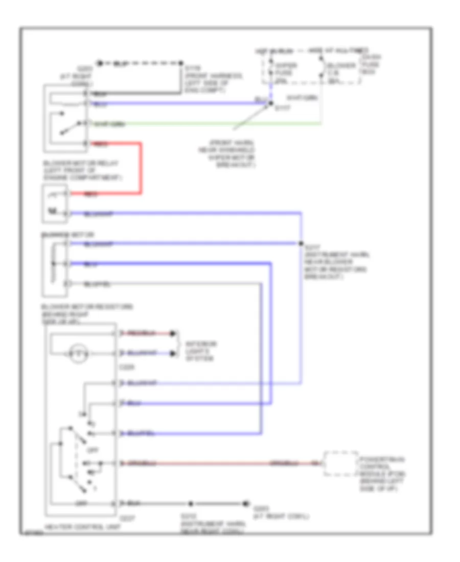
Heater Wiring Diagram for Ford Aspire 1997
List of elements for Heater Wiring Diagram for Ford Aspire 1997:
- (front harn, near winshield wiper motor breakout)
- Blower c.b. 30a
- Blower motor
- Blower motor relay (left front of engine compartment)
- Blower motor resistors (behind right side of i/p)
- C226
- C227
- Dash fuse box
- G203 (at right cowl)
- Heater control unit
- Hot at all times
- Hot in run
- Interior lights system
- Off
- Powertrain control module (pcm) (behind left side of i/p)
- Red
- S117
- S119 (front harness, left side of eng compt)
- S212 (instrument harn, near right cowl)
- S217 (instrument harn, near blower motor resistors breakout)
- Wiper fuse 20a
 English