ENGINE PERFORMANCE
1.3L
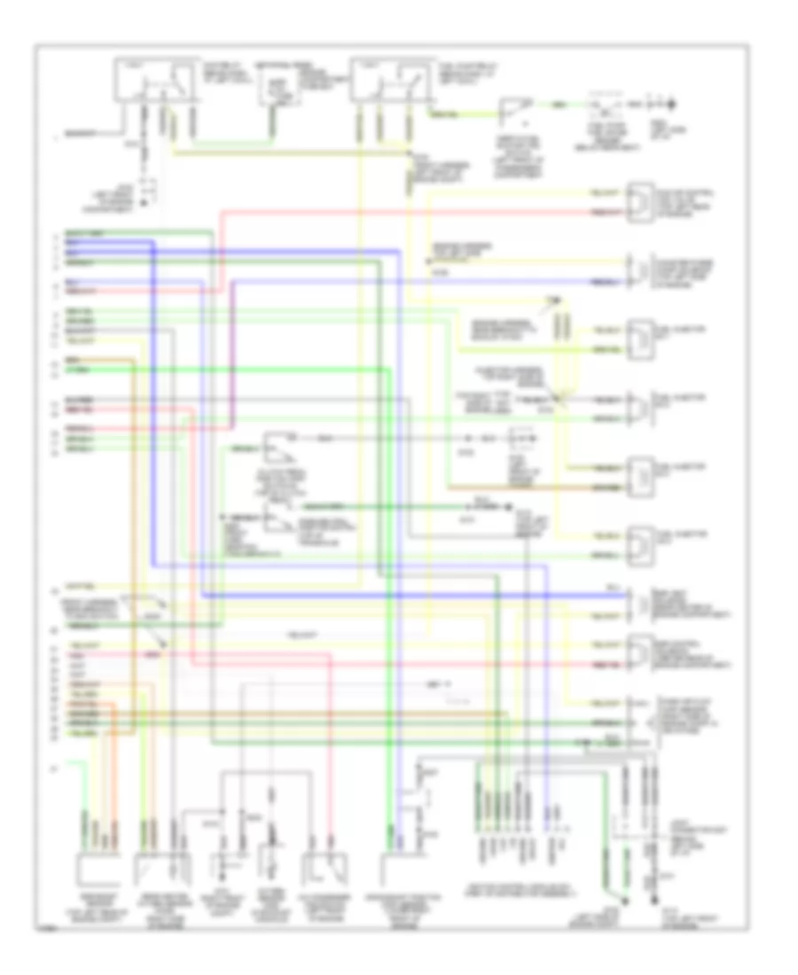
1.3L, Engine Performance Wiring Diagrams (1 of 2) for Ford Aspire 1997

List of elements for 1.3L, Engine Performance Wiring Diagrams (1 of 2) for Ford Aspire 1997:
- (a/t only) psp
- (behind left side of dash) powertrain control module (pcm)
- (eng harness, left front of eng compt)
- (engine harness, near breakout to pcm conn)
- (front harness, near break- out to left side marker lamp)
- (front harness, near break- out to right side marker lp)
- (front harness, near breakout to pcm conn)
- (injector harness, near inj 4 breakout)
- (left side of engine compt)
- (top right side of engine)
- A/t
- Acc
- Acr
- Air conditioning system
- Blmt
- Boo
- Brake on/off (boo) switch (behind dash, top of brake pedal)
- C200
- C201
- C209
- C210
- C257
- Canp
- Ccps
- Cfan
- Cfr
- Cid signal
- Ckp
- Cooling fan system
- Dash fuse box
- Data link connector (dlc) #1 (left side of engine compartment)
- Data link connector (dlc) #2 (left side of eng compt)
- Def
- Defogger system
- Dlc #1
- Dlc #2
- Drl
- Ect
- Egr boost sens
- Egr valve position sensor
- Egrc
- Egrv
- Engine coolant temperature (ect) sensor (top right front of engine)
- Engine fuse 10a
- Evp
- Fpr
- G100 (left front of engine compt)
- G102
- Gnd
- Hdlr
- Head- lights system
- Headlights system
- Hot at all times
- Hot in start or run
- Iac
- Iat
- Idl
- Idle switch (top of engine)
- Ignition switch
- Inj1
- Inj2
- Inj3
- Inj4
- Instrument panel
- Intake air temperature (iat) sensor (right side of engine compartment in air intake)
- Kapwr
- Lock
- M/t
- Maf
- Malfunction indicator lamp
- Meter fuse 15a
- Mil
- Off
- Oxy sens o2s
- Pnk
- Pnp/cpp
- Power steering pressure (psp) switch (lower right front of engine compt)
- Rear h02s
- Rear ho2s
- Red
- Room fuse 10a
- Run
- S104
- S107
- S108
- S109
- S121
- S122
- S127
- S137
- S138
- S200
- S202
- S203 (front harness, near breakout to pcm conn)
- S204
- S246
- S248
- Sigrtn
- Spout
- Start
- Starting system
- Starting system (transmission range switch)
- Stop fuse 15a
- Throttle position (tp) sensor (top rear of engine, on throttle body)
- Vpwr
- Vref
- Vss
- Vst
1.3L, Engine Performance Wiring Diagrams (2 of 2) for Ford Aspire 1997
List of elements for 1.3L, Engine Performance Wiring Diagrams (2 of 2) for Ford Aspire 1997:
- (behind left side of i/p)
- (behnd dash, at left cowl)
- (engine harness, near breakout to backup lp sw)
- (engine harness, top left side of engine)
- (front harness, near breakout to boo switch)
- (injector harness, top right side of engine)
- (not
- (right side of engine)
- (top left rear of engine compt)
- (top right side of engine)
- A/c condenser fan switch (left front of engine)
- C108
- Canister purge (canp) solenoid (top left side of engine)
- Cid
- Ckp
- Clutch pedal position (cpp) switch #1 (top of clutch pedal)
- Crankshaft position (ckp) sensor (lower right
- Dlc
- Egi inj fuse 30a
- Egr boost sensor
- Egr control solenoid (center rear of engine compartment)
- Egr vent solenoid (rear center of engine compartment)
- Engine compartment fuse box
- Engine compt)
- Front of engine)
- Fuel injector no.1
- Fuel injector no.2
- Fuel injector no.3
- Fuel injector no.4
- Fuel pump relay
- Fuel pump/ fuel gauge sender (below rear seat)
- G100 (left front of engine compartment)
- G100 (left front of engine compt)
- G101 (right front of engine compt)
- G102 (left side of engine compt)
- G110 (top left front of engine)
- G202 (left side of i/p)
- Ground
- Hot at all times
- Idle air control (iac) valve (top left rear of engine)
- Ignition
- Ignition control module (icm) (part of distributor assembly)
- Inertia fuel shutoff (ifs) switch (left front of passenger's compartment
- Joint connector c207
- Main relay (behnd dash, at left cowl)
- Mass air flow (maf) sensor (right side of engine compt in air intake)
- Nca
- Oxygen sensor (o2s) (in exhaust manifold)
- Park/neutral position switch (top of transaxle)
- Pnk
- Rear heated oxygen sensor (ho2s)
- S100
- S102
- S103
- S106
- S111
- S122
- S126
- S131
- S143
- S232
- S237
- S249
- S250
- S253 (front harn, near pcm conn breakout)
- Spout
- Used)
- Vpwr