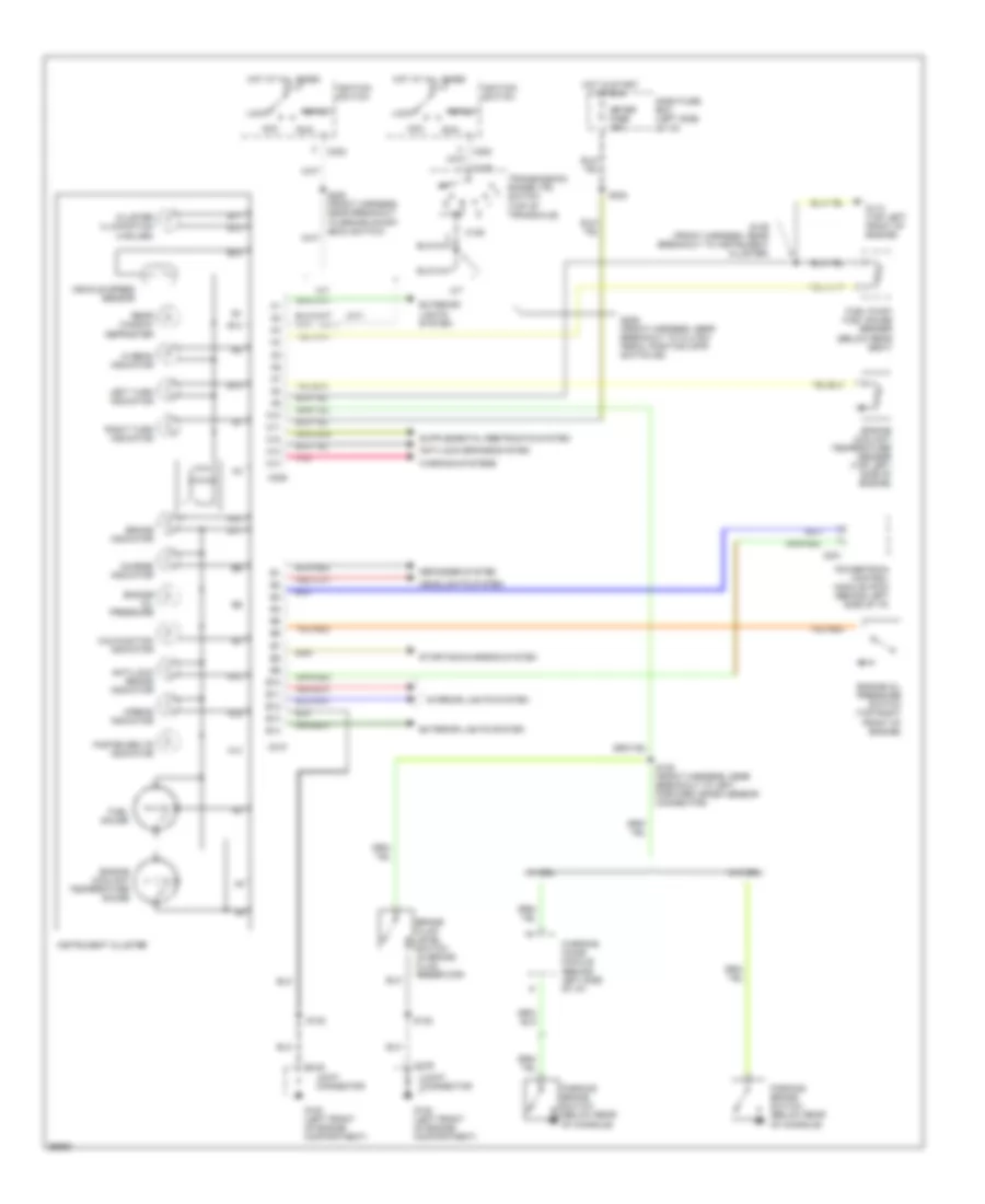
INSTRUMENT CLUSTER
Instrument Cluster Wiring Diagram for Ford Aspire 1997
List of elements for Instrument Cluster Wiring Diagram for Ford Aspire 1997:
- (a/t)
- (m/t)
- A/t
- A10
- A11
- A12
- A13
- A14
- Acc
- Airbag indicator
- Anti-lock brake indicator
- Anti-lock brakes system
- B10
- B11
- B12
- B13
- B14
- Brake fluid level switch (in brake fluid reservoir)
- Brake indicator
- C109
- C129
- C201
- C202
- C209
- C210
- Charge indicator
- Cluster illumination (4 bulbs)
- Dash fuse box (left side of i/p)
- Defogger system
- Engine coolant temperature gauge
- Engine coolant temperature sender (top left side of engine)
- Engine oil pressure
- Engine oil pressure switch (top right front of engine)
- Exterior lights system
- Fasten belts indicator
- Fuel gauge
- Fuel pump/ fuel gauge sender (below rear seat)
- G100 (left front of engine compartment)
- G110 (top left front of engine)
- Headlights system
- Hi beam indicator
- Hot at all times
- Hot in start or run
- Ignition switch
- Instrument cluster
- Interior lights system
- Joint connector
- Left turn indicator
- Lock
- M/t
- Malfunction indicator
- Meter fuse 15a
- Parking brake switch (below rear of console)
- Pnk
- Powertrain control module (pcm) (behind left side of i/p)
- Rear window defroster
- Right turn indicator
- Run
- S122
- S129 (front harness, near breakout to instrument cluster)
- S135 (front harness, near breakout to left forward crash sensor connector)
- S202
- S205 (front harness, near breakout to brake on/off (boo) switch)
- S206 (front harness, near breakout to clutch pedal position (cpp) switch #2)
- Start
- Starting/charging system
- Transmission range (tr) switch (top of transaxle)
- Vehicle speed sensor
- W/ drl
- W/o drl
- Warning chime module (behind left side of i/p)
- Warning systems
 English