AIR CONDITIONING
A/C Wiring Diagram for Pontiac Firebird Trans Am 1995

List of elements for A/C Wiring Diagram for Pontiac Firebird Trans Am 1995:
- (front of left cylinder head)
- (in underhood electrical center)
- (top right side of engine)
- (v6 vin s, v8 vin p)
- +5v
- A/c clutch diode
- A/c compressor clutch
- A/c compressor relay
- A/c cruise fuse 15a
- A/c evaporator temperature sensor (in evaporator core)
- A/c pressure sensor (above right shock tower)
- A/c request
- Bi-lv
- Blend
- Blower motor
- Blower resistors (in hvac module)
- Blower switch
- C tan
- Center
- Clutch status
- Compressor ctrl
- Coolant fan relay 1 (in underhood electrical center)
- Coolant fan relay 2 (in underhood electrical center) (v8 vin p w/c60, v6 vin k)
- Coolant fan relay 3 (in underhood electrical center) (v8 vin p w/c60, v6 vin k)
- Def
- Engine coolant temperature sensor (front of engine)
- Fan control
- Fans/actr fuse 6 10a
- G108 (near top left side of radiator)
- G110 (v8 vin p, v6 vin k) g120 (v6 vin s)
- G200 (left kick panel)
- G203 (right kick panel)
- Heater-a/c control assembly
- High blower relay (under i/p above left side of floor tunnel)
- Hot at all times
- Hot in run
- Hot in run, bulb test or start
- Htr
- Htr-a/c fuse 25a
- I/p fuse block
- Left coolant fan
- Max
- Mode switch
- Nca
- Norm
- Off
- Pnk
- Powertrain control module (in engine compartment, rear of shock tower)
- Probe (inserted in evaporator)
- Red
- Right coolant fan (v8 vin p w/c60, v6 vin k)
- Sensor ground
- Sensor input
- Solid state
- Tan
- Underhood electrical
- Underhood electrical center
- V6 vin k
- V6 vin k v8 vin p w/c60
- V6 vin s
- V6 vin s v8 vin p
- V6 vin s v8 vin p w/c41
- V8 vin p
- Vent
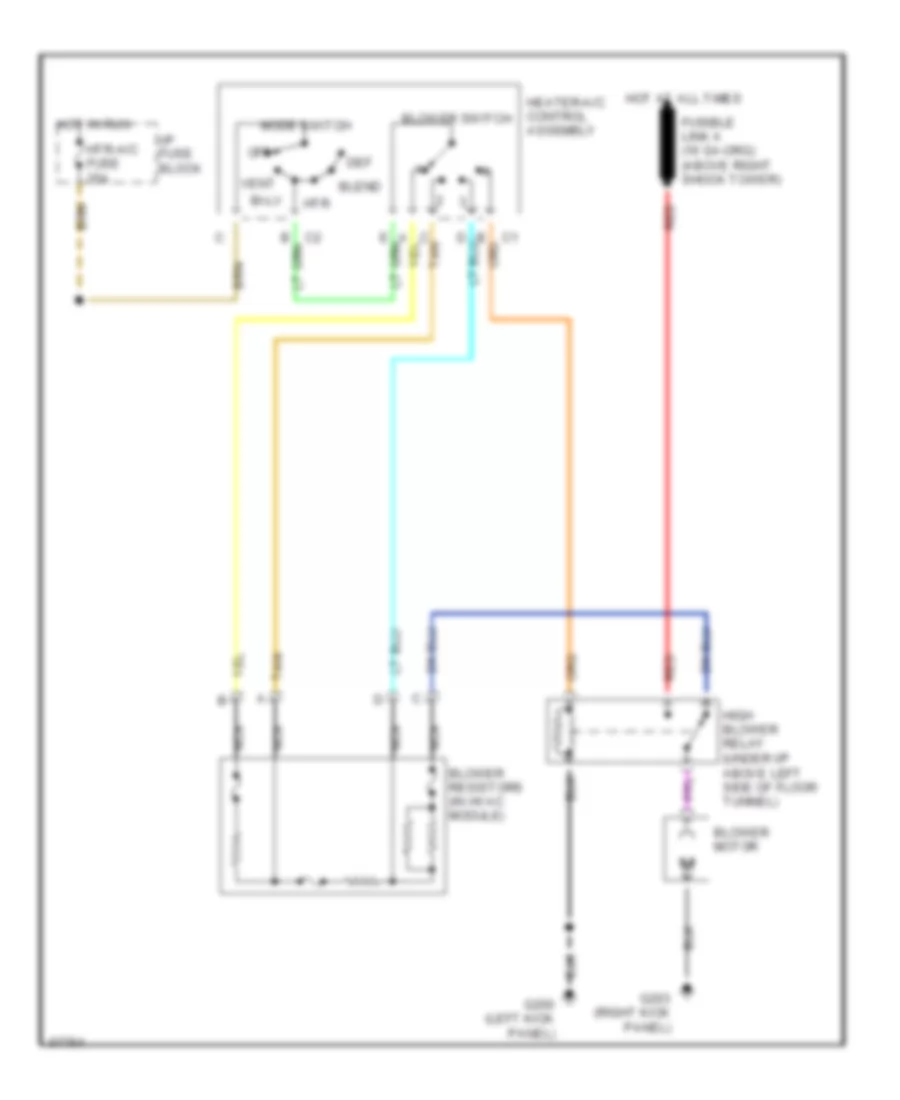
Heater Wiring Diagram for Pontiac Firebird Trans Am 1995
List of elements for Heater Wiring Diagram for Pontiac Firebird Trans Am 1995:
- Bi-lv
- Blend
- Blower motor
- Blower resistors (in hvac module)
- Blower switch
- C tan
- Def
- G200 (left kick panel)
- G203 (right kick panel)
- Heater-a/c control assembly
- High blower relay (under i/p above left side of floor tunnel)
- Hot at all times
- Hot in run
- Htr
- Htr-a/c fuse 25a
- I/p fuse block
- Mode switch
- Nca
- Off
- Red
- Tan
- Vent