COOLING FAN
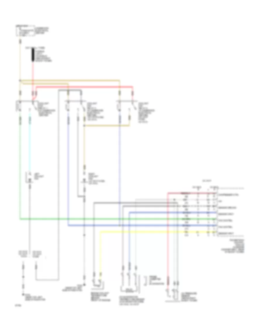
Cooling Fan Wiring Diagram for Pontiac Firebird Trans Am 1995
List of elements for Cooling Fan Wiring Diagram for Pontiac Firebird Trans Am 1995:
- (v6 vin s, v8 vin p)
- +5v
- A/c evaporator temperature sensor (in evaporator core)
- A/c pressure sensor (above right shock tower)
- Compressor ctrl
- Coolant fan relay 1 (in underhood electrical center)
- Coolant fan relay 2 (in underhood electrical center) (v8 vin p w/c60, v6 vin k)
- Coolant fan relay 3 (in underhood electrical center) (v8 vin p w/c60, v6 vin k)
- Engine coolant temperature sensor (front of engine)
- Fan control
- Fans/actr fuse 6 10a
- G108 (near top left side of radiator)
- Hot at all times
- Hot in run
- Left coolant fan
- Powertrain control module (in engine compartment, rear of shock tower)
- Probe (inserted in evaporator)
- Red
- Right coolant fan (v8 vin p w/c60, v6 vin k)
- Sensor ground
- Sensor input
- Solid state
- Underhood electrical center
- V6 vin k
- V6 vin k v8 vin p w/c60
- V6 vin s
- V6 vin s v8 vin p w/c41
- V8 vin p
 English