STARTING/CHARGING
Charging Wiring Diagram for Pontiac Firebird Trans Am 1995

List of elements for Charging Wiring Diagram for Pontiac Firebird Trans Am 1995:
- a13, c14
- a14, c12 red v8 vin k
- a5, d13
- (not used)
- (solid state)
- (v6 vin k)
- *pontiac **chevy
- Ac sense
- Bat
- Batt
- Battery
- C 1995 vftc
- Check gages ind.
- Courtesy fuse 8 10a
- Dc sense
- Field (rotor)
- G103 (top of right shock tower)
- G119 (l32) (lower right front of engine)
- G120 (lt1) (right side of engine block)
- Gages fuse 9 10a
- Generator (right front of engine)
- Hot at all times
- Hot in run, bulb test or start
- I/p fuse block
- Ind. request
- Instrument cluster
- Pnk
- Power distribution
- Powertrain control module (near right shock tower) b
- Rectifier bridge
- Red
- Regulator
- Solid state
- Starter solenoid (bottom of right side of engine, above starter motor)
- Stator
- Turn on input
- V6 vin k
- V6 vin s,
- V6 vin s, v8 vin k
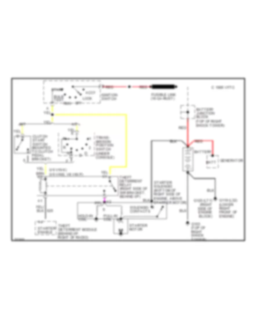
Starting Wiring Diagram for Pontiac Firebird Trans Am 1995
List of elements for Starting Wiring Diagram for Pontiac Firebird Trans Am 1995:
- (top of right shock tower)
- (v6 vin k)
- (v6 vins, v8 vin p)
- A/t
- Accy
- Battery
- Battery junction block
- Bulb test
- C 1995 vftc
- Clutch start switch (mounted to clutch pedal bracket)
- Fusible link (16 ga-rust)
- G103 (top of right shock tower)
- G119 (l32) (lower right front of engine)
- G120 (lt1) (right side of engine block)
- Generator batt
- Hold-in coil
- Ignition switch
- Lock
- M/t
- Off
- Pull-in coil
- Red
- Run
- Solenoid contacts
- Start
- Starter enable
- Starter motor
- Theft deterrent module (behind i/p, right of radio)
- Theft deterrent relay (right side of sir bracket, behind i/p)
- Trans- mission position switch (under console)