AIR CONDITIONING
Automatic A/C Wiring Diagram (1 of 2) for Volvo C70 T-5 2006

List of elements for Automatic A/C Wiring Diagram (1 of 2) for Volvo C70 T-5 2006:
- Air quality sensor (at right side of plenum)
- Climate control module (ccm)
- Climate control system electromagnetic clutch (left front of engine)
- Climate control system relay
- Computer data lines system
- Defroster damper motor module
- Engine compartment distribution box (left side of engine compt, beside strut tower)
- Engine management main relay
- Evaporator temperature sensor (top of hvac housing)
- Floor/ventilation damper motor module (left side of hvac housing)
- Fuse 10a
- Fuse 15a
- Fuse 30a
- Fuse 40a
- Fuse 60a
- G31/10 (right kick panel)
- G31/110 (on right macpherson strut)
- Hot at all times
- Interior temperature sensor (behind left side of dash)
- Left side temperature damper motor module (center of hvac housing)
- Passenger compartment fan motor (behind center of dash)
- Recirculation damper motor module (right side of hvac assembly)
- Red
- Right side temperature damper motor module (center of hvac housing)
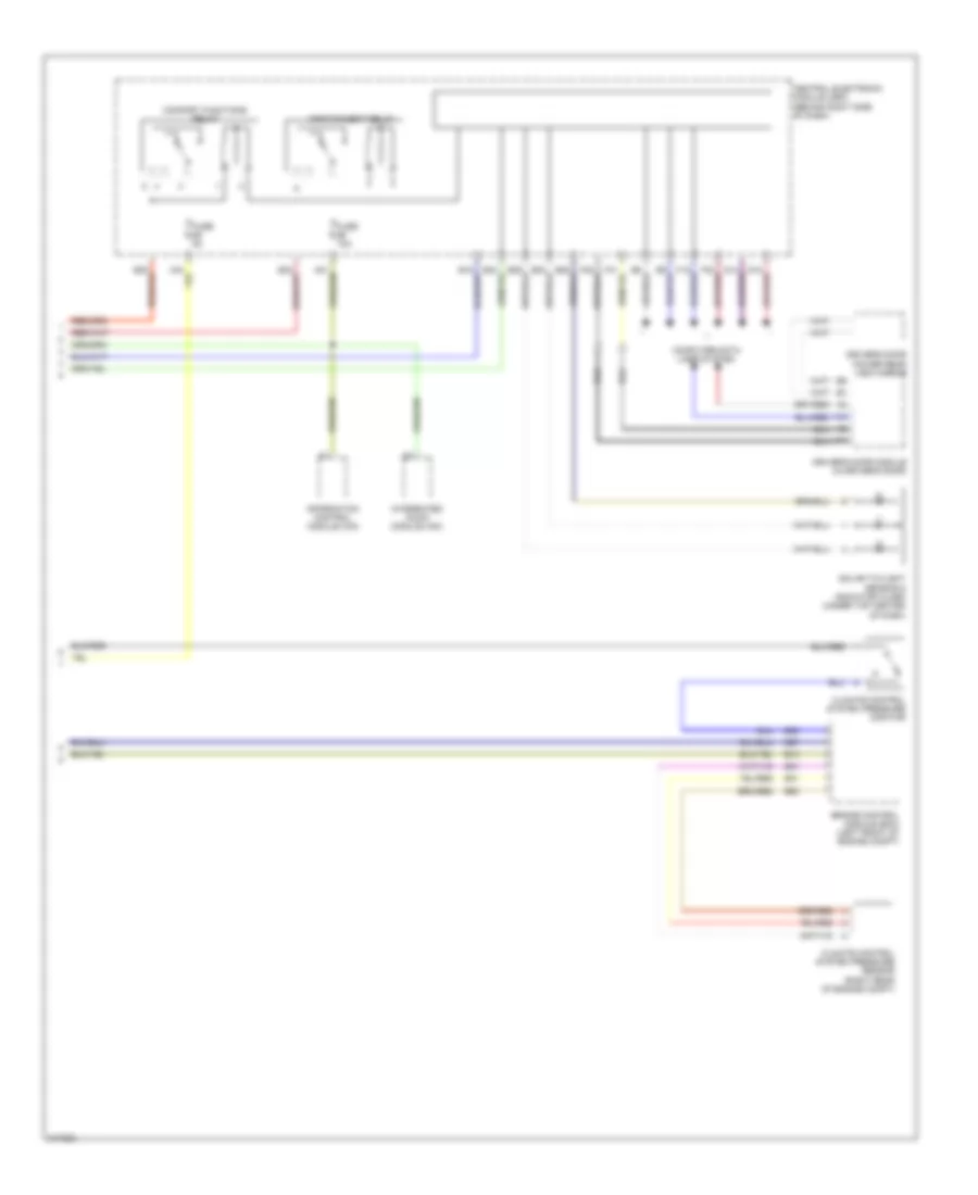
Automatic A/C Wiring Diagram (2 of 2) for Volvo C70 T-5 2006
List of elements for Automatic A/C Wiring Diagram (2 of 2) for Volvo C70 T-5 2006:
- A12
- A17
- B10
- B25
- B27
- B31
- B51
- B53
- Central electronic module (cem) (behind right side of dash)
- Climate control system pressure monitor
- Climate control system pressure sensor (right rear of engine compt)
- Comfort functions relay
- Computer data lines system
- Driver's door module (in driver's door)
- Driver's door power rear view mirror
- Engine control module (ecm) (left front of engine compt)
- Fuse 10a
- Fuse 5a
- Information control module (icm)
- Infotainment relay
- Integrated audio module (iam)
- Solar twilight sensor & indicator alarm (under top center of dash)
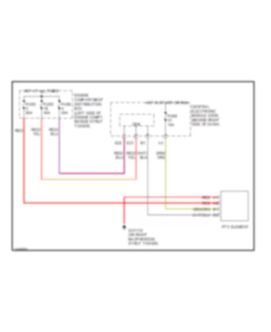
Auxiliary Heater Wiring Diagram for Volvo C70 T-5 2006
List of elements for Auxiliary Heater Wiring Diagram for Volvo C70 T-5 2006:
- Cem
- Central electronic module (cem) (behind right side of dash)
- E21
- E22
- Engine compartment distribution box (left side of engine compt, beside strut tower)
- Fuse 10a
- Fuse 40a
- Fuse 60a
- Fuse 80a
- G31/112 (on right macpherson strut tower)
- Hot at all times
- Hot in start or run
- Ptc element
- Red