STARTING/CHARGING
Charging Wiring Diagram for Volvo C70 T-5 2006

List of elements for Charging Wiring Diagram for Volvo C70 T-5 2006:
- A10
- A46
- B41
- B44
- B54
- B57
- Battery
- Battery temperature sensor (in battery tray)
- Central electronic module (behind left side of dash)
- Climate control module
- Computer data lines system
- Driver information module
- Fusible link pf1 150a
- G13
- G14
- G15
- G31/3 (on left macpherson strut tower)
- G31/4 (left side of eng compt)
- Generator
- Information control module
- Instrument cluster
- Power distribution system
- Red
- Starter motor
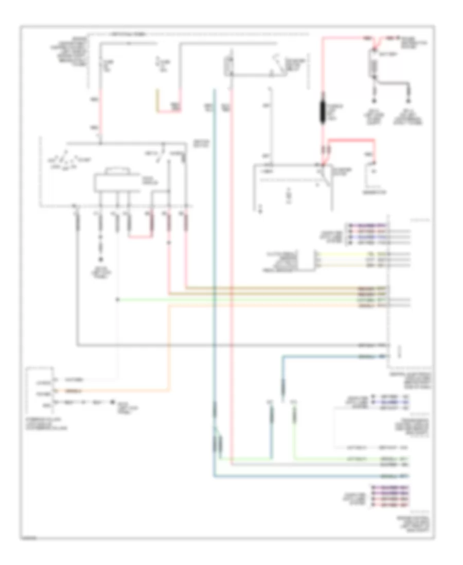
Starting Wiring Diagram for Volvo C70 T-5 2006
List of elements for Starting Wiring Diagram for Volvo C70 T-5 2006:
- (a/t only)
- A/t
- A15
- A42
- Acc
- B10
- B11
- B13
- B17
- B41
- B44
- B54
- B57
- Battery
- Central electronic module (cem) (behind right side of dash)
- Clutch pedal sensor (m/t only) (on clutch pedal bracket)
- Computer data lines system
- Engine compartment distribution box (left side of engine compt, beside strut tower)
- Engine control module (ecm) (left front of eng compt)
- F14
- F16
- Fuse 15a
- Fuse 30a
- Fusible link pf1 150a
- G12
- G14
- G15
- G21
- G23
- G31/3 (on left macpherson strut tower)
- G31/4 (left side of eng compt)
- G31/6 (left kick panel)
- G31/83 (left kick panel)
- Generator
- Gnd
- Hot at all times
- Ignition switch
- Inhibit
- Key-in
- Lin bus
- Lock
- M/t
- Off
- Pats module
- Power
- Power distribution system
- Red
- Start
- Starter motor
- Starter motor relay
- Steering column lock module (in steering column)
- Transmission control module (center rear of eng compt)