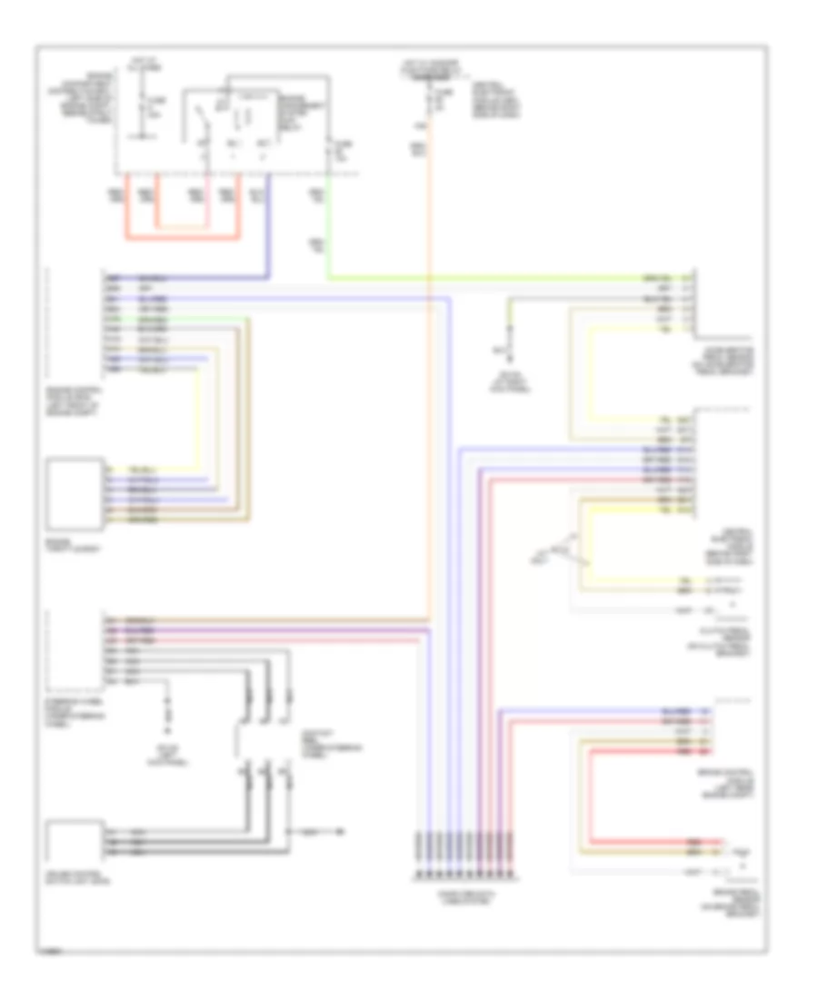
CRUISE CONTROL
Cruise Control Wiring Diagram for Volvo C70 T-5 2006
List of elements for Cruise Control Wiring Diagram for Volvo C70 T-5 2006:
- A19
- A40
- A45
- A65
- A74
- A75
- A88
- Accelerator pedal sensor (on accelerator pedal bracket)
- B2 nca
- B26
- B27
- B3 nca
- B41
- B5 nca
- B54
- Brake control module (left rear engine compt)
- Brake pedal sensor (on brake pedal bracket)
- Central electronic module (behind right side of dash)
- Central electronic module (cem) (behind right side of dash)
- Clutch pedal sensor (on clutch pedal bracket)
- Computer data lines system
- Contact reel (under steering wheel)
- Cruise control switch unit (sws)
- Engine compartment distribution box (left side of engine compt, beside strut tower)
- Engine control module (ecm) (left front of engine compt)
- Engine management system main relay
- Engine throttle body
- F14
- F15
- Fuse 10a
- Fuse 30a
- Fuse 5a
- G12
- G14
- G15
- G21
- G22
- G23
- G31
- G31/83 (left kick panel)
- G31/84 (at right kick panel)
- Hot at all times
- Hot w/ comfort functions relay energized
- M/t only
- Nca
- Red
- Steering wheel module (under steering wheel)
 English