ANTI-LOCK BRAKES
Anti-lock Brakes Wiring Diagram (1 of 3) for Audi Q5 Premium Plus 2014

List of elements for Anti-lock Brakes Wiring Diagram (1 of 3) for Audi Q5 Premium Plus 2014:
- (not used)
- 40a
- Abs control module (integral to abs hydraulic unit)
- Abs control module fuse 1
- Abs hydraulic pump
- Auto hold button
- Computer data lines system
- Electro-mechanical parking brake button
- Fuse 10a
- Fuse 110a
- Fuse 5a
- Fuse carrier 1
- Fuse carrier 2
- Fuse panel a (on battery positive terminal)
- Fuse panel c (left end of dash)
- G671 (on lower left front long member)
- Hot at all times
- Left front abs wheel speed sensor (on left front brake hub)
- Left rear abs wheel speed sensor (on left rear brake hub)
- Red
- Roof rack recognition sensor (part of left roof railing)
- T17d
- T2ax
- Valve 1 pressure switch regulation high driving dynamics
- Valve 1 regulation switch driving dynamics
- Valve 2 pressure switch regulation high driving dynamics
- Valve 2 regulation switch driving dynamics
- Valve abs inlet left front
- Valve abs inlet left rear
- Valve abs inlet right front
- Valve abs inlet right rear
- Valve abs outlet left front
- Valve abs outlet left rear
- Valve abs outlet right front
- Valve abs outlet right rear
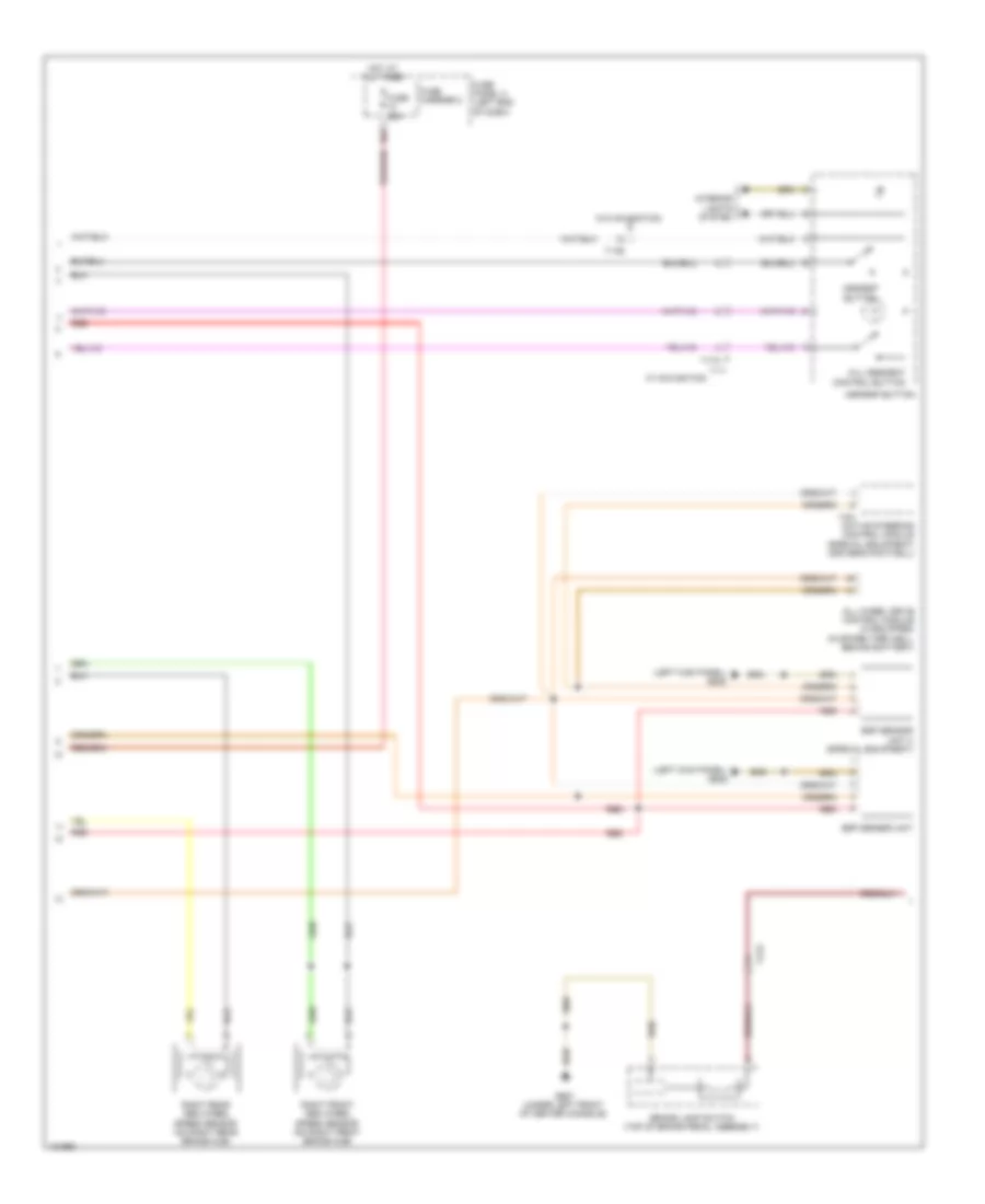
Anti-lock Brakes Wiring Diagram (2 of 3) for Audi Q5 Premium Plus 2014
List of elements for Anti-lock Brakes Wiring Diagram (2 of 3) for Audi Q5 Premium Plus 2014:
- (left kick panel) g639
- 10a
- Active steering control module (special equipment) (driver's footwell)
- All wheel drive control module (if equipped) (in spare tire well, behind battery)
- Asr/esp button
- Brake lamp switch (top of brake pedal assembly)
- Esp sensor unit
- Esp sensor unit 2 (special equipment)
- Fuse 25a
- Fuse carrier 2
- Fuse panel c (left end of dash)
- G687 (under left front of center console)
- Hill descent control button
- Hot at all times
- I10h
- Interior lights system
- Red
- Right front abs wheel speed sensor (on right front brake hub)
- Right rear abs wheel speed sensor (on right rear brake hub)
- T17c
- T17e
- W/ navigation
- W/o navigation
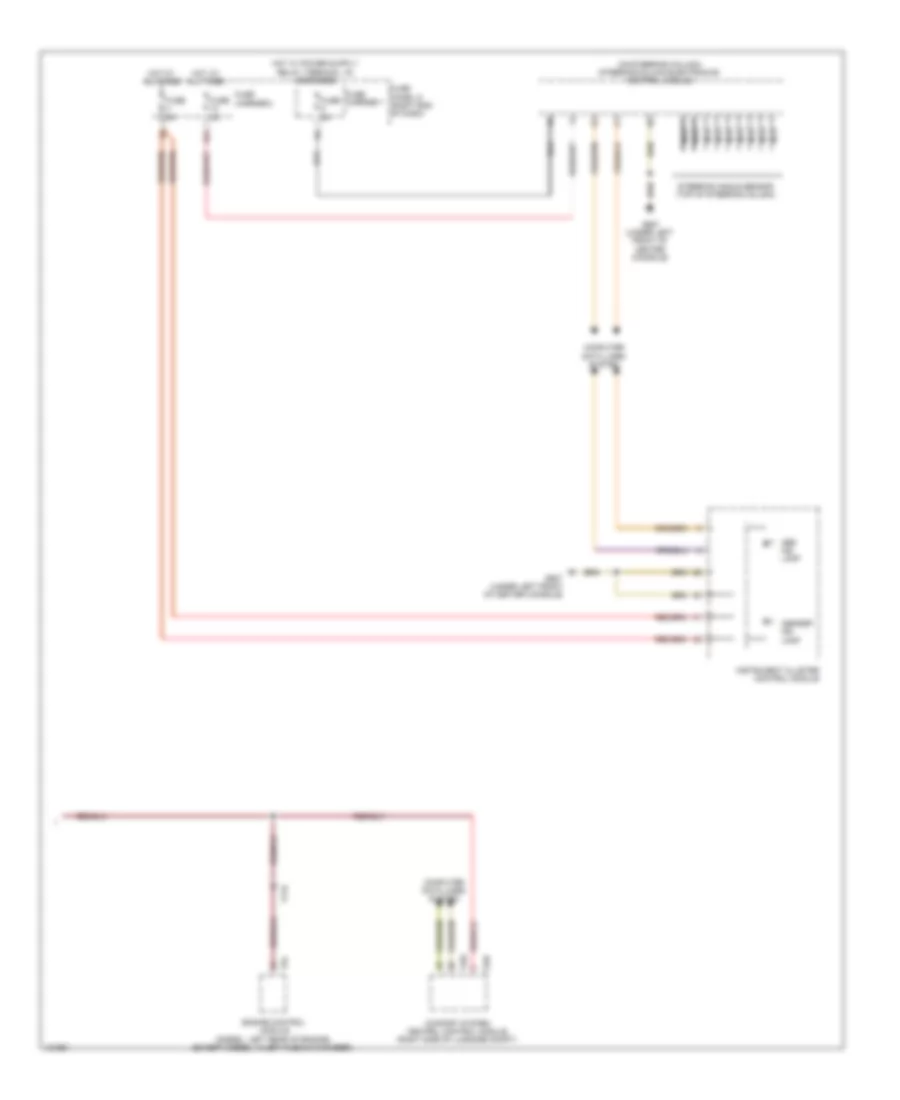
Anti-lock Brakes Wiring Diagram (3 of 3) for Audi Q5 Premium Plus 2014
List of elements for Anti-lock Brakes Wiring Diagram (3 of 3) for Audi Q5 Premium Plus 2014:
- (on steering column) steering column electronics control module
- Abs ind lamp
- Asr/esp ind lamp
- Comfort system central control module (right side of luggage compt)
- Computer data lines system
- Engine control module (diesel: left rear of engine) (except diesel: in left plenum chamber)
- Fuse 5a
- Fuse carrier 1
- Fuse carrier 2
- Fuse panel d (right end of dash)
- G687 (under left front of center console)
- Hot at all times
- Instrument cluster control module
- Nca
- Steering angle sensor (top of steering column)
- T17r
- T32c
- T32d
- T94