TRANSMISSION
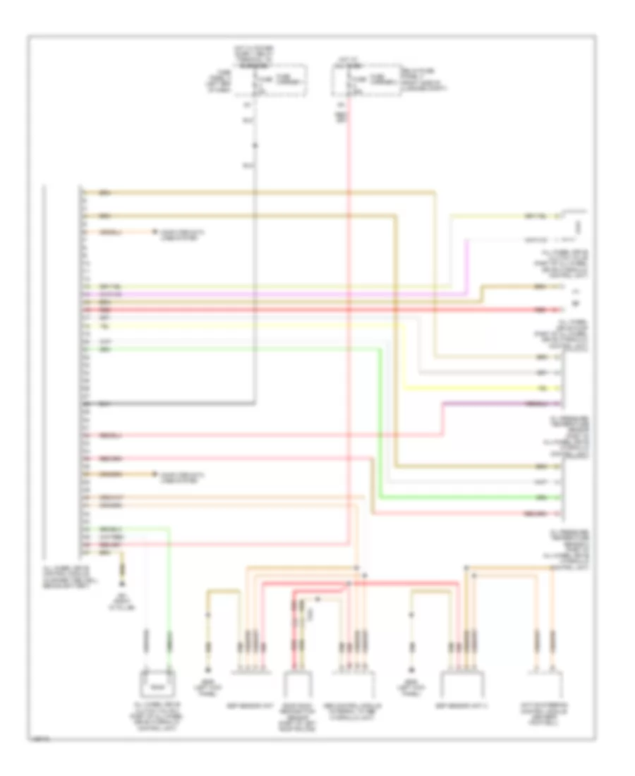
A/T Wiring Diagram (1 of 2) for Audi Q5 Premium Plus 2014

List of elements for A/T Wiring Diagram (1 of 2) for Audi Q5 Premium Plus 2014:
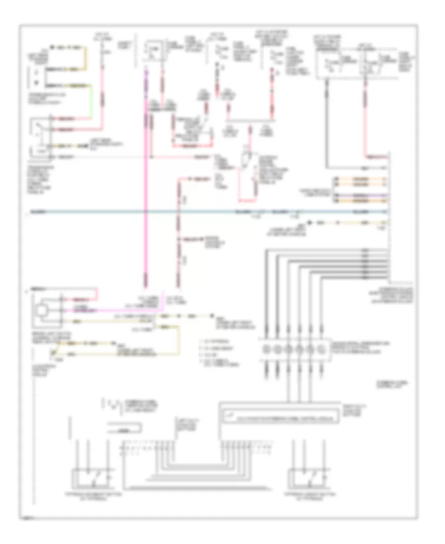
A/T Wiring Diagram (2 of 2) for Audi Q5 Premium Plus 2014
List of elements for A/T Wiring Diagram (2 of 2) for Audi Q5 Premium Plus 2014:
AWD Wiring Diagram for Audi Q5 Premium Plus 2014
List of elements for AWD Wiring Diagram for Audi Q5 Premium Plus 2014: