ELECTRONIC POWER STEERING
Active Steering Control Module Wiring Diagram for Audi Q5 Premium Plus 2014

List of elements for Active Steering Control Module Wiring Diagram for Audi Q5 Premium Plus 2014:
- Active steering control module (driver's footwell)
- Anti-lock brakes system
- Computer data lines system
- Electromechanical power steering motor
- Fuse 35a
- Fuse 5a
- Fuse carrier
- Fuse panel c (left end of dash)
- G602 (left side of driver's footwell)
- G639 (left kick panel)
- Hot at all times
- T10h
- T17b
- T17e
- T2bb
- T4r
- T5d
- T6ar
- T8g
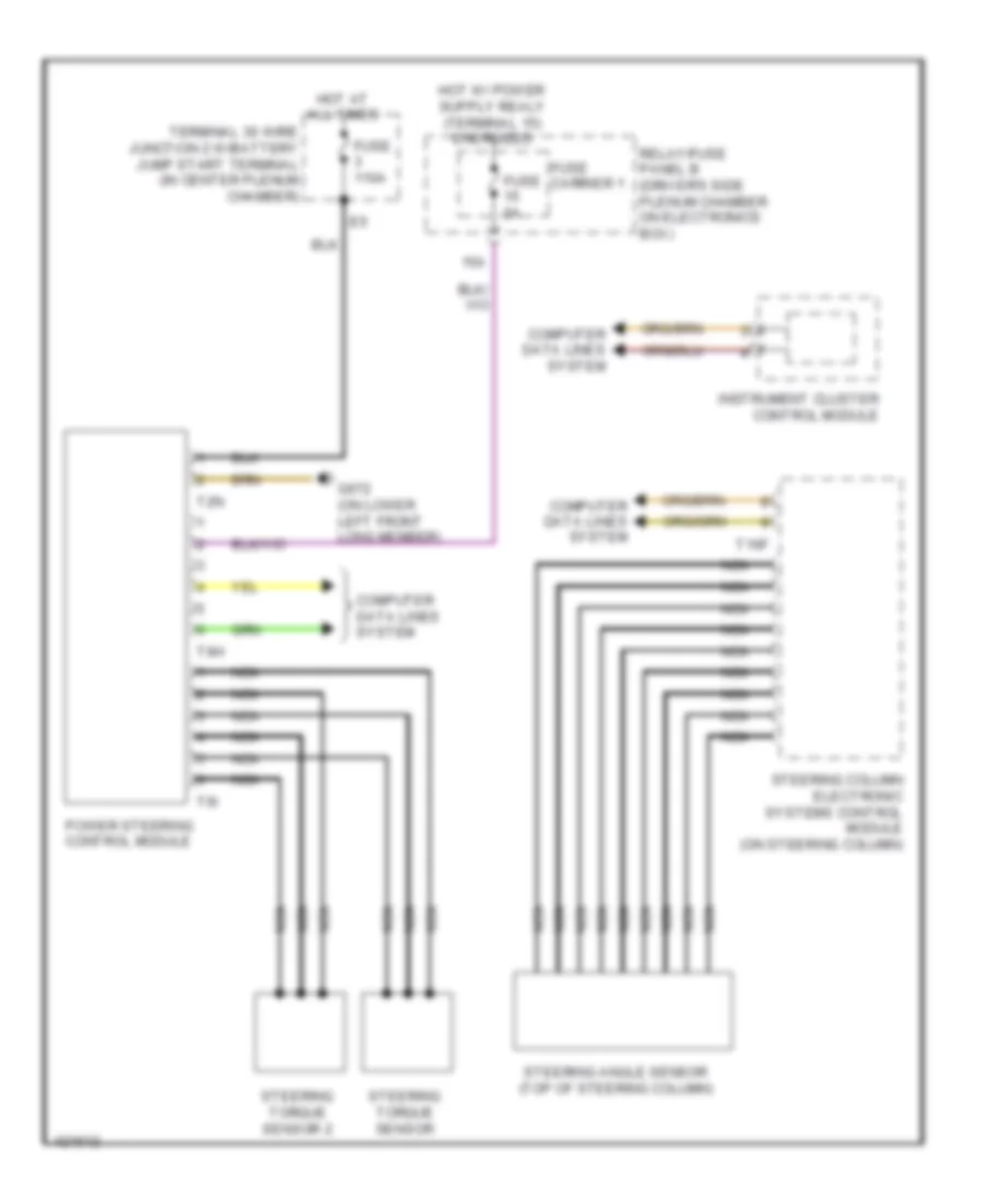
Electromechanical Power Steering Wiring Diagram for Audi Q5 Premium Plus 2014
List of elements for Electromechanical Power Steering Wiring Diagram for Audi Q5 Premium Plus 2014:
- 15a
- Computer data lines system
- Fuse 110a
- Fuse 5a
- Fuse carrier 1
- G672 (on lower left front long member)
- Hot at all times
- Instrument cluster control module
- Nca
- Power steering control module
- Relay/fuse panel b (driver's side plenum chamber on electronics box)
- Steering angle sensor (top of steering column)
- Steering column electronic systems control module (on steering column)
- Steering torque sensor
- Steering torque sensor 2
- T16f
- T2n
- T6h
- T6i
- Terminal 30 wire junction 2 w/battery jump start terminal (in center plenum chamber)
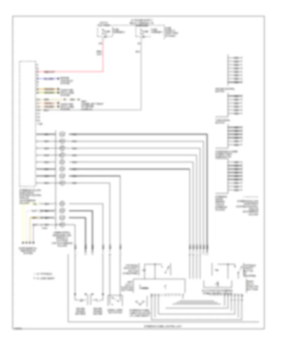
Steering Column Electronic Systems Control Module Wiring Diagram for Audi Q5 Premium Plus 2014
List of elements for Steering Column Electronic Systems Control Module Wiring Diagram for Audi Q5 Premium Plus 2014:
- 12a
- Airbag spiral spring/return spring w/ slip ring (top of steering column)
- Computer data lines system
- Cruise control switch
- Driver air bag igniter
- Driver air bag igniter 2
- Engine controls system
- Fuse 5a
- Fuse carrier 1
- Fuse carrier 2
- Fuse panel d (right end of dash)
- G687 (under left front of center console)
- Hot at all times
- Left multi- function buttons
- Mode
- Multi-function steering wheel control module
- Nca
- Right multi- function buttons
- Signal horn activation
- Steering angle sensor (top of steering column)
- Steering column electronic systems control module (on steering column)
- Steering wheel control unit
- Steering wheel vibration motor (w/ lane assist)
- T16f
- T4ac
- Tiptronic down shift button (if equipped)
- Tiptronic upshift button (if equipped)
- Turn signal switch
- W/ lane assist
- W/ tiptronic
- Windshield wiper intermittent mode switch