ANTI-LOCK BRAKES
Anti-lock Brakes Wiring Diagram (1 of 2) for Mercedes-Benz CLA250 2014

List of elements for Anti-lock Brakes Wiring Diagram (1 of 2) for Mercedes-Benz CLA250 2014:
- (left front footwell) w15/2
- 12v +
- 30g
- 5v +
- Abs ind
- Bls h
- Bls l
- Brake system warning lamp ind
- Can e h
- Can e l
- Computer data lines system
- Electronic stability program control unit (left front of engine compt)
- Engine compartment fuse & relay module (left side engine compt)
- Esp warning lamp ind
- Espa/asr off warning lamp ind
- Fehlende informationen
- Fuse 10a
- Fuse 25a
- Fuse 40a
- Fuse 5a
- Gnd
- Hot at all times
- Hot w/ circuit 15 relay energized
- Hot w/ circuit 30g relay energized
- Instrument cluster
- Parking brake ind
- S12
- Sig
- Stop lamp switch (top of brake pedal assembly)
- Vehicle interior fuse box (right front footwell)
- W70 (left front wheelwell)
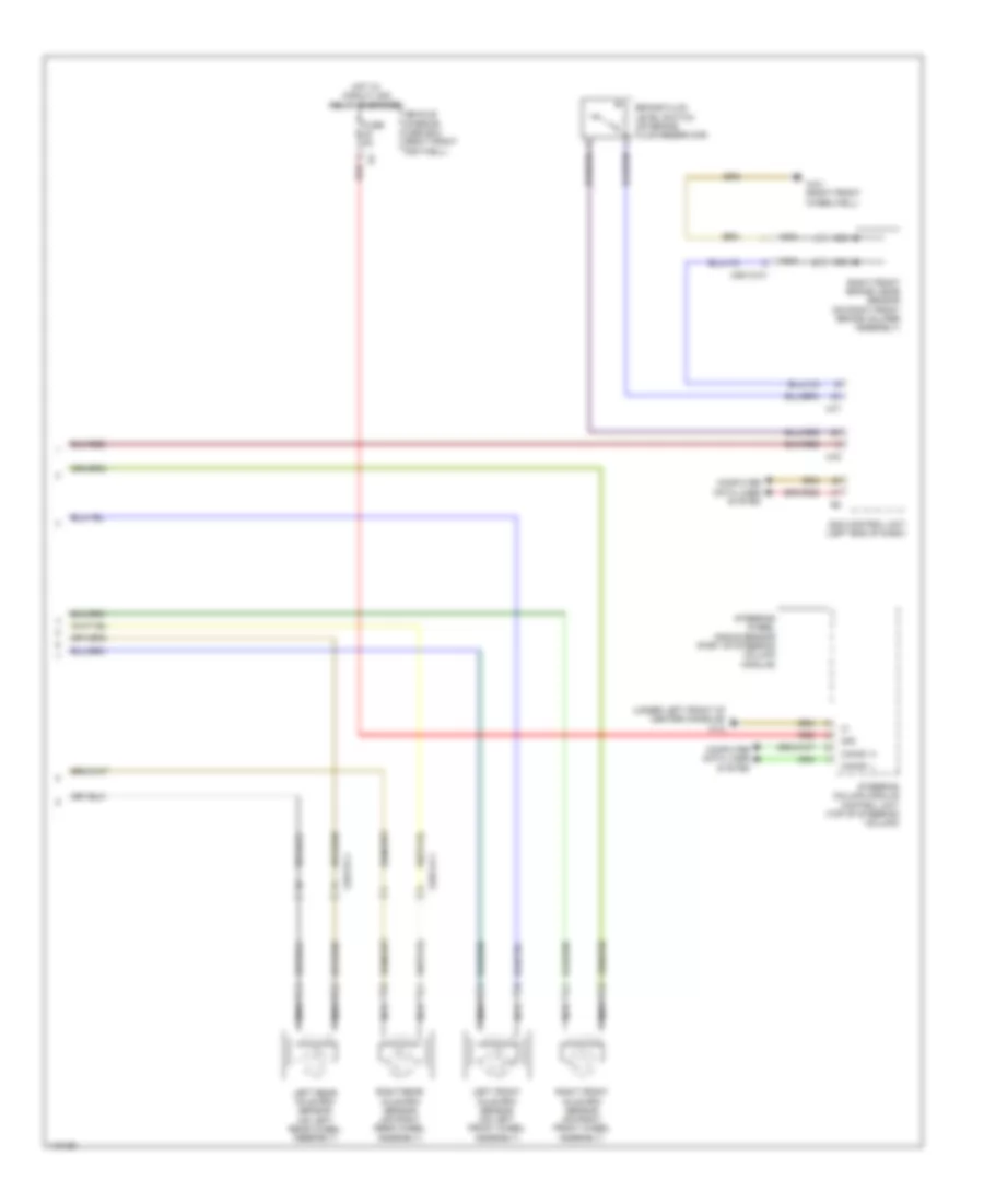
Anti-lock Brakes Wiring Diagram (2 of 2) for Mercedes-Benz CLA250 2014
List of elements for Anti-lock Brakes Wiring Diagram (2 of 2) for Mercedes-Benz CLA250 2014:
- (under left front of center console) w12
- 30g
- Brake fluid level switch (on brake fluid reservoir)
- Can e1 h
- Can e1 l
- Computer data lines system
- Fuse 5a
- Hot w/ circuit 30g relay energized
- Left front axle rpm sensor (on left front wheel assembly)
- Left rear axle rpm sensor (on left rear wheel assembly)
- Nca
- Red
- Right front axle rpm sensor (on right front wheel assembly)
- Right front brake wear sensor (on right front brake caliper assembly)
- Right rear axle rpm sensor (on right rear wheel assembly)
- Sam control unit (left end of dash)
- Steering column module control unit (top of steering column)
- Steering wheel angle sensor (part of steering column module)
- Uh1
- Uh2
- Vehicle interior fuse box (right front footwell)
- W3/1 (right front wheelwell)
- X25/13-c1
- X25/14-c1
- X88/12-c1