HORN
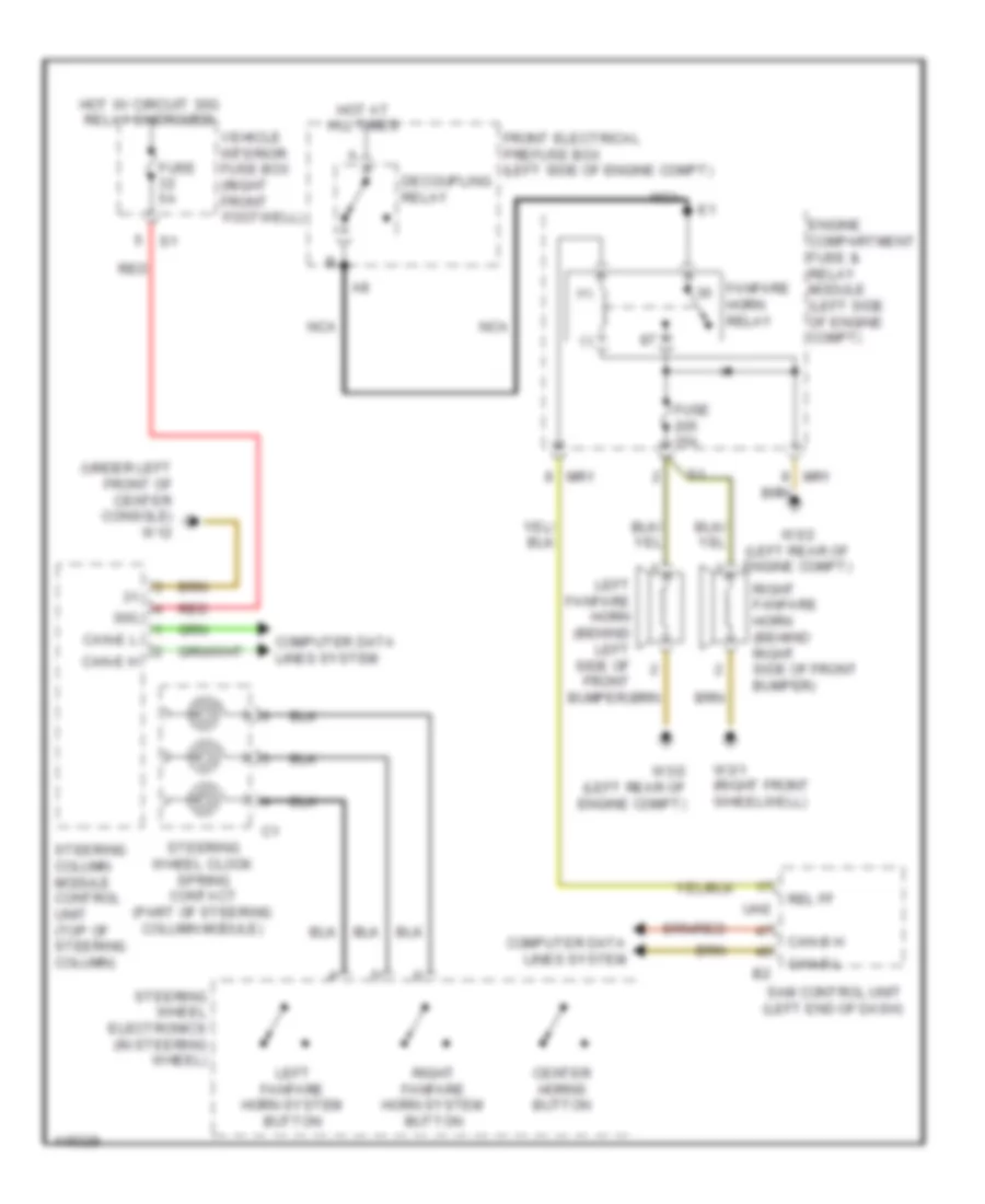
Horn Wiring Diagram for Mercedes-Benz CLA250 2014
List of elements for Horn Wiring Diagram for Mercedes-Benz CLA250 2014:
- (+)
- (-)
- (under left front of center console) w12
- 30g
- Button
- Can-b h
- Can-b l
- Can-e h
- Can-e l
- Center horns button
- Computer data lines system
- Decoupling relay
- Engine compartment fuse & relay module (left side of engine compt)
- Fanfare horn relay
- Front electrical prefuse box (left side of engine compt)
- Fuse 15a
- Fuse 5a
- Hot at all times
- Hot w/ circuit 30g relay energized
- Left fanfare horn (behind left side of front bumper)
- Left fanfare horn system
- Mr1
- Nca
- Red
- Rel ff
- Right fanfare horn (behind right side of front bumper)
- Right fanfare horn system
- Sam control unit (left end of dash)
- Steering column module control unit (top of steering column)
- Steering wheel clock spring contact (part of steering column module)
- Steering wheel electronics (in steering wheel)
- Uh2
- Vehicle interior fuse box (right front footwell)
- W3/1 (right front wheelwell)
- W3/2 (left rear of engine compt)
 English