POWER DISTRIBUTION
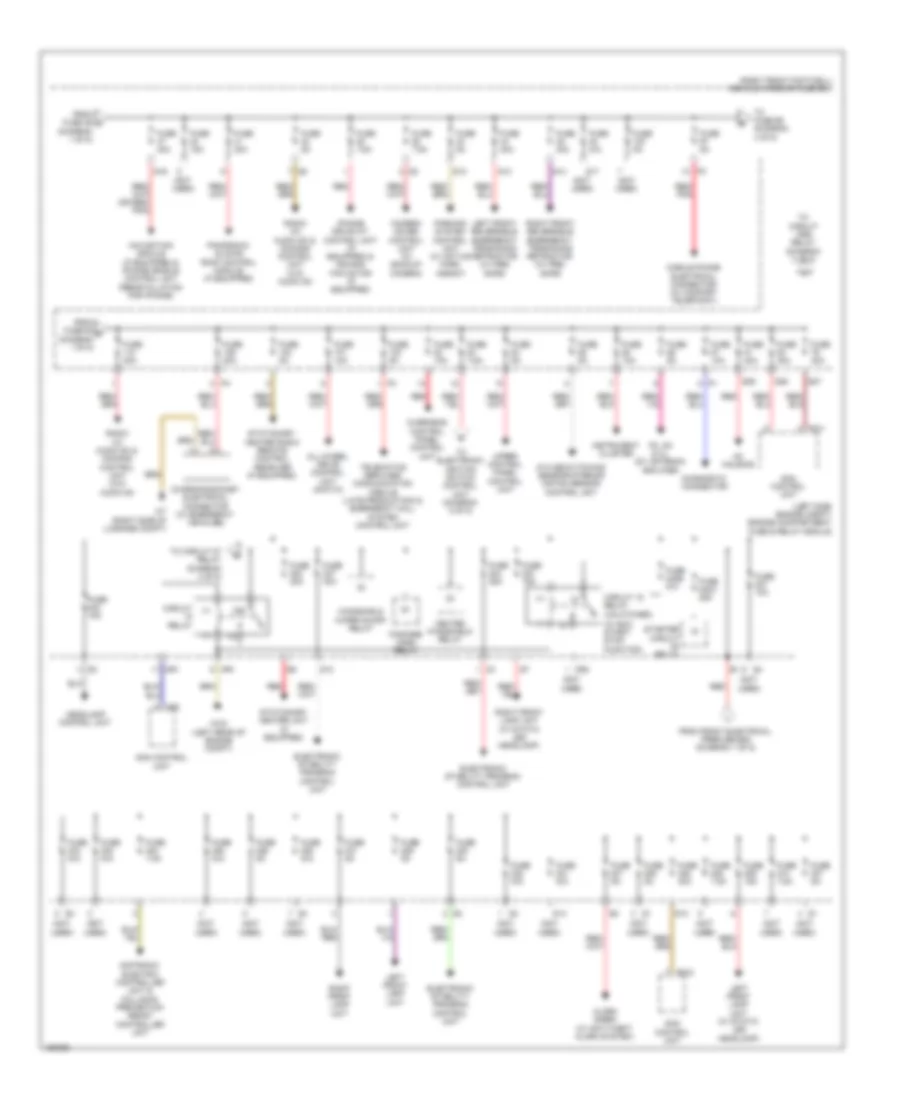
Power Distribution Wiring Diagram (1 of 5) for Mercedes-Benz CLA250 2014

List of elements for Power Distribution Wiring Diagram (1 of 5) for Mercedes-Benz CLA250 2014:
- (left side of engine compt) front electrical prefuse box
- (not used)
- (right front footwell) vehicle interior fuse box
- 85a
- 85b
- 86a
- 86b
- Alternator
- Audio/ comand control panel
- Audio/ comand display
- Automatic air conditioning control & operating unit
- Battery sensor
- Circuit 30g relay
- Decoupling relay
- Driver seat control unit (w/ memory)
- Driver seat lumbar support adjustment control unit (if equipped) & driver seat control unit (w/ memory)
- Eco start/ stop function additional battery relay
- Electric parking brake control unit
- Electrical power steering control unit
- Fan motor
- Front passenger seat control unit
- Front passenger seat control unit (if equipped)
- Fuel pump control unit
- Fuse 100a
- Fuse 10a
- Fuse 125a
- Fuse 150a
- Fuse 200a
- Fuse 200a (or 250a)
- Fuse 20a
- Fuse 25a
- Fuse 300a
- Fuse 30a
- Fuse 40a
- Fuse 5a
- Fuse 7.5a
- Fuse 7.5a (or 5a)
- Fuse 70a
- Fuse 80a
- Fuse n/a
- Left front door control unit
- On board electrical system battery
- Overhead control panel control unit
- Ptc heater booster (if equipped)
- Pw2
- Pyrofuse (on battery positive (+) post)
- Red
- Right front door control unit
- S10
- S15
- S18
- S19
- S20
- S21
- S22
- S23
- S24
- S25
- S26
- Sam control unit
- Sound system amplifier control unit (if equipped)
- Starter
- Steering column module control unit
- Telematics services communication module (early production) & keyless-go control unit (if equipped)
- To engine compartment fuse & relay module (diagram 2 of 5)
- To engine compartment fuse & relay module (diagram 3 of 5)
- To fuse 110 (diagram 2 of 5)
- To fuse 26 (diagram 5 of 5)
- To fuse 47 (diagram 2 of 5)
- Trailer recognition control unit (if equipped)
- Trunk lid/lift gate control unit
- Uh1
- W10 (left side of engine compt)
- W3/2 (left rear of engine compt)
- X25/14-c1
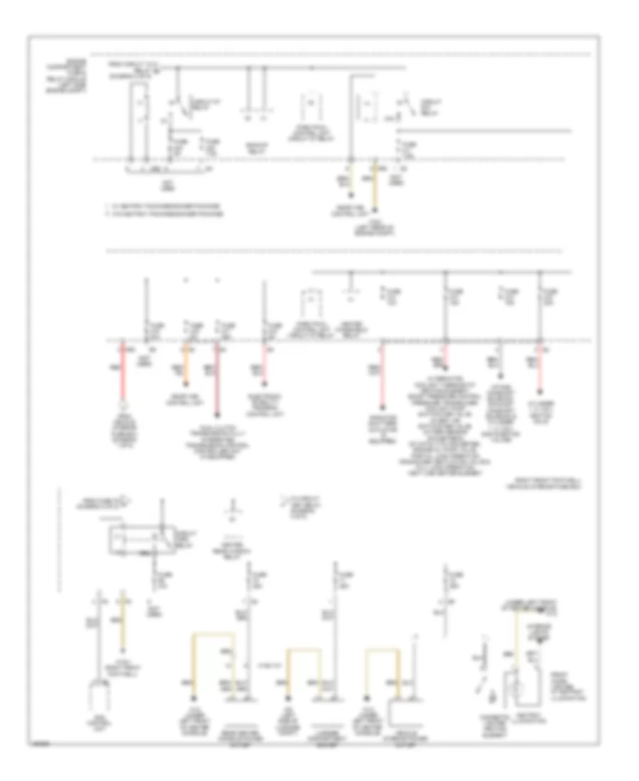
Power Distribution Wiring Diagram (2 of 5) for Mercedes-Benz CLA250 2014
List of elements for Power Distribution Wiring Diagram (2 of 5) for Mercedes-Benz CLA250 2014:
- (+)
- (-)
- (diagram 1 of 5)
- (left side engine compt) engine compartment fuse & relay module
- (not used)
- (right front footwell) vehicle interior fuse box
- (w/ eco start/ stop function)
- 30z
- Ac housing
- Alarm siren (w/ anti-theft alarm system)
- All-wheel drive control unit (4matic)
- Ata (edw)/towing sensor/interior motion sensor control unit
- Camera cover control unit (w/ backup camera)
- Charging socket electrical connector (w/ emergency vehicles)
- Circuit 15 relay (unlatched)
- Circuit relay
- Diagnostic connector
- Distronic electric controller unit & collision prevention assist controller unit
- Electronic stability program control unit
- Fanfare horn relay
- Fm, am & cl (zv) antenna amplifier
- From front electrical prefuse box (diagram 1 of 5)
- From fuse 46 c
- From fuse 63 d (diagram 1 of 5)
- Fuse 10a
- Fuse 15a
- Fuse 20a
- Fuse 240a 25a
- Fuse 240b n/a
- Fuse 25a
- Fuse 30a
- Fuse 40a
- Fuse 5a
- Fuse 7.5a
- Fuse n/a
- Headlamp control unit
- Heated windshield relay
- Instrument cluster
- Iphone drive kit control unit (if equipped) & comand fan motor (if equipped)
- Left front lamp unit
- Left front lamp unit (w/ static led headlamp)
- Left front reversible emergency tensioning retractor (w/ pre- safe)
- Mobile phone electrical connector (w/ comfort telephony)
- Mr1
- Mr2
- Navigation module (if equipped) & iphone cradle control unit (reinstallation for iphone)
- Overhead control panel control unit
- Panoramic sliding roof control module (if equipped)
- Parking system control unit (w/ active park assist)
- Pw1
- Pw2
- Radio (w/ audio 20) & comand control unit (w/o audio 20)
- Red
- Red/ pnk
- Right front lamp unit
- Right front lamp unit (w/ static led headlamp)
- Right front reversible emergency tensioning retractor (w/ pre- safe)
- S12
- S13
- S14
- S16
- S17
- S27
- S28
- S29
- Sam control unit
- Starter circuit relay
- Stationary heater radio remote control receiver (if equipped)
- Stationary heater unit (if equipped)
- Telematics services communication module (late production) & emergency call system control unit
- To circuit 15r2 relay (diagram 3 of 5)
- To circuit 87 relay (diagram 3 of 5)
- To electronic ignition switch control unit (diagram 5 of 5)
- To fuse 99 (diagram 4 of 5)
- Uh2
- Upper control panel control unit
- W3/2 (left rear of engine compt)
- W7 (right side of luggage compt)
- Windshield wiper on/off relay
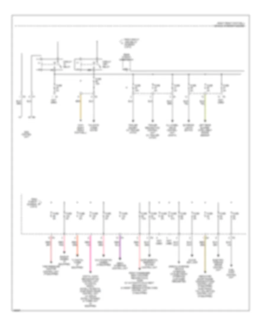
Power Distribution Wiring Diagram (3 of 5) for Mercedes-Benz CLA250 2014
List of elements for Power Distribution Wiring Diagram (3 of 5) for Mercedes-Benz CLA250 2014:
- (+)
- (-)
- (not used)
- (right front footwell) vehicle interior fuse box
- (under left front of center console) w12
- 15r2
- 87m
- Alternator, coolant thermostat heating element, boost pressure control pressure transducer, coolant pump switchover valve, divert air switchover valve, oxygen sensor downstream of catalytic converter, engine oil pump valve, partial load operation crankcase ventilation valve & full load operation vent line heater element
- Ashtray illumination
- Backup relay
- Cigarette lighter heating element
- Circuit 15r2 relay
- Circuit 87 relay
- Circuit 87m relay
- Cylinder 1, 2, 3 & 4 ignition coils
- Dual clutch transmission fully integrated transmission control controller unit (if equipped)
- Electronic stability program control unit
- Engine compartment fuse & relay module (left side engine compt)
- From circuit 15 relay b (diagram 2 of 5)
- From fuse 79 h (diagram 2 of 5)
- From vehicle interior fuse box (diagram 1 of 5)
- Front cigar lighter w/ ashtray illumination
- Fuse 10a
- Fuse 15a
- Fuse 20a
- Fuse 25a
- Fuse 5a
- Fuse 7.5a
- Fuse n/a
- Heated rear window relay
- Heated windshield relay
- Intake camshaft solenoid, exhaust camshaft solenoid & cylinder 1, 2, 3 & 4 gas injection valves
- Interior lights system
- Luggage compartment socket
- Me-sfi (me) control unit
- Mr2
- Not used
- Park pawl control unit circuit 87 relay
- Radiator shutters actuator (if equipped)
- Rear center console power outlet
- Red
- Sam control unit
- To circuit 15r1 relay (diagram 4 of 5)
- Vehicle interior power outlet
- W/ ashtray package/smoker package
- W/o ashtray package/smoker package
- W12 (under left front of center console)
- W15/1 (right front footwell)
- W3/2 (left rear of engine compt)
- W6 (left side of luggage compt)
- X138/1-c1
Power Distribution Wiring Diagram (4 of 5) for Mercedes-Benz CLA250 2014
List of elements for Power Distribution Wiring Diagram (4 of 5) for Mercedes-Benz CLA250 2014:
- (+)
- (-)
- (not used)
- (right front footwell) vehicle interior fuse box
- 15r1
- All-wheel drive control unit (4matic)
- Backup camera (if equipped)
- Circuit 15r1 relay
- Circuit relay
- Dedicated short-range communications control unit (if equipped) electronic toll collection control unit (if equipped)
- Digital audio broadcasting control unit (w/ digital radio), satellite digital audio radio (sdar) control unit (w/ sirius satellite radio) & tuner unit (if equipped)
- Electric parking brake control unit
- Exterior lights switch
- From circuit 15r2 relay (diagram 3 of 5)
- From fuse 97 (diagram 2 of 5)
- Front passenger seat occupied recognition & acsr (w/ automatic child seat recognition) & weight sensing system (wss) control unit (if equipped)
- Fuel pump control unit
- Fuse 15a
- Fuse 1a
- Fuse 5a
- Fuse 7.5a
- Fuse n/a
- Glove box lamp
- Left rear bumper intelligent radar sensor
- Media interface control unit
- Multifunction camera (if equipped)
- Rear window wiper relay
- Red/ pnk
- Sam control unit
- Special-purpose vehicle interface (w/ electronic interface, customer requested)
- Tailgate wiper motor
- Tire pressure monitor control unit (if equipped)
- Trailer recognition control unit (w/ trailer hitch)
- Trailer socket (w/ trailer hitch)
- Tv digital tuner (if equipped)
- W15/1 (right front footwell)
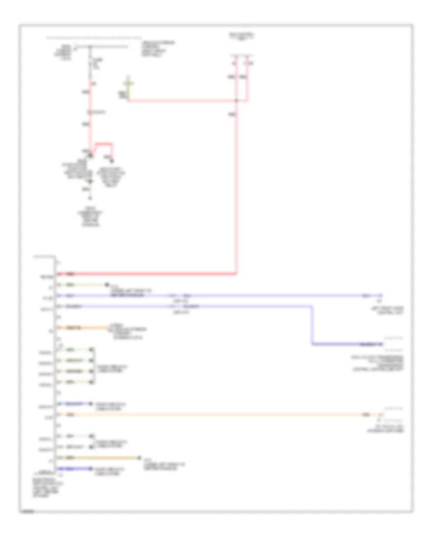
Power Distribution Wiring Diagram (5 of 5) for Mercedes-Benz CLA250 2014
List of elements for Power Distribution Wiring Diagram (5 of 5) for Mercedes-Benz CLA250 2014:
- A hf
- Aux (+)
- Can b h
- Can b l
- Can d h
- Can d l
- Can e h
- Can e l
- Can g h
- Can g l
- Computer data lines system
- Dual clutch transmission fully integrated transmission control controller unit
- Eco start/ stop function additional battery relay
- Eco start/stop function additional battery
- Electronic ignition switch control unit (left center of dash)
- Fm, am & cl (zv) antenna amplifier
- From k fuse 56 (diagram 1 of 5)
- From vehicle interior fuse box (diagram 2 of 5)
- Ft df
- Fuse 10a
- Left front door control unit
- Pb 30b
- Red
- Sam control unit
- Vehicle interior fuse box (right front footwell)
- W12 (under left front of center console)
- W83/2 (under right front of center console)
- X25/13-c1
- X35/1-c2
- X4/48-c1