ANTI-THEFT
Anti-theft & Central Locking Wiring Diagram (1 of 2) for Audi A4 Quattro 1997

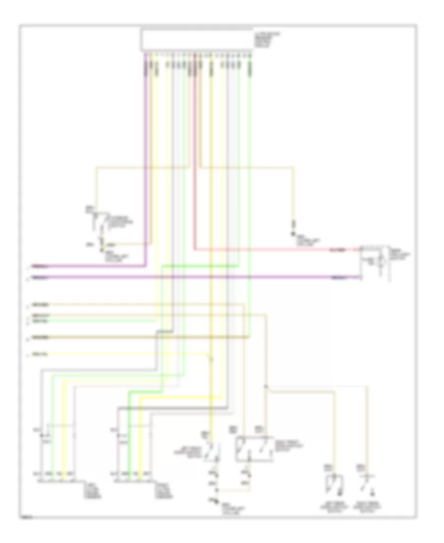
List of elements for Anti-theft & Central Locking Wiring Diagram (1 of 2) for Audi A4 Quattro 1997:
- (lower left
- (lower left "a" pillar)
- (not used)
- 14a
- 15/a
- 17/50a
- 19/50z
- 20/b
- 7/b
- 86s
- A-pillar)
- A/t
- Acc
- Alarm
- Alarm switch
- All times
- Antenna
- Battery
- Central electric panel
- Central locking/ alarm system/ interior light delay control module (right of luggage compt)
- Clutch pedal position switch
- Door lock switch
- Driver's door handle alarm switch
- Engine control module (ecm)
- Exterior lights system
- Function transmission range switch
- Fuse 10a
- Fuse 15a
- Fuse 5a
- Fuse panel
- G202 (behind left side of i/p)
- G404 (near left
- G900
- Hood
- Horn
- Hot at
- Hot in run
- Ignition switch
- Instrument cluster combination processor
- Interior lights system
- Interlock
- Key switch
- M/t (after 5/97)
- M/t (before 5/97)
- Multi-
- Nca
- Off
- Or acc
- Passenger's door handle alarm switch
- Power windows system
- Radio
- Red
- Relay
- S1/50z
- S4/50z
- S4/a
- S4/b
- S6/50a
- Start
- Starter
- Taillight)
- Trunk light switch
- Trunk lock alarm switch
Anti-theft & Central Locking Wiring Diagram (2 of 2) for Audi A4 Quattro 1997
List of elements for Anti-theft & Central Locking Wiring Diagram (2 of 2) for Audi A4 Quattro 1997:
- (lower left
- A-pillar)
- Alarm ind
- G900
- G900 (lower left a-pillar)
- Interior monitoring switch
- Left front door contact switch
- Left rear door contact switch
- Left ultra sound sensor
- Nca
- Rear fog loght switch
- Right front door contact switch
- Right rear door contact switch
- Right ultra sound sensor
- Ultra sound sensors control module