ENGINE PERFORMANCE
1.8L
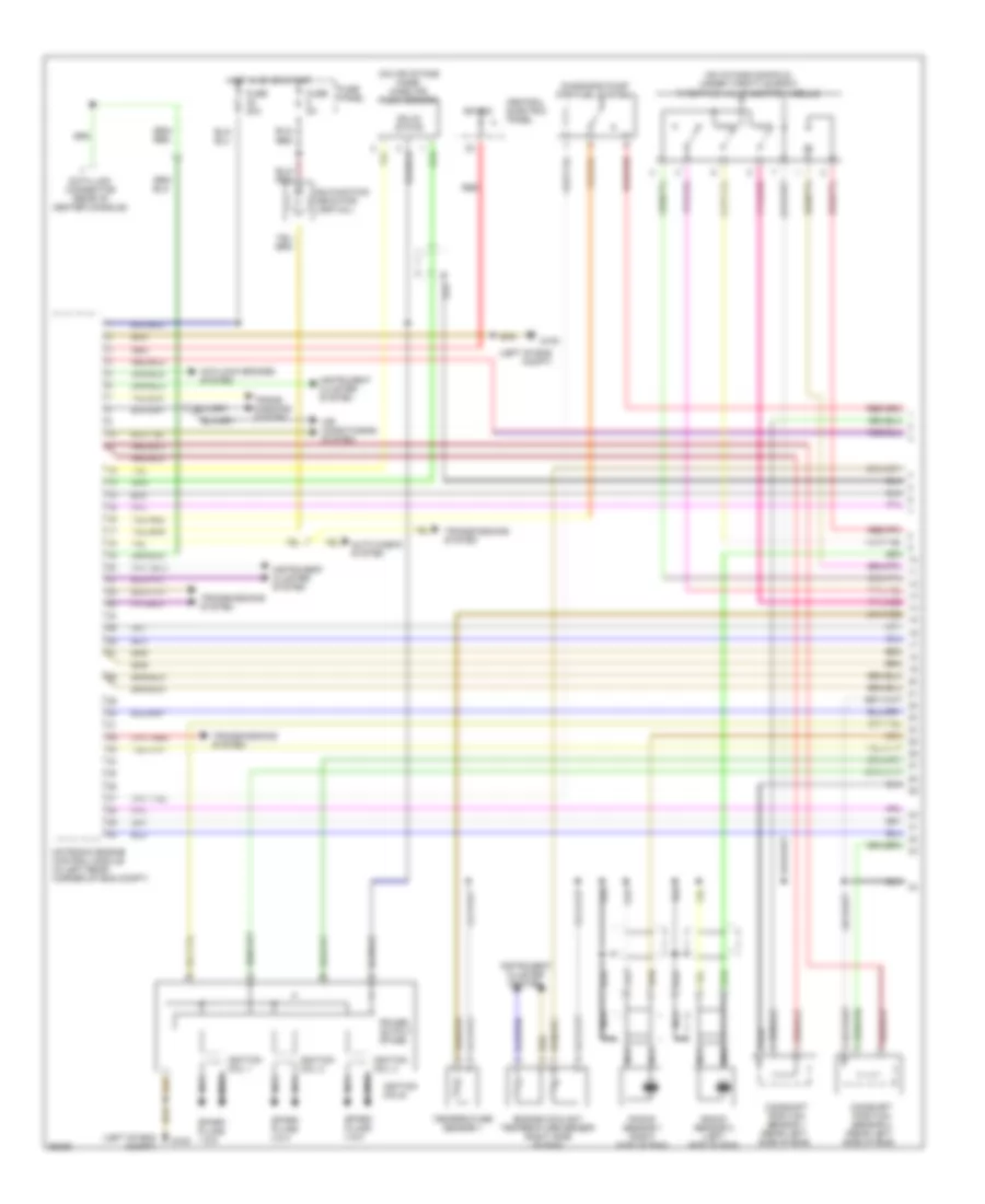
1.8L, Engine Performance Wiring Diagram (1 of 2) for Audi A4 Quattro 1997

List of elements for 1.8L, Engine Performance Wiring Diagram (1 of 2) for Audi A4 Quattro 1997:
- (left of eng compt)
- (on air intake hose) mass air flow sensor
- (on eng block)
- (on intake manifold, under throttle body) throttle valve control module
- Air conditioning system
- Bat(30)
- Camshaft position sensor (rear left side of eng)
- Central electric panel
- Data link connector (rear of center console)
- Diagnosis pump (for fuel system)
- Engine coolant temperature sensor (right side of eng)
- Fuse 10a
- Fuse 20a
- Fuse panel
- G100
- G132
- Hot in on or start
- Ignition coils
- Iii
- Instrument cluster system
- Intake air temperature sensor
- Knock sensor 1 (right side of eng)
- Knock sensor 2 (left side of eng)
- Malfunction indicator lamp (mil)
- Motronic engine control module (in left rear corner of eng compt)
- Nca
- Power output stage
- Red
- Spark plug
- T4f
- T5c
- Trans- missions system
- Transmissions system
- Transmissions system auto check system
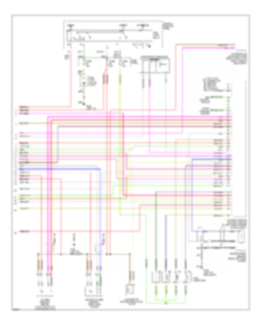
1.8L, Engine Performance Wiring Diagram (2 of 2) for Audi A4 Quattro 1997
List of elements for 1.8L, Engine Performance Wiring Diagram (2 of 2) for Audi A4 Quattro 1997:
- 87f
- 87f/dti
- 87a
- Abs control module
- Barometric pressure sensor
- Bat(30)
- Central electric panel
- Data link connector (rear of center console)
- Engine speed sensor (rear left side of eng)
- Evaporative canister purge regulator valve (right side of eng compt)
- Fuel injectors
- Fuel pump (in fuel tank)
- Fuel pump relay
- Fuse 10a
- Fuse 15a
- Fuse 20a
- Fuse panel
- G100 (left of eng compt)
- G202 (left i/p)
- Heated oxygen sensor 1 (right side of eng)
- Ign(15)
- Motronic engine control module (in left rear corner of eng compt)
- Nca
- Oxygen sensor 1 (behind 3 way catalytic converter (twc))
- Red
- Start(50a)
- Trans- missions system
- Wastegate bypass regulator valve
2.8L
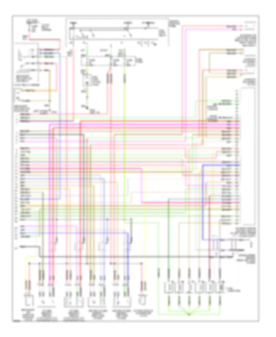
2.8L, Engine Performance Wiring Diagram (1 of 2) for Audi A4 Quattro 1997
List of elements for 2.8L, Engine Performance Wiring Diagram (1 of 2) for Audi A4 Quattro 1997:
- (left of eng compt)
- (on air intake hose) mass air flow sensor
- (on intake manifold, under throttle body) throttle valve control module
- Air conditioning system
- Antilock brakes system
- Auto check system
- Bat(30)
- Camshaft position sensor 1 (rear left side of eng)
- Camshaft position sensor 2 (rear left side of eng)
- Central electric panel
- Data link connector (rear of center console)
- Diagnosis pump (for fuel system)
- Engine coolant temperature sensor (right side of eng)
- Fuse 20a
- Fuse 5a
- Fuse panel
- G100
- Hot in on or start
- Ignition coil 1
- Ignition coil 2
- Ignition coil 3
- Ignition coils
- Instrument cluster system
- Knock sensor 1 (right side of eng)
- Knock sensor 2 (left side of eng)
- Malfunction indicator lamp (mil)
- Motronic engine control module (in left rear corner of eng compt)
- Nca
- Power output stage
- Red
- Solid state
- Spark plugs 1 & 6
- Spark plugs 2 & 4
- Spark plugs 3 & 5
- Temperature sensor ii
- Trans- missions system
- Transmissions system
2.8L, Engine Performance Wiring Diagram (2 of 2) for Audi A4 Quattro 1997
List of elements for 2.8L, Engine Performance Wiring Diagram (2 of 2) for Audi A4 Quattro 1997:
- (left of eng compt)
- 13-way relay carrier
- 3-way relay carrier
- 87f
- 87f/dti
- 87a
- Abs control module
- Bat(30)
- Camshaft adjusment valve 1
- Camshaft adjusment valve 2
- Central electric panel
- Engine speed sensor (rear left side of eng)
- Evaporative canister purge regulator valve (right side of eng compt)
- Fuel injectors
- Fuel pump (in fuel tank)
- Fuel pump relay
- Fuse 15a
- Fuse 20a
- Fuse 50a
- Fuse panel
- G100
- G202 (left i/p)
- Heated oxygen sensor 1 (right side of eng)
- Heated oxygen sensor 2 (left side of eng)
- Hot in on or start
- Ign(15)
- Intake manifold changeover valve
- Motronic engine control module (in left rear corner of eng compt)
- Nca
- Oxygen sensor 1 (behind 3 way catalytic converter (twc))
- Oxygen sensor 2 (behind 3 way catalytic converter (twc))
- Red
- Secondary air injection (air) relay
- Secondary air injection pump motor
- Secondary air injection solenoid valve
- Start(50a)
- Trans- missions system