AIR CONDITIONING
Automatic A/C Wiring Diagram (1 of 2) for Audi A4 Quattro 1997

List of elements for Automatic A/C Wiring Diagram (1 of 2) for Audi A4 Quattro 1997:
- A/c compressor speed sensor
- A/c control head
- Anti-theft system
- Back pressure flap motor and sensor
- Center outlet temperature sender
- Central flap motor and sensor
- Flap motor and sensor
- Floor outlet temperature sender
- Footwell/defroster
- Fresh air intake duct temperature sensor
- Fuse 10a
- Fuse panel
- G202 (left side of i/p)
- Hot at all times
- Instrument cluster
- Interior lights system
- Interior temperature fan & sensor
- Motronic engine control module
- Outside air temperature sensor
- Sunlight photo sensor
- T26
- T26a
- Temperature regulator flap motor and sensor
- Transmission control module
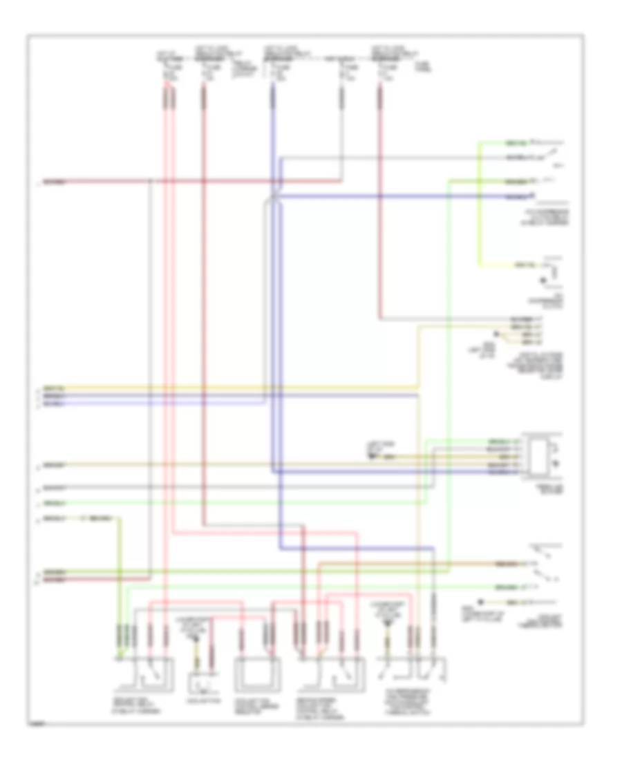
Automatic A/C Wiring Diagram (2 of 2) for Audi A4 Quattro 1997
List of elements for Automatic A/C Wiring Diagram (2 of 2) for Audi A4 Quattro 1997:
- (in relay carrier)
- (left side of i/p) g202
- (lower part of left "a" pillar) g202
- A/c compressor clutch
- A/c compressor clutch relay (in relay carrier)
- A/c refrigerant
- Coolant fan
- Coolant fan control relay
- Coolant fan control series resistor
- Coolant fan control thermal switch
- Digital outside air temperature/ transmission range selector lever display
- Fan control
- Fresh air blower
- Fuse 10a
- Fuse 30a
- Fuse 40a
- Fuse 5a
- Fuse panel
- G202 (left side of i/p)
- G202 (lower part of left "a" pillar)
- High pressure switch/coolant
- Hot at all times
- Hot in run
- Hot w/ load reduction relay energized
- Relay carrier (8-way)
- Second speed coolant fan control relay
- Thermal switch