ANTI-THEFT
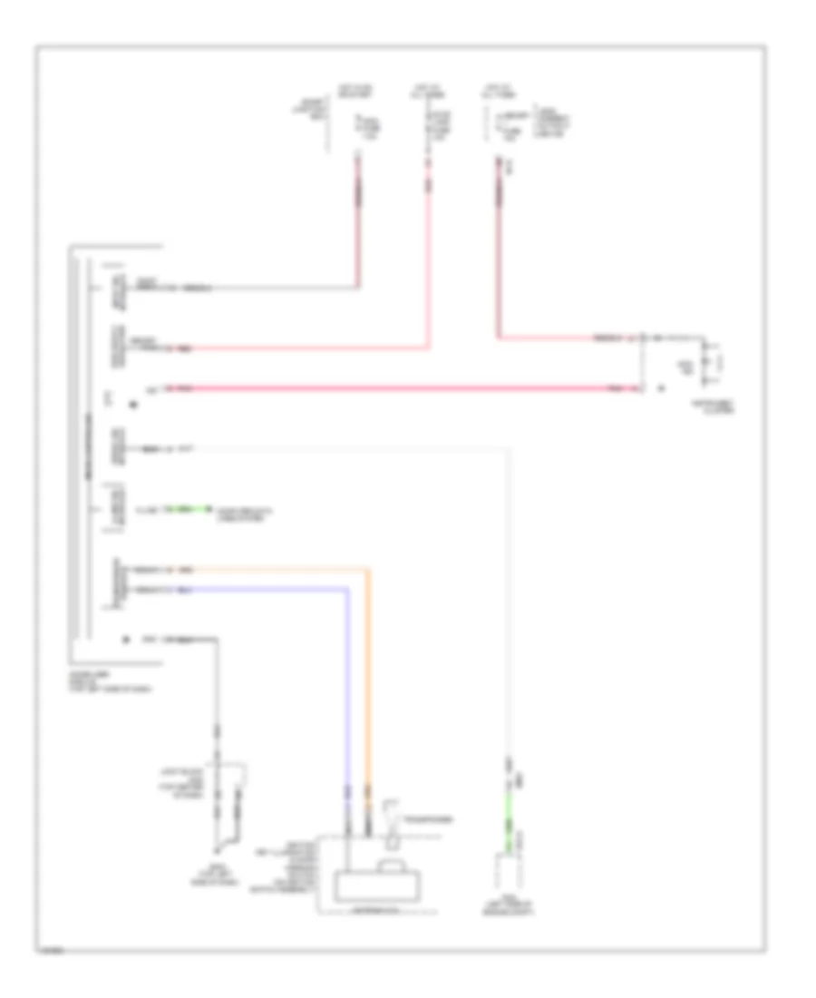
Forced Entry Wiring Diagram (1 of 3) for Hyundai Azera 2014

List of elements for Forced Entry Wiring Diagram (1 of 3) for Hyundai Azera 2014:
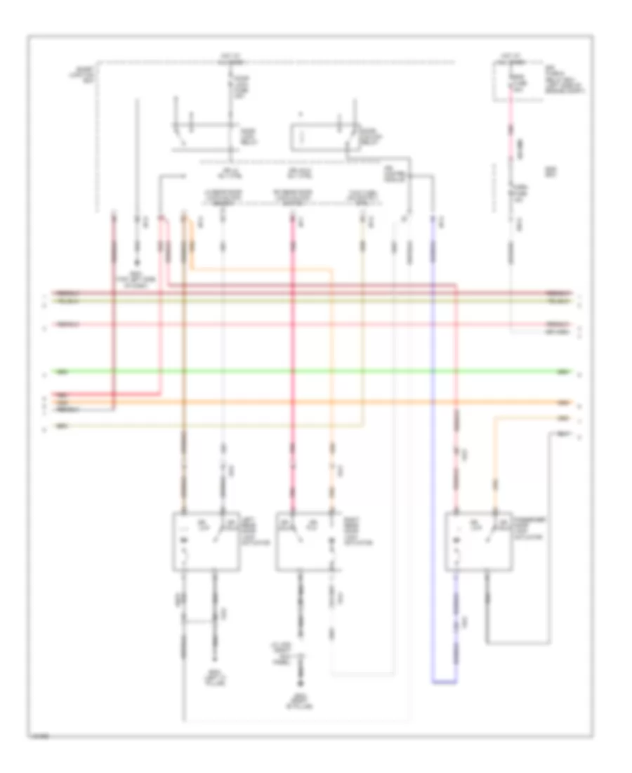
Forced Entry Wiring Diagram (2 of 3) for Hyundai Azera 2014
List of elements for Forced Entry Wiring Diagram (2 of 3) for Hyundai Azera 2014:
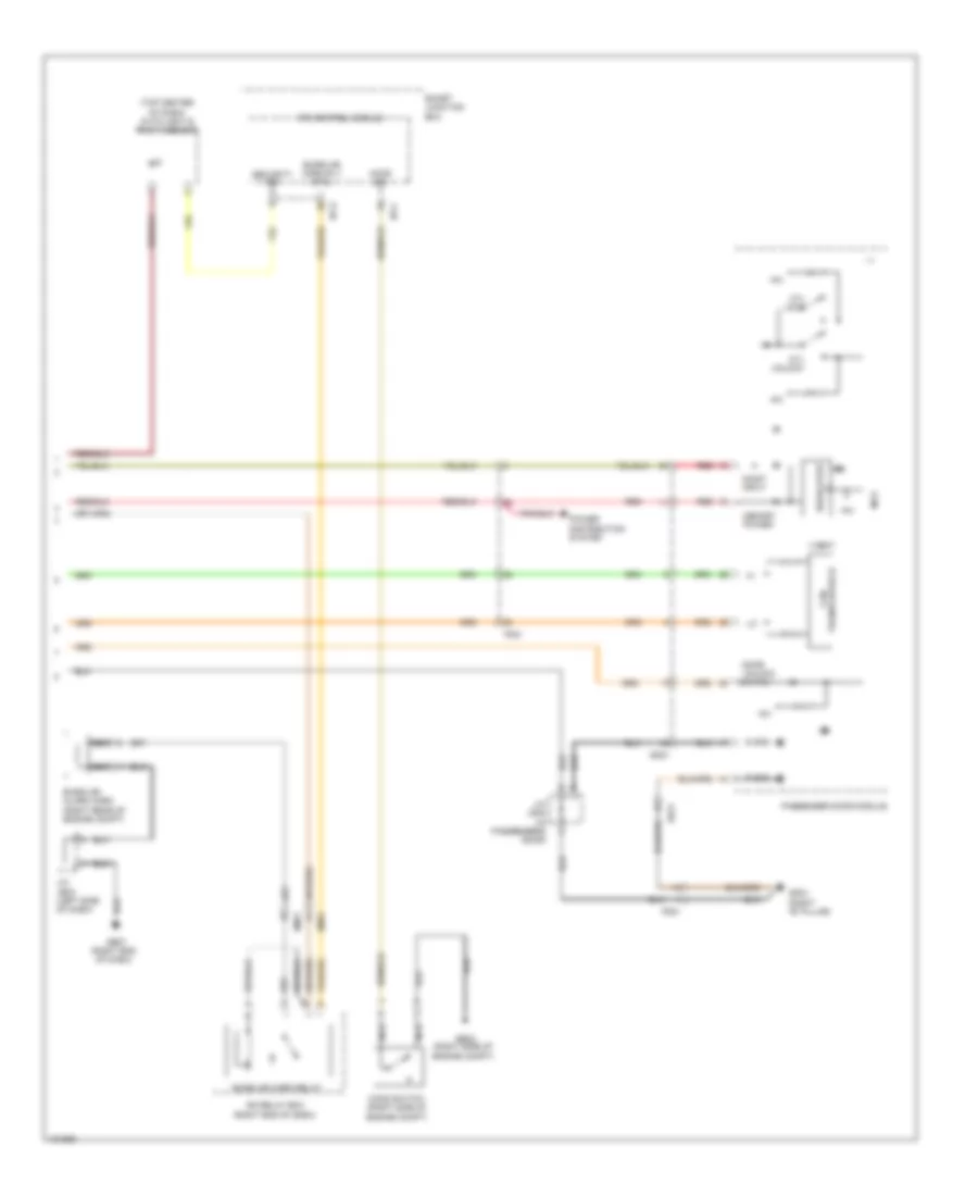
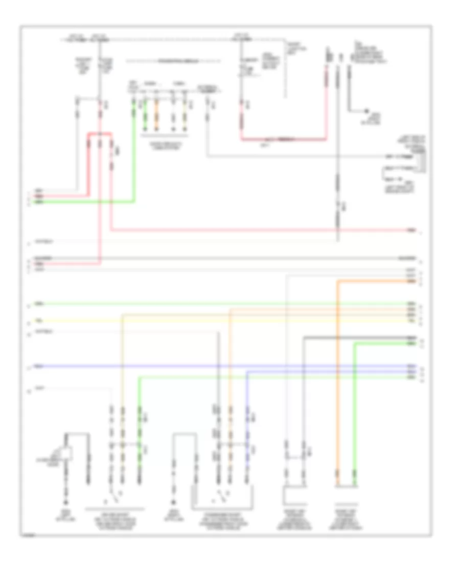
Forced Entry Wiring Diagram (3 of 3) for Hyundai Azera 2014
List of elements for Forced Entry Wiring Diagram (3 of 3) for Hyundai Azera 2014:
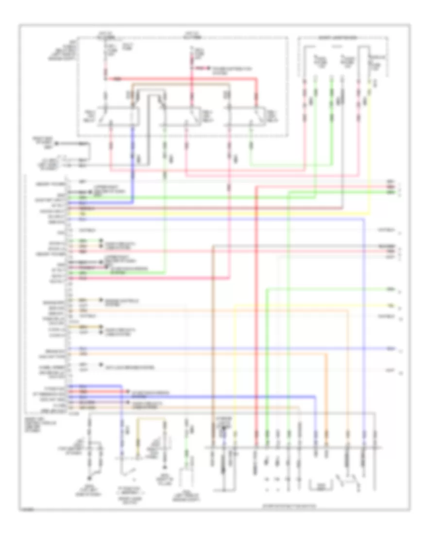
Immobilizer Wiring Diagram, with Smart Key System (1 of 3) for Hyundai Azera 2014
List of elements for Immobilizer Wiring Diagram, with Smart Key System (1 of 3) for Hyundai Azera 2014:
Immobilizer Wiring Diagram, with Smart Key System (2 of 3) for Hyundai Azera 2014
List of elements for Immobilizer Wiring Diagram, with Smart Key System (2 of 3) for Hyundai Azera 2014:
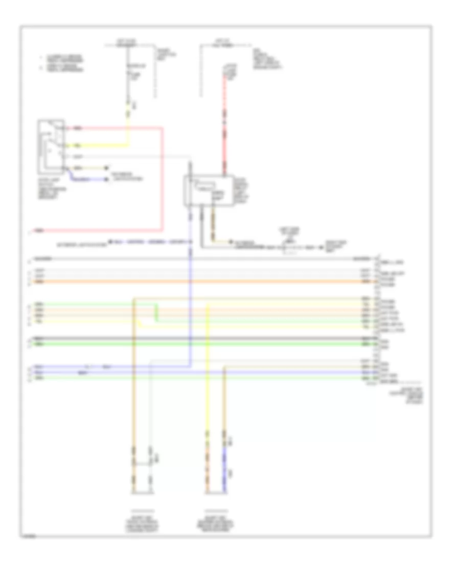
Immobilizer Wiring Diagram, with Smart Key System (3 of 3) for Hyundai Azera 2014
List of elements for Immobilizer Wiring Diagram, with Smart Key System (3 of 3) for Hyundai Azera 2014:
Immobilizer Wiring Diagram, without Smart Key System for Hyundai Azera 2014
List of elements for Immobilizer Wiring Diagram, without Smart Key System for Hyundai Azera 2014: