COMPUTER DATA LINES
Computer Data Lines Wiring Diagram (1 of 2) for Hyundai Azera 2014

List of elements for Computer Data Lines Wiring Diagram (1 of 2) for Hyundai Azera 2014:
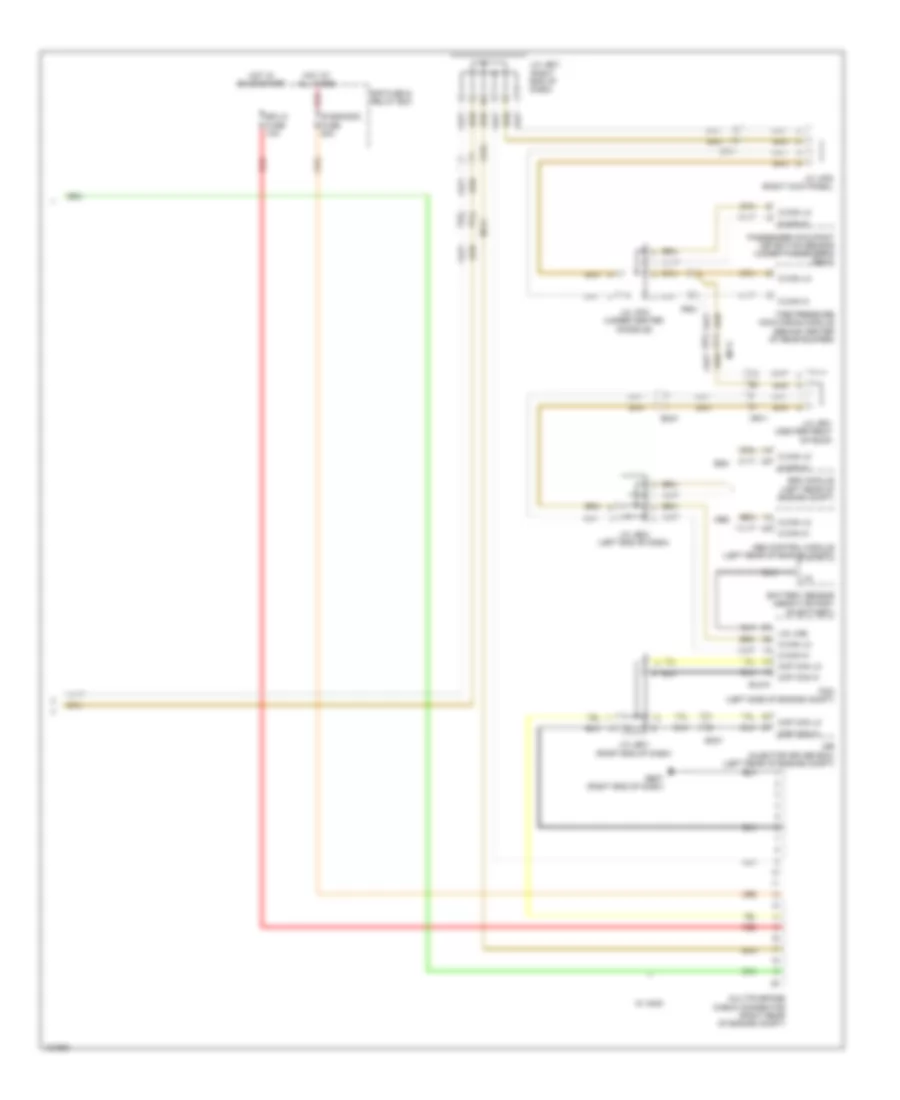
Computer Data Lines Wiring Diagram (2 of 2) for Hyundai Azera 2014
List of elements for Computer Data Lines Wiring Diagram (2 of 2) for Hyundai Azera 2014: