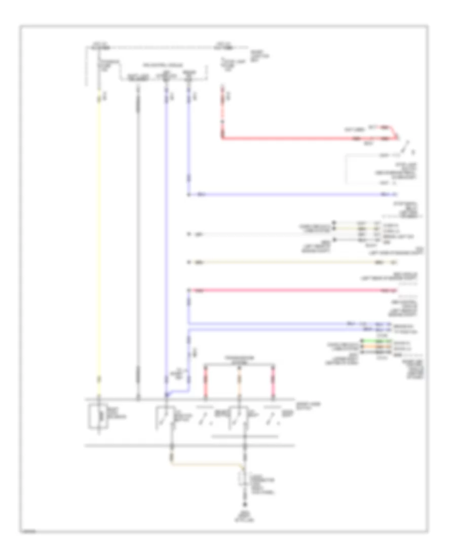
SHIFT INTERLOCK
Shift Interlock Wiring Diagram for Hyundai Azera 2014
List of elements for Shift Interlock Wiring Diagram for Hyundai Azera 2014:
- "p"
- "p" position
- (not used)
- Abs control module (left rear of engine compt)
- B-can hi
- B-can lo
- Brake light sw
- Brake sw
- Brake sw (n.o)
- C-can hi
- C-can lo
- Computer data lines system
- Down shift
- Elg-a
- Em31
- Esc module (left rear of engine compt)
- Ge05 (left rear of engine compt)
- Gf03 (right "b" pillar)
- Gm07 (upper right center of dash)
- Gnd
- Hot at all times
- I/p-a
- I/p-c
- I/p-d
- I/p-f
- Ips control module
- Joint connector jf05 (right kick panel)
- Key
- Key interlock sw
- M13-a
- M13-b
- Mf21
- P/handle fuse 15a
- Pcm (left side of engine compt)
- Pnk
- Position switch
- Red
- Select switch
- Shift lock solenoid
- Smart
- Smart junction box
- Smart key control module (center of dash)
- Sport mode switch
- Stop lamp fuse 10a
- Stop lamp switch (above brake pedal, on bracket)
- Stop signal relay (left end of dash)
- Transmissions system
- Up shift
 English