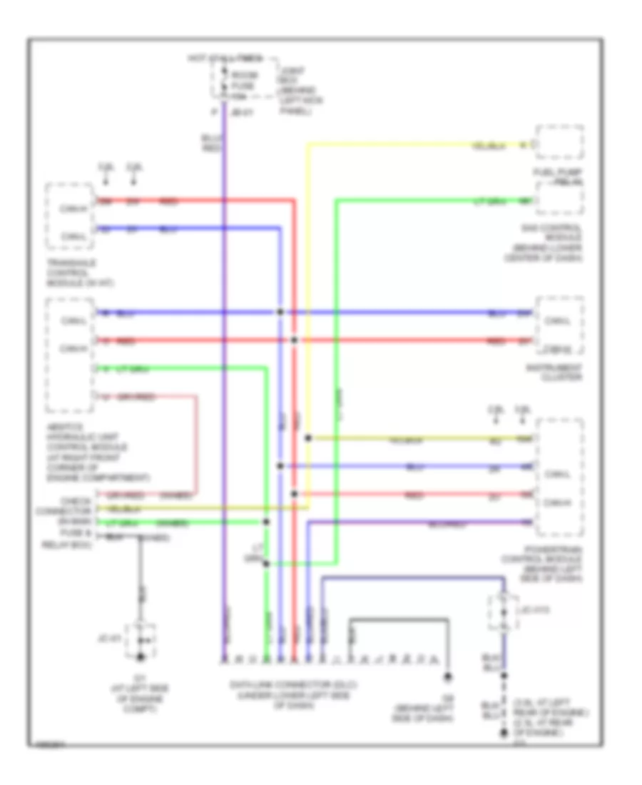
AUTOMOTIVE ELECTRICIANS PORTAL

COMPUTER DATA LINES – Mazda 6 i 2004 – SYSTEM WIRING DIAGRAMS

COMPUTER DATA LINES

Computer Data Lines Wiring Diagram for Mazda 6 i 2004

Computer Data Lines Wiring Diagram for Mazda 6 i 2004 https://portal-diagnostov.com/license.html
https://portal-diagnostov.com/license.html Automotive Electricians Portal FZCO Automotive Electricians Portal FZCO
Get access to all wiring diagrams of the carDownload PDF file

List of elements for Computer Data Lines Wiring Diagram for Mazda 6 i 2004:

  • (3.0l: at left rear of engine) (2.3l: at rear of engine) g3
  • (w/abs)
  • 2.3l
  • 3.0l
  • Abs/tcs hydraulic unit control module (at right front corner of engine compartment)
  • Can-h
  • Can-l
  • Check connector (in main fuse &
  • Data link connector (dlc) (under lower left side of dash)
  • Fuel pump relay
  • G1 (at left side of engine compt)
  • G8 (behind left side of dash)
  • Hot at all times
  • Instrument cluster
  • Jb-01
  • Jc-01
  • Jc-x13
  • Joint box (behind left kick panel)
  • Powertrain control module (behind left side of dash)
  • Red
  • Relay box)
  • Room fuse 15a
  • Sas control module (behind lower center of dash)
  • Transaxle control module (w /at)